1
UM10732
NXP Semiconductors
Chapter 9: LPC11U6x/E6x Pin interrupt and pattern match engine
6<6&21
3,2B>@
3,2B>@
3,2B>@
L
('*(/(9(/
'(7(&7/2*,&
19,&SLQLQWHUUXSW
('*(/(9(/
'(7(&7/2*,&
19,&SLQLQWHUUXSW
3,176(/
3,2B>@
3,2B>@
3,2B>@
L
3,176(/
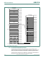
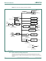
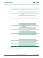
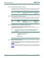
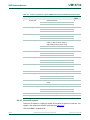
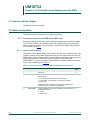
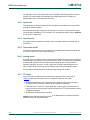
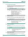
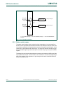
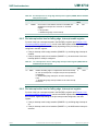
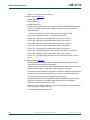
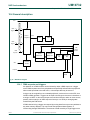
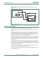
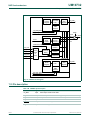
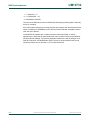
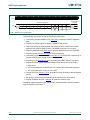
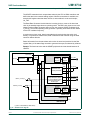
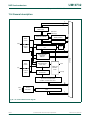
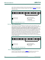
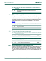
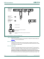
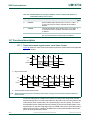
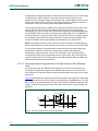
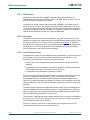
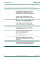
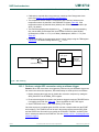
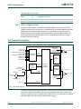
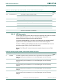
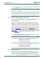
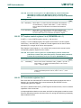
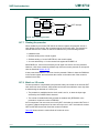
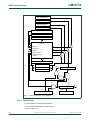
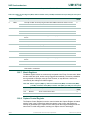
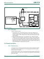
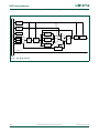
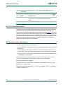
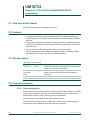
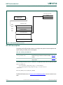
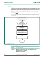
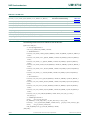
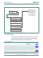
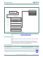
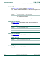
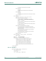
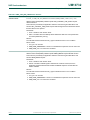
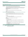
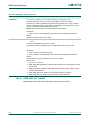
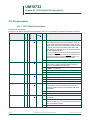
n = 6 for the DIP8 package, n= 14 for the TSSOP16 package, n = 18 for the TSSOP/SOP20
packages.
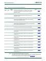
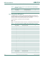
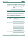
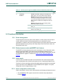
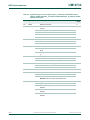
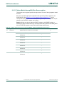
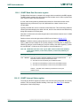
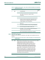
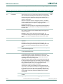
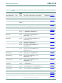
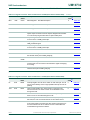
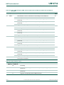
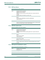
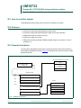
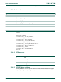
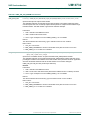
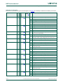
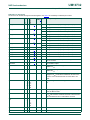
Fig 10. Pin interrupt connections
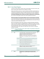
9.5.2 Pattern match engine
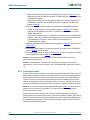
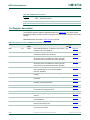
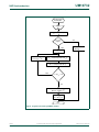
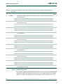
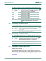
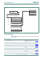
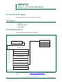
The pattern match feature allows complex boolean expressions to be constructed from
the same set of eight GPIO pins that were selected for the GPIO pin interrupts. Each term
in the boolean expression is implemented as one slice of the pattern match engine. A slice
consists of an input selector and a detect logic. The slice input selector selects one input
from the available eight inputs with each input connected to a pin by the input’s PINTSEL
register.
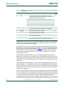
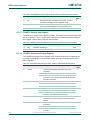
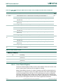
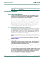
The detect logic monitors the selected input continuously and creates a HIGH output if the
input qualifies as detected. Several terms can be combined to a minterm by designating a
slice as an endpoint of the expression. A pin interrupt for this slice is asserted when the
minterm evaluates as true.
UM10732
User manual
All information provided in this document is subject to legal disclaimers.
Rev. 1.4 — 28 October 2015
© NXP B.V. 2015. All rights reserved.
114 of 610