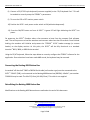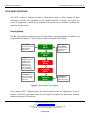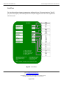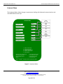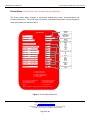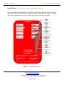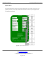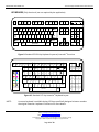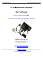
1
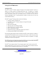
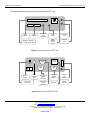
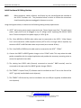
PERIPHERAL EXCHANGE LLC Technical Support Release & Document Archives ISCPC Intecolor Emulator User’s Manual Manual P/N PE999373-ISCPC-010-BP01 Custom configuration for the W. H. Zimmer Generating Station, Moscow, Ohio (A Duke Energy Company) PERIPHERAL EXCHANGE LLC P.O. Box 2831, Cashiers, NC 28717-2831 United States of America E-mail: [email protected] Web: www.peripheralexchange.com P.O. Box 2831, Cashiers, NC 28717-2831 U.S.A. Email: [email protected] Web: http://www.peripheralexchange.com All trademarks and registrations acknowledged. Content subject to change. Copyright © 2015 Peripheral Exchange LLC. All rights reserved. Page 1 of 19 PERIPHERAL EXCHANGE LLC Technical Support Release & Document Archives The contents of this document may not be reproduced in any form by any means without the prior written consent of Peripheral Engineering. Direct inquiries to: PERIPHERAL EXCHANGE LLC P.O. Box 2831, Cashiers, NC 28717-2831 United States of America SPOC Mr. G.A. Boughey Email: [email protected] Web: www.peripheralexchange.com Peripheral Exchange (PE) assumes no liability for loss or damage resulting from the uses or misuse of information contained within this document or from errors or omissions, which it might contain. PE reserves the right to modify or revise the content of this document without obligation to notify any person of such revisions or changes. No warranty of any kind is made or implied with regard to the software described in this document or its merchantability or fitness for a particular purpose. This software is furnished under license agreement and may be used only in accordance within the terms of the agreement. This document, submitted in confidence, contains proprietary information, which shall not be reproduced or transferred to other documents, disclosed to others, or used for manufacturing or for any other purpose without prior written permission from PE. Intecolor is a registered trademark of Rockwell Automation. ITE8001 is a custom software release provided by Mirador Software for exclusive distribution by Peripheral Exchange. ISCPC and ITE8001 are registered trademarks of Peripheral Exchange. ITE8001 can be located at http://www.peripheralexchange.com/ITE8001/ITE8001.htm P.O. Box 2831, Cashiers, NC 28717-2831 U.S.A. Email: [email protected] Web: http://www.peripheralexchange.com All trademarks and registrations acknowledged. Content subject to change. Copyright © 2015 Peripheral Exchange LLC. All rights reserved. Page 2 of 19 PERIPHERAL EXCHANGE LLC Technical Support Release & Document Archives P.O. Box 2831, Cashiers, NC 28717-2831 U.S.A. Email: [email protected] Web: http://www.peripheralexchange.com All trademarks and registrations acknowledged. Content subject to change. Copyright © 2015 Peripheral Exchange LLC. All rights reserved. Page 3 of 19 PERIPHERAL EXCHANGE LLC Technical Support Release & Document Archives Setting Up the ISCPC Emulator Installing the ISCPC The ISCPC Intecolor Emulator supports all features of the original Intecolor terminal. In addition, this release supports the Betalog 4000 button box. A hardware kit is supplied containing four (4) screws to hard mount the unit to a VESA compliant 100mm mounting pattern. Alternatively, rubber feet are provided to place on a desktop. Since the product is extremely lightweight, Velcro mounting would be suitable to mount the unit to any flat surface deemed necessary. The ISCPC Intecolor Emulator product contains the following: The ISCPC Intecolor Emulator unit The ITE8001 Intecolor Emulator software on Compact Flash media USB licensing key Wall mount power supply VGA video cable 1-foot HD15M to HD15M COM1 RS-232C cable 1-foot DB9F to DB25M DB25F to DB25F gender changer Hardware kit (4-screws, 4-rubber feet, ample strips of Velcro) ISPC Manual (P/N PE999373-ISCPC-010-BP01) The wall-mount power supply must be connected to the ISCPC power input port. In addition, a standard PC/AT PS/2 keyboard must be connected to the PS/2 port to select the various setup selections. Once the settings are correctly selected and saved, the keyboard is no longer needed unless required by the application. The USB license key must always be connected to the USB port on the rear side of the ISCPC unit as indicated below, otherwise the product will not function. The ISCPC has two power switches. The main power supply “rocker” switch must be set ON (white dot depressed) on the rear of the unit. A “soft start” power switch is located on the front of the unit. This is a pushbutton switch that acts as a “reset switch”. P.O. Box 2831, Cashiers, NC 28717-2831 U.S.A. Email: [email protected] Web: http://www.peripheralexchange.com All trademarks and registrations acknowledged. Content subject to change. Copyright © 2015 Peripheral Exchange LLC. All rights reserved. Page 4 of 19 PERIPHERAL EXCHANGE LLC Technical Support Release & Document Archives Pictured below are the front and rear views of the ISCPC unit. Compact Fash Card USB Spare USB Port USB Spare USB Port Audio Input (Not Supported) ISC8XXXSoftware Compact Flash Card Audio Output CF Activity LED Pow er ON/OFF Reset Sw itch Pow er ON LED Figure 1: Front View of the ISPC unit VGA COM 1 PS/2 Keyboard Port Main AC ON/OFF Pow er Supply Input Port COM1 9-pin RS232 Serial Port VGA 15-pin Video Output Port 10/100 T-base U S B COM 2 COM2 9-pin RS232 Serial Port WLAN (Not Supported) Ethernet Spare USB Port Figure 2: Rear View of the ISPC unit P.O. Box 2831, Cashiers, NC 28717-2831 U.S.A. Email: [email protected] Web: http://www.peripheralexchange.com All trademarks and registrations acknowledged. Content subject to change. Copyright © 2015 Peripheral Exchange LLC. All rights reserved. Page 5 of 19 PERIPHERAL EXCHANGE LLC Technical Support Release & Document Archives Initial Hardware & Cabling Hookup NOTE: Before shipment, cables, software, and license key are preconfigured and attached to the ISCPC Emulator unit. The procedure below is meant to outline the connections should something become unplugged in shipment or on site. Using the diagrams above, to determine the following cabling hookup requirements: 1) ISCPC wall-mount power supply connected to the “Power Supply Input Port”. The wall-mount power supply itself must be plugged in any AC voltage source supplying 100-240VAC 50/60 Hertz. The actual output of the power supply is +5VDC @ 3A. 2) The 1-foot HD15M to HD15M video cable must be connected on the ISCPC “Video Output Port” and connected to a VGA compliant monitor (CRT or LCD). If a longer cable is required, any extension HD15F to HD15M video cable may be used (not to exceed 16 feet). 3) The 1-foot DB9F to DB25M serial cable must be connected to the ISCPC “COM1”. 4) Connect the DB25F to DB25F gender changer to the “COM1” cable. This step makes the cable gender compatible with the original application and provides the necessary mounting points to secure the application host cable. 5) The existing host RS232 cable (formerly connected to Intecolor 8865 terminal) must be connected to the open end of the DB25F gender changer (COM1). 6) The ITE8001 Compact Flash (CF) software must be installed into the CF slot on the front of the ISCPC (typically installed before unit shipment). 7) The ITE8001 USB license key must be installed on the rear USB port (typically installed before unit shipment). P.O. Box 2831, Cashiers, NC 28717-2831 U.S.A. Email: [email protected] Web: http://www.peripheralexchange.com All trademarks and registrations acknowledged. Content subject to change. Copyright © 2015 Peripheral Exchange LLC. All rights reserved. Page 6 of 19 PERIPHERAL EXCHANGE LLC Technical Support Release & Document Archives 8) Connect a PC/AT PS2-style keyboard (customer supplied) to the “PS/2 Keyboard Port”. This will be needed to correctly setup the ITE8001’s parameters. 9) Turn on the LCD or CRT monitor power switch. 10) Position the ISCPC main power rocker switch to ON (white dot depressed). 11) Press the ON/OFF button on front of ISCPC. A green LED will light indicating the ISCPC has power. On power-up, the ISCPC Emulator takes a few moments to boot from the compact flash software card. The entire process to load the emulator environment takes less than 30 seconds. Once finished loading, the emulator will initialize and present the “ITE8001 V2.20” header message (or custom header) on the display monitor. At this point, the ISCPC will be fully functional as a standard Intecolor 8001, 3800, or 8800 Series terminal. Using the PC/AT keyboard, follow the steps below to correctly configure the ITE8001 software for the application. Once selections have been made AND stored, the keyboard may be removed. Connecting the Betalog 4000 Button Box A standard “off-the-shelf” DB9F to DB25M Serial cable (null modem type) must be connected to the ISCPC “COM2” (DB9), and connected to the Betalog 4000 button box (DB25M). A Belkin part number F2L088-XX may be used. The XX=03 (3-foot), XX=06 (6-foot). This cable is not supplied. Retrofitting the Betalog 4000 Button Box Modifications to the Betalog 4000 button box are outlined at the end of this document. P.O. Box 2831, Cashiers, NC 28717-2831 U.S.A. Email: [email protected] Web: http://www.peripheralexchange.com All trademarks and registrations acknowledged. Content subject to change. Copyright © 2015 Peripheral Exchange LLC. All rights reserved. Page 7 of 19 PERIPHERAL EXCHANGE LLC Technical Support Release & Document Archives SETUP MENU OPERATION The ISCPC Intecolor Emulator provides a Setup Menu system to allow changes to most parameters normally not changeable on the standard Intecolor terminal. The menus are similar in appearance to those of the standard terminal and may be accessed, modified, and saved in a similar manner. Entering Setup The Alt + Esc keyboard sequence enters the Setup Menu. (Simply hold down the Alt key and press the Esc key together). The first menu to appear will be the HOST MENU. ALT + ESC keyboard sequence enters the Menu system here HOST MENU Use of ALT with UP or DOWN arrow keys select the next menu in sequence KEYBOARD MENU The Printer & Locator menus are available, but not required by the application. Any settings provided due not effect the primary application. The use of the UP and DOWN arrow keys allow changes to selections within each menu PRINTER MENU LOCATOR MENU OPTIONS MENU The ENTER key exits from any menu at any time Figure 3. Menu System Flow Diagram In this special ISCPC implementation, the typical default values are highlighted in bold. In addition, the Printer and Locator Menu are not required to support the application, although these functions are fully functional. P.O. Box 2831, Cashiers, NC 28717-2831 U.S.A. Email: [email protected] Web: http://www.peripheralexchange.com All trademarks and registrations acknowledged. Content subject to change. Copyright © 2015 Peripheral Exchange LLC. All rights reserved. Page 8 of 19 PERIPHERAL EXCHANGE LLC Technical Support Release & Document Archives Host Menu The Host Menu allows changes to parameters dealing with host I/O communications. The I/O port, data rate, duplex, and related parameters may be changed to meet the user’s application and then saved. Serial HOST MENU Local Host Interface Serial Local/Line Line Duplex Full Line Full Half Echo COM1 COM2 Serial Port COM1 Flow Control ^S^Q Data Rate 9600 Bits per Char 8 Parity None Stop Bits 1 TX Pacing Off 9600 12.5% 12900 38400 Pacing Duty None ^S^Q ^F^G RTS/CTS 75 150 300 600 1200 2400 4800 7 8 None Odd Even 1 2 1 2 3 4 5 To Save Current Setup. To Recall saved setup. To Recall FACTORY setup. To Recall ‘ 8001G’ setup. To Exit Emulator. Cmd or Alt + Dn or Up Arrow Key Up and Down Arrow Keys Left and RightArrow Keys ENTER Off On 6.25% 12.5% 25% 50% To move from menu to menu To move from item to item To change item’s setting To exit setup mode ISCPC & ITE8001 Copyright (c) 2015 by Peripheral Exchange Figure 4. Host Menu P.O. Box 2831, Cashiers, NC 28717-2831 U.S.A. Email: [email protected] Web: http://www.peripheralexchange.com All trademarks and registrations acknowledged. Content subject to change. Copyright © 2015 Peripheral Exchange LLC. All rights reserved. Page 9 of 19 PERIPHERAL EXCHANGE LLC Technical Support Release & Document Archives Keyboard Menu The Keyboard Menu allows changes to parameters dealing with keyboard communications and user-definable function keys. 8810 KEYBOARD MENU 8810 SAB2 8810 Keyboard Type COM1 COM2 COM2 Serial Keyboard Port Off On Off Keyclick Off On Slow On Auto-repeat Fast Default Function Key Rate Fast Function Key Mode Default User Definitions Off Off Program Function Key 1 2 3 4 5 On To Save Current Setup. To Recall saved setup. To Recall FACTORY setup. To Recall ‘ 8001G’ setup. To Exit Emulator. Cmd or Alt + Dn or Up Arrow Key Up and Down Arrow Keys Left and RightArrow Keys ENTER To move from menu to menu To move from item to item To change item’s setting To exit setup mode ISCPC & ITE8001 Copyright (c) 2015 by Peripheral Exchange Figure 5. Keyboard Menu P.O. Box 2831, Cashiers, NC 28717-2831 U.S.A. Email: [email protected] Web: http://www.peripheralexchange.com All trademarks and registrations acknowledged. Content subject to change. Copyright © 2015 Peripheral Exchange LLC. All rights reserved. Page 10 of 19 PERIPHERAL EXCHANGE LLC Technical Support Release & Document Archives Printer Menu (Fully functional, but not required by the application) The Printer Menu allows changes to parameters dealing with printer communications and printout preferences. The printer type, orientation, and related parameters may be changed to meet user preference and then saved. Disabled PRINTER MENU Enabled Printer Disabled Printer Type HP/PCL3 Color Orientation Portrait BG Color (mono mode) Black Blk/White reverse (color mode) On Map black (color mode) Black Map red (color mode) Red Map green (color mode) Green Map yellow (color mode) Yellow Map blue (color mode) Blue BMP (file) HP/PCL3 Color HP/PCL3 Mono Portrait Landscape Black Map magenta (color mode) Magenta Map cyan (color mode) Cyan Map white (color mode) White Printer Port Red Green Yellow Blue Magenta Cyan White Off On Black Red Green Yellow Blue Magenta Cyan White USB USB 1 2 3 4 5 To Save Current Setup. To Recall saved setup. To Recall FACTORY setup. To Recall ‘ 8001G’ setup. To Exit Emulator. Cmd or Alt + Dn or Up Arrow Key Up and Down Arrow Keys Left and RightArrow Keys ENTER To move from menu to menu To move from item to item To change item’s setting To exit setup mode ISCPC & ITE8001 Copyright (c) 2015 by Peripheral Exchange Figure 6. Printer Menu Selections P.O. Box 2831, Cashiers, NC 28717-2831 U.S.A. Email: [email protected] Web: http://www.peripheralexchange.com All trademarks and registrations acknowledged. Content subject to change. Copyright © 2015 Peripheral Exchange LLC. All rights reserved. Page 11 of 19 PERIPHERAL EXCHANGE LLC Technical Support Release & Document Archives Locator Menu (Fully functional, but not required by the application) The Locator Menu allows changes to parameters dealing with input device selection, I/O port selection, and host report parameters. The device type, I/O port, data rate, duplex, reporting mode, and related parameters may be changed to meet user preference and saved. Disabled Enabled Disabled on Pick LOCATOR MENU None Arrow Keys Locator Disabled Device Type PS/2 Mouse Locator Curs or Type Box Curs or Mode Locator Only Audio Off Report/Pick Mode Tracking/Exit Pick Report Format 8001G Style Locator Port COM2 Sensitivity Medium Calibrate Off PS/2 Mouse Carroll Touch LX200 Trackball Serial Mouse None Under/Overscore Box Block Underscore Locator Only Host and Locator Host Only Off On No Pick Tracking/Exit Pick Tracking/Movement Pick Entry Pick Tracking/Continuous Pick None Pick Only 8001G Style 8001G Style Short ANSI Style ANSI Style Short VT100 Style COM1 COM2 1 2 3 4 5 To Save Current Setup. To Recall saved setup. To Recall FACTORY setup. To Recall ‘ 8001G’ setup. To Exit Emulator. Very Low Low Medium High Off On Cmd or Alt + Dn or Up Arrow Key menu Up and Down Arrow Keys Left and RightArrow Keys ENTER To move from menu to To move from item to item To change item’s setting To exit setup mode ISCPC & ITE8001 Copyright (c) 2015 by Peripheral Exchange Figure 7. Locator Menu Selections P.O. Box 2831, Cashiers, NC 28717-2831 U.S.A. Email: [email protected] Web: http://www.peripheralexchange.com All trademarks and registrations acknowledged. Content subject to change. Copyright © 2015 Peripheral Exchange LLC. All rights reserved. Page 12 of 19 PERIPHERAL EXCHANGE LLC Technical Support Release & Document Archives Options Menu The Options Menu allows changes to parameters dealing with cursor mode, character set, pixel graphics, Fastscreen, cursor style, and CRT saver functions. The items may be changed to meet user preference and saved. Off On OPTIONS MENU Line Monitor Off Host Curs or Mode Host Curs or Type Character Set Scroll Under/Overscore Lowercase Backspace Code ANSI Commands Protect Commands Fastscreen Commands Fastcreen Reports Graphics Commands Graphic Color Mapping Hold Screen ^S^Q ^H Enabled Disabled Disabled Disabled Enabled Enabled Off Terminal Bell Select Sound Sound Volume Standard subalert 12 Page Write 45Dn Write 45Up Wr Back Scroll Write Vert None Under/Overscore Box Block Underscore Process Forms Custom 1 Custom 2 Custom 3 Custom 4 Lowercase ^Z ^H Disabled CRT Screen Saver Allow CMD-X Exit Off Enabled No Off On Data Capture Off Disabled Standard Use Sound 1 2 3 4 5 To Save Current Setup. To Recall saved setup. To Recall FACTORY setup. To Recall ‘ 8001G’ setup. To Exit Emulator. Cmd or Alt + Dn or Up Arrow Key Up and Down Arrow Keys Left and RightArrow Keys ENTER To move from menu to menu To move from item to item To change item’s setting To exit setup mode ISCPC & ITE8001 Copyright (c) 2015 by Peripheral Exchange subalert tada chord ding chimes drbell siren wail hilo wawa 0 thru15 Off 1 Min 5 Min 10 Min 20 Min No Yes Off On Figure 8. Options Menu Selections P.O. Box 2831, Cashiers, NC 28717-2831 U.S.A. Email: [email protected] Web: http://www.peripheralexchange.com All trademarks and registrations acknowledged. Content subject to change. Copyright © 2015 Peripheral Exchange LLC. All rights reserved. Page 13 of 19 PERIPHERAL EXCHANGE LLC Technical Support Release & Document Archives KEYBOARDS (Fully functional, but not required by the application) F1 Esc Sh F0 ~ ` ! 1 Tab F2 F3 @ 2 Q Cap sLock F4 Sh F13 Sh F14 # 3 W A Ctrl % 5 E S Z Shift $ 4 ^ 6 R D X F6 F5 Sh F15 & 7 T F Y G C V Alt F7 * 8 U H B F8 ( 9 I ) 0 O J N F9 F10 F11 F12 K + = { [ P Backspace " ' Space Bar Insert Home Erase Char Page Num Lock _. . Erase Line 7 8 Home Enter Up ? / > . Num Lock Delete Char } ] : ; L < , M _ - Shift Alt Caps Lock Print Scroll Pause Screen Lock 4 5 1 2 Left Down Right X _ 9 Erase Page + 6 3 Erase Line Enter . 0 Ctrl Scroll Lock Delete Char Insert Char Figure 9. Standard PC 101-Key Keyboard Layout w/ Intecolor Functions F0 F1 F2 F3 F4 F5 F6 F7 F8 AUTO FG ON BG ON BLINK 2X/BL ON OFF ! " 1 2 ESC Blk Blu Red Mag Grn Cyn Yel Wht TAB CONTROL SHIFT COMMAND Q 3 W A Z ALPHA LOCK { | [ F11 F12 } ~ ] ^ % & ' ( ) 4 5 6 7 8 9 R D X 2X CHAR ON F10 $ E S F9 T F C Y G V U H B J N M F13 F14 F15 DEL = 0 I O K L + * ; : < > ? , . / SPACE BAR BREAK P ` @ SETUP INSERT DELETEDELETE INSERT CHAR CHAR LINE LINE HOME _ ERASE ERASE PAGE LINE R E T U R N SHIFT REPT 7 8 9 . . 4 5 6 X 1 2 3 - 0 . = + Figure 10. Standard 117-Key Intecolor Keyboard Layout NOTE: A custom keyboard is available having 122-keys specifically designed to better emulate the original Intecolor keyboard. Contact us for more details. P.O. Box 2831, Cashiers, NC 28717-2831 U.S.A. Email: [email protected] Web: http://www.peripheralexchange.com All trademarks and registrations acknowledged. Content subject to change. Copyright © 2015 Peripheral Exchange LLC. All rights reserved. Page 14 of 19 PERIPHERAL EXCHANGE LLC Technical Support Release & Document Archives Betalog 4000 Button Box Details The original Betalog 4000 button box MUST be modified to function properly with the ISCPC Emulator. The modifications are slight and relatively easy to perform. Several photos below help locate the areas needing attention. Set Jumper to G&H For TTL Data To Rear Panel GND Post Jumper Must be A&B For 1200 Baud (Default) To Rear Panel +5VDC Post Figure 11. Inside view of Betalog 4000 button box PCB Two wires must be added to allow an external +5DC power supply connection to the PCB. It is suggested that a pair of 20AWG-insulated wire, 1-Red & 1-Black (approx 8” long) be installed as shown. These lead to the two unused positions on the rear terminal block (the 2 right-most posts). Rear Panel GND Post Rear Panel +5VDC Post Figure 12. Inside view of Betalog 4000 button box showing the rear terminal connections P.O. Box 2831, Cashiers, NC 28717-2831 U.S.A. Email: [email protected] Web: http://www.peripheralexchange.com All trademarks and registrations acknowledged. Content subject to change. Copyright © 2015 Peripheral Exchange LLC. All rights reserved. Page 15 of 19 PERIPHERAL EXCHANGE LLC Technical Support Release & Document Archives In addition, remove a hard soldered jump loop from J-H. Install a 3-pin jumper header and then add suitcase jumper to H-G (for 1200 baud operation). Set Jumper to G&H For TTL Data Figure 13. Detailed view of (K-J-H-G) jumper area Set Jumper to A&B For TTL Data Figure 14. Detailed view of (A-B) jumper area P.O. Box 2831, Cashiers, NC 28717-2831 U.S.A. Email: [email protected] Web: http://www.peripheralexchange.com All trademarks and registrations acknowledged. Content subject to change. Copyright © 2015 Peripheral Exchange LLC. All rights reserved. Page 16 of 19 PERIPHERAL EXCHANGE LLC Technical Support Release & Document Archives Figure 15. Front view of Betalog 4000 button box The nine (normally-open momentary-contact) pushbuttons are connected to the Betalog 4000 internal PCB. The codes generated by each button are listed in the table below. These codes are then transmitted via RS232 interface to the ISCPC® Emulator’s COM2 port. Most of the generated codes are non-standard (to Intecolor® protocol) but are passed through to the host computer via the ISCPC® COM1 port. The actions are defined in the table below. PUSHBUTTON CODE ACTION PAGE DOWN PAGE UP LINE UP LINE DOWN RESET ACK ACK RESET TEST SILENCE 0x06 0x01 0x08 0x09 0x0B 0x02 0x10 0x0C 0x0F Host action Host action Host action Local action Host action Host action Host action Host action Host action Figure 16. Betalog 4000 button box code chart P.O. Box 2831, Cashiers, NC 28717-2831 U.S.A. Email: [email protected] Web: http://www.peripheralexchange.com All trademarks and registrations acknowledged. Content subject to change. Copyright © 2015 Peripheral Exchange LLC. All rights reserved. Page 17 of 19 PERIPHERAL EXCHANGE LLC Technical Support Release & Document Archives Figure 17. Rear view of Betalog 4000 button box (with +5VDC external power supply) TXD RS232 Output PIN 3 GND RS232 Output PIN 7 Figure 18. Inside view of Betalog 4000 button box showing DB25F output port NOTE: It is suggested that any other wiring connections be disconnected. The ISCPC® only needs two connections to the Betalog 4000 button box. P.O. Box 2831, Cashiers, NC 28717-2831 U.S.A. Email: [email protected] Web: http://www.peripheralexchange.com All trademarks and registrations acknowledged. Content subject to change. Copyright © 2015 Peripheral Exchange LLC. All rights reserved. Page 18 of 19 PERIPHERAL EXCHANGE LLC Technical Support Release & Document Archives SIGNAL TYPE DB25 PIN OUTPUT BETALOG J2 PINOUT WIRE COLOR DATA GROUND 3 7 2 4 RED YELLOW Figure 19. Betalog 4000 internal data cable wiring NOTE: If an internal cable needs to be constructed from scratch, use a conventional RJ11 4-pin telephone cable cut to 12” in length. Connect a DB25F solder-tail connector as shown above. NOTE: Use a standard “off-the-shelf” DB9F to DB25M Serial cable (null modem type) must be connected to the ISCPC “COM2” (DB9), and connected to the Betalog 4000 button box (DB25M). A Belkin part number F2L088-XX may be used. The XX=03 (3-foot), XX=06 (6foot). This cable is not supplied. P.O. Box 2831, Cashiers, NC 28717-2831 U.S.A. Email: [email protected] Web: http://www.peripheralexchange.com All trademarks and registrations acknowledged. Content subject to change. Copyright © 2015 Peripheral Exchange LLC. All rights reserved. Page 19 of 19