1
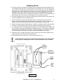
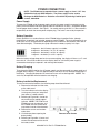
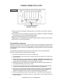
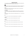
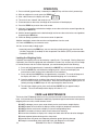
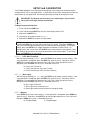
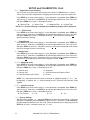
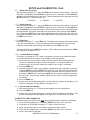
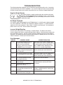
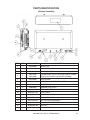
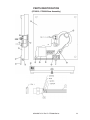
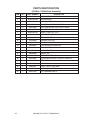
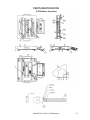
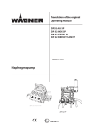
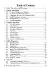
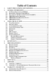
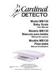
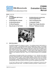
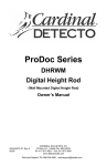
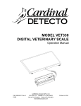
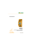
PZ3000 Series
Ingredient Scale
Owner’s Manual
8528-M372-O1 Rev D
01/10
CARDINAL SCALE MFG. CO.
PO BOX 151 • WEBB CITY, MO 64870
PH (417) 673-4631 • FAX (417) 673-5001
www.detectoscale.com
Technical Support: Ph: 866-254-8261 • [email protected]
Printed in USA
INTRODUCTION
TABLE OF CONTENTS
We wish to thank you for your purchase of our SPECIFICATIONS . . . . . . . . . . . . . . . . . . . . . . . 1
PZ3000 Ingredient scale. It has been designed INSTALLATION . . . . . . . . . . . . . . . . . . . . . . . . . 3
and manufactured at our factory in Webb City,
POWER CONNECTION . . . . . . . . . . . . . . . . . . 4
MO U.S.A. with quality and reliability.
Power Supply . . . . . . . . . . . . . . . . . . . . . . . . . 4
This manual will instruct you in the proper
Battery Operation . . . . . . . . . . . . . . . . . . . . . 4
installation, operation and maintenance of your
Battery Charging . . . . . . . . . . . . . . . . . . . . .. 4
new scale. Please read it before attempting to
Battery Installation/Replacement . . . . . . . . 4
use the scale and keep it handy for future
reference.
Extended Battery Operation . . . . . . . . . . . . 6
OPTIONAL ZERO DEVICES . . . . . . . . . . . . . . 7
FCC Compliance Statement
KEYPAD DESCRIPTION . . . . . . . . . . . . . . . . . 8
WARNING! This equipment generates uses
ANNUNCIATORS . . . . . . . . . . . . . . . . . . . . . . . 9
and can radiate radio frequency and if not
OPERATION . . . . . . . . . . . . . . . . . . . . . . . . . . . .10
installed and used in accordance with the
instruction manual, may cause interference to CARE and MAINTENANCE . . . . . . . . . . . . . . .10
radio communications. It has been tested and SETUP and Calibration . . . . . . . . . . . . . . . . . . .11
found to comply with the limits for a Class A
computing device pursuant to Subpart J of Part TROUBLESHOOTING . . . . . . . . . . . . . . . . . . .13
15 of FCC rules, which are designed to provide PARTS IDENTIFICATION . . . . . . . . . . . . . . . .14
reasonable protection against such
interference when operated in a commercial
environment. Operation of this equipment in a
SPECIFICATIONS
residential area may cause interference in
which case the user will be responsible to take Weight Display 6 Digit, 0.7" LCD
Digital Display
whatever measures necessary to correct the
interference.
Dimensions
You may find the booklet "How to Identify and Resolve
Radio TV Interference Problems" prepared by the
Federal Communications Commission helpful. It is
available from the U.S. Government Printing Office,
Washington, D.C. 20402, stock No. 001-000-00315-4.
All rights reserved. Reproduction or use,
without expressed written permission, of
editorial or pictorial content, in any manner, is
prohibited. No patent liability is assumed with
respect to the use of the information contained
herein. While every precaution has been taken
in the preparation of this manual, the Seller
assumes no responsibility for errors or
omissions. Neither is any liability assumed for
damages resulting from use of the information
contained herein. All instructions and diagrams
have been checked for accuracy and ease of
application; however, success and safety in
working with tools depend to a great extent
upon the individual accuracy, skill and caution.
For this reason the Seller is not able to
guarantee the result of any procedure
contained herein. Nor can they assume
responsibility for any damage to property or
injury to persons occasioned from the
procedures. Persons engaging the procedures
do so entirely at their own risk.
Display
Scale Base
PZ3015
PZ3015L
PZ3030
PZ3060
7.5" W x 1.5" D x 4.5" H
8" W x 8" D x 1.75" H
12" W x 12" D x 1.75" H
12" W x 12" D x 1.75" H
14" W x 12" D x 3" H
Zero
Established on power up
routine and maintained by
auto-zero circuitry.
Power
Requirements
100 to 240 VAC 50/60Hz 12
VDC 1A wall plug-in UL/CSA
listed AC power adapter
(Cardinal part number
6800-1045) OR optional 6 “AA”
NiMH batteries (1.2v/2700
mAh). NOTE! On PZ3060, the
batteries (Cardinal part number
6800-0020) ARE included.
Tare
ZERO key on keypad, Lite Way
Sensor or optional Foot Switch
or Piezo Button
Operation
Temperature
30 to 110 °F (-1 to 43 °C)
Humidity
75% without condensation
Capacity
15lb x 0.005
30lb x 0.01
60lb x 0.02
Certifications
NOT LEGAL FOR TRADE
8528-M372-O1 Rev D • PZ3000 Series
1
Serial Number_______________________
Date of Purchase ____________________
Purchased Form_____________________
___________________________________
___________________________________
RETAIN THIS INFORMATION FOR FUTURE USE
PRECAUTIONS
Before using this instrument, read this
manual and pay special attention to all
"WARNING" symbols:
IMPORTANT
ELECTRICAL
WARNING
2
8528-M372-O1 Rev D • PZ3000 Series
INSTALLATION
1. Carefully remove the scale base and display from the shipping carton and inspect them for
any evidence of damage (such as exterior dents and scratches) that may have taken place
during shipment. Remove the packing material from the scale base and on the PZ3030, the
shipping screw on the bottom of the scale base. Next, remove the protective covering from
the display and keypad. Keep the carton, packing material and shipping screw (on the
PZ3030) for return shipment if it should become necessary. NOTE! It is the responsibility of
the purchaser to file all claims for any damages or loss incurred during transit.
2. To mount the display on the scale base, locate the two mounting screws on the display and
the two slotted holes in the scale base bracket.
3. Lift the scale (by the bracket) high enough to allow you to align the two screws on the
display with the large end of the two slotted holes in the bracket. Place the screws on the
display in the bracket and gently pull forward to secure the display to the bracket.
4. Plug the AC power supply into the power jack, located on the bottom side of the display (refer
to Figure 1) and then connect the AC power adapter into the proper electrical outlet.
5. If it is desired to use the scale remotely (no AC power), with the exception of the PZ3060, you
must first obtain and install 6 NiMH batteries (2300mAh minimum). The batteries should then
be allowed to charge approximately 8 hours. Charging the batteries for more than 8 hours
will not harm them. The scale may be operated while the batteries are charging.
6. Place the scale on a stable, vibration-free, level surface away from direct sunlight and any
rapidly moving air source (heating and cooling vents).
7. Place commodity tray on the scale. The scale is now ready to use.
DO NOT place the scale on an unstable cart, stand or table. The scale may fall
causing injury or damaging the scale, or proper operation may be inhibited.
Display
Mounting
Screws
Optional
Zero Device
Connector
Power
Supply
Jack
Scale
Base
Cable
Figure No. 1
8528-M372-O1 Rev D • PZ3000 Series
3
POWER CONNECTION
NOTE! The PZ3000 can be operated from a power supply or from 6 “AA” size,
(2300mAh minimum) NiMH batteries. The power supply is also used to
recharge the NiMH batteries. Batteries are available by ordering Cardinal part
number, 6800-0020.
Power Supply
To power the PZ3000 using the power supply, connect the power supply’s connector into the
power jack on the bottom side of the display and then connect the 12 VDC, 1 Amp power adapter
into the proper electrical outlet. See Figure 1. On models requiring 220 VAC, it is the customer’s
responsibility to obtain the correct power adapter plug. The scale is now ready for operation.
Battery Operation
Battery operation is a standard feature of the PZ3000 Series Ingredient Scale, although
the batteries are optional (not included, except on model PZ3060). The scale will operate for up
to 50 hours on fully charged batteries depending on the condition of the batteries (from new to
about 500 recharges). The battery bar graph indicates the battery capacity in 4 steps:
4 segments - the full battery capacity is available,
3 segments - the battery is at 75% of capacity,
2 segments - the battery is at 50% of capacity,
1 segment: - the battery is at 25% capacity.
When the battery voltage drops too low for accurate weighing, the display will show !6; and
then shut off. You will be unable to turn the display back on until the AC power supply is
connected to the display to operate it and recharge the batteries.
Battery Charging
To recharge the NiMH batteries, the AC power supply must be connected to a power outlet and
plugged into the display. It will take approximately 4 to 8 hours to fully recharge the batteries in
the display. Charging the batteries for more than 8 hours will not damage them. NOTE! The
scale may be operated while the batteries are charging.
Battery Installation/Replacement
To install or remove the batteries, the following steps should be followed:
1. Remove the indicator from the scale,
wall or table stand.
2. Turn the indicator so that the display
is facing away from you and place it
face down on a table or bench.
3. Referring to Figure No.2, locate the
two screws on the angled edge of
indicator. NOTE! The PZ3015 and
PZ3030 use two thumbscrews and
the PZ3060 uses two socket head
cap screws instead of thumbscrews.
4. Remove the screws and washers
under them.
5. Lift the battery door exposing the
battery holder.
6. Referring to Figure No. 3, locate and
remove the connector on the end of
the battery holder.
4
Remove these Screws
8528-M372-O1 Rev D • PZ3000 Series
Figure No. 2
POWER CONNECTION, CONT.
7. Slide one side of the battery door so that it clears the edge of the indicator enclosure and
then remove the battery door.
8. Place the battery door on a table or bench with the battery holder and battery strap up.
9. Referring to Figure No. 3, remove the 2 Philips screws securing the battery strap to the
battery door and remove the strap.
Battery Strap
Battery
Connector
Figure No. 3
Remove Philips Screws
10. To install or replace the batteries, first remove the battery holder cover by pushing in on
the tab and lifting it up. Refer to Figure No. 4.
11. If replacing the batteries, remove all 6 batteries from the battery holder. If installing new
batteries, proceed to step 12.
NOTE! To insure optimum performance of your PZ3000 when powered by the
internal battery, replace all 6 batteries with new “AA” size, NiMH batteries
(2300mAh minimum). DO NOT mix new and used batteries.
Figure No. 4
Battery
Cover
Push in and
lift here
12. Install the 6 new “AA” size batteries in the battery holder, noting the polarity markings
located in the battery holder. Refer to Figure No. 5.
13. After placing all 6 batteries in the holder, replace the battery cover and battery strap.
Secure the battery strap with the 2 Philips screws removed earlier.
14. Replace the battery door on the indicator and then re-connect the connector on the end of
the battery holder.
8528-M372-O1 Rev D • PZ3000 Series
5
POWER CONNECTION, CONT.
Figure No. 5
-
+
+
-
-
+
+
-
-
+
+
-
6 “AA” Size NiMH Batteries
(2300mAh minimum)
15. Insuring no wires are between the battery door and the back of the indicator, lower the
battery door.
16. Install the two screws and washers removed in step 4. NOTE! The PZ3015 and PZ3030
use thumbscrews and should be finger-tightened only.
17. Return the indicator to the scale, wall or table stand.
18. Apply power to the PZ3000 using the power supply, to begin charging the new batteries.
19. The scale is now ready for operation.
Extended Battery Operation
In operations that require the remote use (no AC power) of the scale beyond the approximately
50 hours of continuous use, an auxiliary battery door assembly (CPN 8528-C365-0A) and 6 “AA”
size, 2300 mAh minimum batteries (CPN 6800-0020) can be purchased to easily accommodate
your operation.
The following steps describe how to remove the battery door and re-charge the batteries
externally using the AC power adapter (battery charger).
1. Remove the indicator from the scale, wall or table stand.
2. Turn the indicator so that the display is facing away from you and place it face down on a
table or bench.
3. Referring to Figure No.2, locate the two screws on the angled edge of the indicator and
remove the screws and washers under them. NOTE! The PZ3015 and PZ3030 use two
thumbscrews and the PZ3060 uses two socket head cap screws.
4. Referring to Figure No. 6 remove the connector from the end of the battery holder and
then remove the battery door and set it aside.
5. Place the auxiliary battery door with fully recharged batteries on the indicator and then
re-connect the connector to the end of the battery holder. See Figure No. 6.
6. Insuring no wires are between the battery door and the back of the indicator, lower the
battery door and install the two screws and washers removed in step 3. NOTE! The
PZ3015 and PZ3030 use thumbscrews and should be finger-tightened only.
7. Return the indicator to the scale, wall or table stand. The scale is ready for operation.
8. Place the battery door removed in step 5 on a table or bench with the battery holder and
battery strap up.
6
8528-M372-O1 Rev D • PZ3000 Series
POWER CONNECTION, CONT.
9. Referring to Figure No. 6, locate the battery charger jack on the battery door.
10. Plug the AC power adapter (battery charger) into the jack on the battery door and then
connect the AC power adapter (battery charger) into the proper electrical outlet.
11. Allow approximately 4 to 8 hours to fully recharge the batteries.
Battery
Connector
Figure No. 6
Battery
Charger
Jack
OPTIONAL ZERO DEVICES
In addition to the standard display pushbutton and “Lite Way” hands-free methods to zero the
weight, the PZ3000 Series has an optional Foot Pedal or Mountable Pushbutton available. The
model numbers for the optional zero devices are:
x
PZFS for the foot pedal and
x
PZPB for the mountable pushbutton.
Figure No. 7
Power
Supply
Jack
Scale
Base
Cable
8528-M372-O1 Rev D • PZ3000 Series
Optional
Zero Device
Plugs in Here
7
KEYPAD DESCRIPTION
The PZ3000 display is equipped with a membrane keypad containing 3 keys and the LITE-WAY
photo-eye sensor. The keypad is shown in detail in Figure 8.
Figure No. 8
DO NOT operate the keypad with pointed objects (pencils, pens, etc).
Damage to keypad resulting from this practice is NOT covered under warranty.
The following describes the use of each key.
Pressing this key will apply power to the instrument and turn on the scale. Note
that you must press and hold the key for approximately 2 seconds for the scale to
power up. If the scale is already on, pressing this key quickly will turn the scale off.
This key is also used to lock the weighing units. Refer to the “Operation” section of
this manual for instructions on locking the weighing units.
This key is used to select the units in which the weight is to be displayed. The
available units include pounds only, ounces only, pound-ounces with fraction,
kilograms, pound-ounces with decimal point and grams.
Pressing this key when the scale is on will zero the scale.
With the /,7(:$< photo eye enable in setup ($,6;6`)`>` or ), passing your
hand over the photo eye sensor will cause the scale to zero.
Photo Eye
8
8528-M372-O1 Rev D • PZ3000 Series
ANNUNCIATORS
The annunciators are turned on to indicate that the display is in the mode corresponding to the
annunciator label or that the status indicated by the label is active.
The low battery annunciator is located in the upper left corner of the display. It is used to indicate
the battery status. Refer to the Power Connection section of this manual for more details.
GROSS
This annunciator is turned on to show that gross weight is displayed. Gross weight will be
displayed when no tare weight is stored.
[\ (STABLE)
This annunciator is turned on when the weight display is stable. When off, it means that the
change in successive weight samples is greater than the motion limits selected during setup.
ZERO
This annunciator is turned on to indicate that the weight displayed is within +/- 1/4 division of the
center of zero.
kg
This annunciator is turned on to indicate the weight displayed is in kg (kilograms).
POUNDS
This annunciator is turned on to indicate the weight displayed is in pounds.
OUNCES
This annunciator is turned on to indicate the weight displayed is in ounces.
3/4
This annunciator is turned on to indicate the weight displayed is to the nearest 3/4 ounce.
1/2
This annunciator is turned on to indicate the weight displayed is to the nearest 1/2 ounce.
1/4
This annunciator is turned on to indicate the weight displayed is to the nearest 1/4 ounce.
8528-M372-O1 Rev D • PZ3000 Series
9
OPERATION
1. Press and hold (approximately 2 seconds) the ON/OFF key until the scale is powered up.
2. With no weight on the scale, press the ZERO key. 1
3. After a brief moment, the display will show
4. The scale is now “zeroed” and ready for use.
`
5. Place container on the scale, the weight of the container will be displayed.
6. Press the ZERO key to return the scale to zero.
7. Add your first ingredient to the desired weight; re-zero the scale for the second ingredient by
pressing the ZERO key.
8. Add the second ingredient to the desired weight and re-zero the scale for the next ingredient
by pressing the ZERO key.
9. Continue adding ingredients in the same manner of operation.
10. After completion, remove the container and ingredients from the scale.
11. Press the ZERO key to re-zero the scale.
12. You are now ready to begin again.
1
Instead of pressing the ZERO key, you can zero the scale by passing your hand over the
“Lite Way” photo eye (if enabled) or with the optional Foot Switch (PZFS) or the mountable
Pushbutton (PZPB).
Locking the Weighing Units
If desired, the weighing units can be locked to a specific unit. For example, if during Setup and
Calibration, the scale was configured and calibrated in Pounds Only and you only want to weigh
in Pounds/Ounces with the Fraction displayed, you would need to perform the following:
1. Press and hold (approximately 2 seconds) the ON/OFF key until the scale is powered up.
2. Press the UNITS key until the desired weighing units is shown on the display (the
annunciators and/or fraction for the desired unit are turned on).
3. Press and hold the ON/OFF key for approximately 2 seconds. The scale will beep and
the display will show !6, indicating the selected weighing unit is now locked.
4. Once the weighing units are locked, the scale will always power up in the locked units and
not in the units the scale was calibrated in. Note that even though the weighing units are
locked, pressing the UNITS keys will still step through the alternate units.
5. To unlock the weighing units, press and hold the ON/OFF key for approximately 2
seconds. The scale will beep and the display will show '0!6.
CARE and MAINTENANCE
The heart of the PZ3000 Ingredient scale is a precision load cell located in the center of the scale
base. It will provide accurate operation indefinitely if protected against overload of scale capacity,
dropping items on scale, or other extreme shock.
DO NOT submerge, pour or spray water directly on the scale base or weight display.
DO NOT expose the scale base or display to direct sunlight or temperature extremes.
DO NOT place the scale base or display in front of heating/cooling vents.
DO NOT use acetone, thinner or other volatile solvents for cleaning.
DO clean the scale base or display with a damp soft cloth and mild non-abrasive detergent.
DO remove power before cleaning with a damp cloth.
DO provide clean AC power and adequate protection against lightning damage.
DO keep the surroundings clear to provide clean and adequate air circulation.
10
8528-M372-O1 Rev D • PZ3000 Series
SETUP and CALIBRATION
Your PZ3000 Ingredient scale has been pre-configured at the factory and should not require
configuration for use in most applications. In the event that the factory settings do not meet the
requirements of your application, the following describes the steps to configure the scale.
IMPORTANT! The display and scale base are a matched pair. Do not switch
them (refer to S/N tags) without recalibration.
To Begin Setup and Calibration:
1. Press and hold the ZERO key.
2. Press and hold the ON/OFF key until the scale display shows .
3. Release the ON/OFF key.
4. The display will change to show 8,6;6)>.
5. Release the ZERO key to enter the setup mode.
During setup and calibration it will be necessary to enter data using the scale’s keyboard.
Pressing the ZERO key will show the current value of a setting. Pressing the ZERO key
again will save the displayed setting value and advance to the next prompt. To change a
setting, press the UNITS key to "toggle" between the different available values. On
settings with 2 digit values, press the ON/OFF key to advanced to the next position. Note
that the blinking character is the cursor location of the value to be changed. To exit setup,
press the ON/OFF key at any prompt.
$,6;6)>`(LITE WAY Photo Eye)`
With the display showing 8,6;6)>, press the ZERO key to show the current setting. If the
value displayed is acceptable, press the ZERO key again to save it. Otherwise, use the
UNITS key to step through the selections for a new value. When the desired value is
displayed, press the ZERO key to save it. Allowable values are:
0 = Wavy Zero Turned Off
1 = Wavy Zero intensity set to 0 to 2 inches
2 = Wavy Zero intensity set to 6 inches maximum
`!&>`(Back Light)`
With the display showing 217`/;>, press the ZERO key to show the current setting. If the
value displayed is acceptable, press the ZERO key again to save it. Otherwise, use the
UNITS key to step through the selections for a new value. When the desired value is
displayed, press the ZERO key to save it. Allowable values are:
0 = Back Light Turned Off
1 = Back Light set to continuously on
2 = Back Light comes on after key press or change in weight
$>`(Beeper)`
Press ZERO key to show current setting. If value displayed is acceptable, press ZERO key
again to save it. Otherwise, use UNITS key to step through selections for a new value and
then press ZERO key to save it. Allowable values are:
0 = Disable Beeper
1 = Enable Beeper
8528-M372-O1 Rev D • PZ3000 Series
11
SETUP and CALIBRATION, Cont.
!&>`(Digital Filter Level Selection)
Your scale will arrive with factory filter settings of 0 = Minimal (PZ3060 will be 2 = Heavy).
Please check with Tech Support before changing filter level, break range and sample rate.
Press ZERO key to show current setting. If value displayed is acceptable, press ZERO key
again to save it. Otherwise, use UNITS key to step through selections for a new value and
then press ZERO key to save it. Allowable values are:
0 = Minimal Filter
2 = Heavy Filter
1 = Moderate Filter
3 = Custom Filter
NOTE! If 3 = Custom Filtering is selected, three additional prompts will be displayed.
`
!&!'!> (Filter Level)`
Press ZERO key to show current setting. If value displayed is acceptable, press ZERO key
again to save it. Otherwise, use UNITS key to step through selections for a new value and
then press ZERO key to save it. Allowable values are 1 (least amount of filtering) to 99
(greatest amount of filtering).
%`> (Break Range)
Press ZERO key to show current setting. If value displayed is acceptable, press ZERO key
again to save it. Otherwise, use UNITS key to step through selections for a new value and
then press ZERO key to save it. Allowable values are 1 to 99 which correspond to the number
of division changes to break out of filtering.
*%> (Sample Rate)
Press ZERO key to show current setting. If value displayed is acceptable, press ZERO key
again to save it. Otherwise, use UNITS key to step through selections for a new value and
then press ZERO key to save it. Allowable values are a minimum of 1 sample per second to a
maximum of 16 samples per second in one sample per second intervals.
'")&*> (Weighing Units)
Press ZERO key to show current setting. If value displayed is acceptable, press ZERO key
again to save it. Otherwise, use UNITS key to step through selections for a new value and
then press ZERO key to save it. Allowable values are:
1 = Pounds Only
2 = Ounces Only
3 = Pounds/Ounces with Fraction
4 = Kilograms
5 = Pounds/Ounces with Decimal Point
6 = Grams
NOTE! If 3 = Pounds/Ounce with Fraction is selected, an additional prompt ( 917;> ) will
be displayed. In addition, the -0; (Interval Setting) and 3$$ (Decimal Point Position) will be
skipped.
%&> (Fraction Interval)
Press ZERO key to show current setting. If value displayed is acceptable, press ZERO key
again to save it. Otherwise, use UNITS key to step through selections for a new value and
then press ZERO key to save it. Allowable values are:
0 = No Fraction
2 = 1/2
4 = 1/4
8 = 1/8
-0;>`(Interval Setting)`
With the display showing -0;>, press the ZERO key to show the current setting. If the value
displayed is acceptable, press the ZERO key again to save it. Otherwise, use the UNITS key
to step through the selections for a new value. When the desired value is displayed, press the
ZERO key to save it. Allowable values are: 1, 2, or 5.
12
8528-M372-O1 Rev D • PZ3000 Series
SETUP and CALIBRATION, Cont.
3$$>`(Decimal Point Position)`
With the display showing 388>, press the ZERO key to show the current setting. If the value
displayed is acceptable, press the ZERO key again to save it. Otherwise, use the UNITS key
to step through the selections for a new value. When the desired value is displayed, press the
ZERO key to save it. Allowable values are:
1= XXXXX.X
2 = XXXX.XX
3 = XXX.XXX
$>`(Scale Capacity)
With the display showing $>, press the ZERO key to show the current setting. If the value
displayed is acceptable, press the ZERO key again to save it. Otherwise, use the UNITS key
and the ON/OFF key to select the capacity. Note that the cursor location is identified by the
blinking character and can be advanced to the next position (left) by pressing the ON/OFF
key. Pressing the UNITS key will change the blinking character to the next value. Verify that
the numbers selected are the same as the weight listed on the capacity label and then press
the ZERO key to save it.
!> (Calibration)
With display showing !>, press ZERO key. The display will change to show current setting
(0 = NO, skip calibration). If scale has been previously calibrated and you wish to skip
calibration and proceed to Store Setup and Calibration, press ZERO key again.
To begin calibration, press UNITS key to select 1 (YES, calibrate scale) and then press ZERO
key. Display will change to !#3>.
!#3>`(Load Calibration Weight)
The display will change to !#3> which is a prompt for the entry of the calibration weight
value and placement of this amount of test weights on the scale platform.
1. Make certain the scale platform is empty and free of debris, then place the desired
amount of calibrated test weights on the scale platform. It is recommended that a
minimum of 50% of the scale’s capacity be used but 70% to 100% is preferred.
2. Press the ZERO key.
3. Determine the exact amount of test weights to be placed on the scale platform and then
using the UNITS key and the ON/OFF key select this value. Note that the cursor location
is identified by the blinking character and can be advanced to the next position (left) by
pressing the ON/OFF key. Pressing the UNITS key will change the blinking character to
the next value. Verify that the numbers selected are the same as the total weight of the
test weights.
4. Press the ZERO key.
5. Starting at the left and proceeding right, a series of dashes will appear on the display. The
dashes will disappear and the display will change to '0!3.
'0!3`(Unload Calibration Weight)
1. With display showing '0!3, remove the test weights from the scale platform.
2. Press the ZERO key.
3. Starting at the left and proceeding right, a series of dashes will appear on the display. The
dashes will disappear and the display will change to 655 and the scale will turn off.
STORE SETUP AND CALIBRATION
To complete setup and calibration and store setup and calibration data, perform the following:
1.
2.
3.
4.
5.
Press and hold (approximately 2 seconds) ON/OFF key until scale is turned on.
The display will immediately change to 655 and the scale will turn off.
Setup and calibration data is now stored in scale’s nonvolatile memory.
Press and hold (approximately 2 seconds) ON/OFF key until scale is turned on.
Scale is now ready for operation.
8528-M372-O1 Rev D • PZ3000 Series
13
TROUBLESHOOTING
The following describes conditions you may encounter while operating this scale. Instructions
are provide to help you correct the problem. If you are still unable to resume normal operating
functions, please contact your nearest scale technician or our Technical Support Department.
Negative Weight Display
@ The scale will display a negative weight when the scale base has been
emptied or partially emptied without re-zeroing the scale. To re-zero the
scale, press the ON/ZERO key, wait for the display to read zero, and start
the procedure again.
No Weight Displayed
Is the power supply cable plugged into the PZ3000 display? Is the AC power adapter plugged
into a wall receptacle? Check the wall receptacle for proper AC power. Try another electrical
appliance in the same receptacle. Does it work? Check the circuit breaker. Has there been a
power failure of any kind? Are the batteries discharged?
Incorrect Weight Reading
Insure that the scale platform isn’t touching an adjacent object. The display will show an
incorrect weight when there is a product buildup under the platter. Clean the platter and place on
the scale platform securely. Test with a known amount of weight to see if the correct weight is
displayed. Have proper operation procedures been followed? If problem persists, the scale may
need re-calibration. Contact your scale serviceman.
Error Messages
DISPLAY
POSSIBLE CAUSE
CORRECTIVE ACTION
'0*;` This message indicates that motion Insure scale is on a stable, vibration-free,
is present when attempting to
perform one of the following
operations: Power Up or Pressing
the ON/OFF key on the keypad
@6@` This message indicates an attempt
to display a negative weight greater
than -9 lb 15 oz.
level surface away from any rapidly moving
air source (such as heating and cooling
vents). NOTE! When attempting to zero
scale, wait for a stable weight display.
Insure the scale is at zero. If problem
persists, contact your scale serviceman.
@6!@` This message indicates the weight
Remove the weight from the scale platform.
on scale exceeds the scale capacity. Insure the scale is at zero. If problem
persists, contact your scale serviceman.
!2` This message indicates that the
Contact your scale serviceman.
scale needs calibration.
99!` The load cell input is below the range Remove power, and then reapply power.
of the indicator.
99` The load cell input is above the
If problem persists, contact your scale
serviceman.
range of the indicator.
99` This message indicates the display
is not receiving the signal from the
scale base.
Inspect the scale cable and connector for
damage. If problem persists, contact your
scale serviceman.
6` This message is displayed to
indicate the scale is turning off.
14
8528-M372-O1 Rev D • PZ3000 Series
PARTS IDENTIFICATION
(Display Assembly)
ITEM
QTY
PART NUMBER
DESCRIPTION
1
1
593GR986
SERIAL TAG
2
4
6013-0039
NUT HEX #6-32
3
2
6021-0661
SCW PAN HEAD #6-32 X .25 X S.S.
4
2
6021-1032
THUMB SCRW, 6-32 X 0.25 (PZ3015, 3015L & 3030)
6021-0300
SCW SOCKET HEAD CAP SCREW (PZ3060)
5
2
6610-2000
JACK SOCKET
6
6
6680-0004
WASHER LOCK INT. TOOTH #6 Z/P
7
4
6680-0045
SPACER (PCB) #6 X .250
8
2
6680-0052
WASHER LOCK #4 Z/P
9
1
6980-0015
STRAIN RELIEF BUSHING SR 5N-4 BLACK
10
1
8528-B377-0A
ZERO CABLE
11
1
8528-B378-0A
LOAD CELL CABLE
12
1
8528-B379-0A
DC POWER CABLE
13
1
8528-C365-0A
BATTERY DOOR ASSEMBLY
14
1
8528-C366-0A
ENCLOSURE WELDMENT
15
1
8528-D351-08
KEYPAD
16
1
8528-D359-0A
PCB ASSEMBLY
8528-M372-O1 Rev D • PZ3000 Series
15
PARTS IDENTIFICATION
(Battery Door Assembly)
ITEM
QTY
PART NUMBER
DESCRIPTION
1
3
6013-0039
NUT HEX #6-32
2
2
6021-0654
SCW PAN HEAD #6-32 x .250 PDMS
3
2
6021-0687
SCW TRUSS HEAD #6-32 x .312 THMS
4
3
6680-0004
WASHER LOCK INT. TOOTH #6 Z/P
5
1
8528-B272-08
LABEL: BATTERY REQ. PZ2500
6
1
8528-B364-0A
BATTERY DOOR WELDMENT
7
1
8528-B391-08
BATTERY RETAINER
8
1
8528-C374-0A
BATTERY PACK ASSEMBLY
9
2
8555-B159-08
SPACER, 758C MOUNT
½
1
6800-1045
AC ADAPTER, 100-240VAC/12VDC @ 1 AMP
½
6
6800-0020
BATTERY, NiMH 1.2V/2700mAH, AA SIZE
(Included on PZ3060)
(Optional on PZ3015, PZ3015L & PZ3030)
½ Not Shown
16
8528-M372-O1 Rev D • PZ3000 Series
PARTS IDENTIFICATION
(PZ3015 Base Assembly)
8528-M372-O1 Rev D • PZ3000 Series
17
PARTS IDENTIFICATION
(PZ3015 Base Assembly)
ITEM
QTY
PART NUMBER
1
1
428R1079
DECAL
2
1
427R1366
COMMODITY TRAY
3
1
427R1365
WEIGHBRIDGE
4
1
8528-B110-0A
5
2
587R9378
LOAD CELL SPACER
6
2
6021-1124
#10-32 X .75 SOC HD S.S.
7
1
6021-1258
#10-32 X .375 SET SCW
8
2
6021-1074
#10-32 X .5 FHMS S.S.
9
1
6560-0021
LOCTITE
10
1
593GR986
SERIAL TAG
11
4
6540-1004
RUBBER FOOT
12
1
6610-3000
CONNECTOR HOUSING
13
1
6980-0004
STRAIN RELIEF
14
1
8528-B392-0A
15
1
6610-5007
CABLE CLIP
16
1
8534-C623-0A
SCALE BASE
17
4
6540-1058
RUBBER PAD
18
1
593R1021
LABEL
18
DESCRIPTION
LOAD CELL ASSY.
CABLE: LOAD CELL (9 FT)
8528-M372-O1 Rev D • PZ3000 Series
PARTS IDENTIFICATION
(PZ3015L, PZ3030 Base Assembly)
8528-M372-O1 Rev D • PZ3000 Series
19
PARTS IDENTIFICATION
(PZ3015L, PZ3030 Base Assembly)
ITEM
QTY
PART NUMBER
1
1
8528-C262-0A
BASE PLATE WELDMENT
2
1
8528-D264-08
WEIGHBRIDGE
3
1
8528-D263-08
COMMODITY TRAY
4
1
8528-B110-0A
LOAD CELL ASSEMBLY DF-50T
5
2
6021-2003
FLAT HEAD SCREW .625 SOCKET HEAD
6
4
6540-1058
RUBBER PAD
7
1
8528-B392-0A
CABLE: LOAD CELL (9 FT)
8
4
6540-1004
RUBBER FEET STICK ON
9
1
6980-0004
STRAIN RELIEF
10
1
6610-3000
CONNECTOR PLUG
11
3
587R9378
SPACER LOAD CELL
13
2
6024-0037
LOCK WASHER #10 HELICAL
14
1
6021-2002
THUMB SCREW #10-32 X 3/4”
15
1
8529-B045-08
16
1
593GR986
SERIAL TAG
17
1
6650-0087
STICKER MADE IN USA
18
2
6021-2001
CAP SCREW #10-32 X 1” SOCKET HEAD S.S.
19
1
6021-1258
SET SCREW #10-32 X .375
21
1
6610-5007
CABLE CLIP
22
1
593R1021
LABEL “NOTCH THIS SIDE”
23
1
428R1079
LABEL PZ SCALE DECAL
24
1
6024-1484
FLAT WASHER #10 S.S.
20
DESCRIPTION
LABEL REMOVE
8528-M372-O1 Rev D • PZ3000 Series
PARTS IDENTIFICATION
(PZ3060 Base Assembly)
8528-M372-O1 Rev D • PZ3000 Series
21
PARTS IDENTIFICATION
(PZ3060 Base Assembly)
ITEM
QTY
PART NUMBER
1
1
1961-B006-08
LABEL, DETECTO
2
1
1961-D002-08
BASE PLATE
3
1
1961-D004-08
WEIGHBRIDGE
4
1
1961-D005-08
COMMODITY TRAY
5
1
2950-C121-4A
LOAD CELL TSP-100KG
6
1
593GR986
SERIAL TAG ASSEMBLY
7
2
6007-0009
HEX HEAD BOLT 1/4-20 X 1/2” Z.P.
8
4
6007-0011
BOLT, HEX HEAD 1/4-20 X 1” Z.P.
9
10
6013-0045
NUT, HEX 1/4-20
10
4
6021-1013
#10-32 X .375 RHMS
11
4
6021-1429
1/4-20 X 0.75 SHCS
12
6
6021-1454
SCREW, HEX HEAD 1/4-20 X 0.75
13
2
6450-0001
RUBBER FOOT, 0.5 SQ X 0.23 HIGH, WHT, ADHES
14
4
6024-0037
WASHER, LOCK #10 HELICAL SPLIT
15
10
6024-0040
WASHER LOCK HELICAL 1/4 S.S.
16
4
6540-1058
RUBBER PAD
17
4
6540-1130
LEVELING FOOT
18
7
6610-5007
CABLE CLIP
19
1
6680-1091
RUBBER GROMMET
20
1
8528-C381-08
INDICATOR MOUNTING BRACKET, FRONT
21
0
8528-D367-1A
DISPLAY ASSEMBLY
22
6
8540-B454-08
1/4-20 SPACER X 1/2 O.D. X 1”
23
2
8528-B274-08
HANDLE
24
1
6610-3000
25
1
8528-B392-1A
26
1
428R1079
22
DESCRIPTION
CONNECTOR PLUG #03-06-2042
CABLE: LOAD CELL (9 FT)
PZ SCALE DECAL
8528-M372-O1 Rev D • PZ3000 Series
NOTES
8528-M372-O1 Rev D • PZ3000 Series
23
STATEMENT OF LIMITED WARRANTY
Detecto Scale warrants its equipment to be free from defects in
material and workmanship as follows: Detecto warrants to the original
purchaser only that it will repair or replace any part of equipment
which is defective in material or workmanship for a period of one
(1) year from date of shipment. Detecto shall be the sole judge of
what constitutes a defect.
During the first ninety (90) days Detecto may choose to supply all
necessary replacement parts and service during normal weekday
working hours at no charge to the buyer.
After the first ninety (90) days Detecto will supply parts and service
at the job site provided the owner agrees to pay the Dealer for all
travel time, including mileage and test equipment, as well as any
expenses incurred over the direct labor of the technician at the job
site. This limited warranty honors only labor performed by Detecto
authorized dealers.
This warranty does not apply to peripheral equipment not
manufactured by Detecto; this equipment will be covered by certain
manufacturer’s warranty only.
This warranty does not include replacement of expendable or
consumable parts. This does not apply to any item which has
deteriorated or damaged due to wear, accident, misuse, abuse,
improper line voltage, overloading, theft, lightning, fire, water or acts
of God, or due to extended storage or exposure while in purchaser’s
possession. This warranty does not apply to maintenance service.
Purchased parts will have a ninety (90) day repair or replacement
warranty only.
Detecto may require components be returned to the factory; they
must be properly packed and shipping charges prepaid. A return
authorization number must be obtained for all returns and marked on
the outside of all returned packages. Detecto accepts no
responsibility for loss or damage in transit.
24
8528-M372-O1 Rev D • PZ3000 Series
STATEMENT OF LIMITED WARRANTY
Conditions Which Void Limited Warranty
This warranty shall not apply to equipment which:
A.) Has been tampered with, defaced, mishandled or have had
repairs and modifications not authorized by Detecto.
B.) Has had serial number altered, defaced, or removed.
C.) Has not been grounded according to Detecto’s recommended
procedure.
Freight Carrier Damage
Claims for equipment damaged in transit must be referred to the
freight carrier in accordance with freight carrier regulations.
This warranty sets forth the extent of our liability for breach of any
warranty or deficiency in connection with the sale or use of the
product. Detecto will not be liable for consequential damages of any
nature, including but not limited to, loss of profit, delays or expenses,
whether based on tort or contract. Detecto reserves the right to
incorporate improvements in material and design without notice and
is not obligated to incorporate improvements in equipment previously
manufactured.
The foregoing is in lieu of all other warranties, express or implied
including any warranty that extends beyond the description of the
product including any warranty of merchantability or fitness for a
particular purpose. This warranty covers only those Detecto products
installed in the forty-eight (48) contiguous continental United States.
Ph. (800) 641-2008
E-mail: [email protected]
203 E. Daugherty
Webb City, MO 64870
8528-M372-O1 Rev D • PZ3000 Series
02/06
Printed in USA
D268-WARRANTY-DET
25
26
8528-M372-O1 Rev D • PZ3000 Series