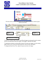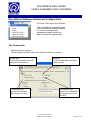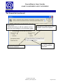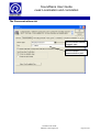
1
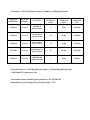
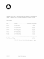
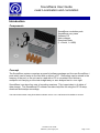
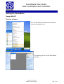
Transmittal Haley and Ward, Inc. Civil and Environmental Engineers 63 Great Road Maynard, MA 01754 (978) 648-6025 (office) (978) 648-6068 (fax) To: Malcolm Harper Company: MassDEP CERO From: Greg Eldridge, Myles Killar Date: June 12, 2013 Re: Medway Water Conservation Grant, 10-05/WCG, Project Report Job #: MDY-107 Via: Mail: CC: Dave D’Amico Overnight: X For your information For your review For your signature Courier: Approved X Approved as noted Returned to you for correction Message: Enclosed you will find the Final Project Report for Medway. If you have any questions or concerns please feel free to contact me. MEDWAY WATER CONSERVATION GRANT PROJECT PROJECT NUMBER 10-05/WCG YEARS PROJECT CONDUCTED 2011-2013 PREPARED BY: MEDWAY DEPARTMENT OF PUBLIC SERVICES, WATER AND SEWER DIVISION AND HALEY AND WARD, INC. PREPARED FOR: MASSACHUSETTS DEPARTMENT OF ENVIRONMENTAL PROTECTION BUREAU OF RESOURCE PROTECTION AND U.S. ENVIRONMENTAL PROTECTION AGENCY REGION 1 MEDWAY WATER CONSERVATION GRANT PROJECT PROJECT NUMBER 10-05/WCG PREPARED BY: MEDWAY DEPARTMENT OF PUBLIC SERVICES, WATER AND SEWER DIVISION AND HALEY AND WARD, INC PREPARED FOR: MASSACHUSETTS DEPARTMENT OF ENVIRONMENTAL PROTECTION BUREAU OF RESOURCE PROTECTION AND U.S. ENVIRONMENTAL PROTECTION AGENCY REGION 1 EXECUTIVE OFFICE OF ENERGY & ENVIRONMENTAL AFFAIRS Richard K. Sullivan, Jr., Secretary DEPARTMENT OF ENVIRONMENTAL PROTECTION Kenneth L. Kimmell, Commissioner BUREAU OF RESOURCE PROTECTION Beth Card, Assistant Commissioner DIVISION OF MUNICIPAL SERVICES Steven J. McCurdy, Director This project has been financed partially with federal funds from the U.S. Environmental Protection Agency (USEPA) to the Massachusetts Department of Environmental Protection (MassDEP) under a Water Conservation Competitive Grant. The contents do not necessarily reflect the views and policies of EPA nor of MassDEP, nor does the mention of trade names or commercial products constitute endorsement or recommendation for use. Table of Contents Project Summary…………………………………………………………………………….……2 Successes……………………………………………………………………………………..….…4 Difficulties………………………………………………………………………...………………10 Lessons Learned…………………………………………………….………………………...…11 Recommendations for Follow-up to Project…………………………………………….……..12 Attachments………………………………………………………………………………..…….13 1 Project Summary The Medway Department of Public Services, Water and Sewer Division goals for the Water Conservation Grant were to promote water conservation, locate and repair leaks, identify and reduce unaccounted for water loss and water demand from the drinking water works and distribution system, especially during the summer months. The source of water supply is located within the Town of Medway; sufficient water supply is a current challenge. The project included replacing residential water meters, completing a comprehensive leak detection survey and conducting consequent leak repairs, and implementing an Outreach and Education program. Additionally, quarterly progress reports were completed. The funding source (grant monies versus Medway’s match or monies) are described in the ‘Successes’ section of the report. The tasks along with their deliverables, as outlined in the project scope, are defined below: Task 1: Leak Detection Survey Conduct a leak detection survey of the water mains and appurtenances of the water distribution system network. This task will consist of a comprehensive leak detection survey of 74 miles of main, hydrants, gate valves, and service connections. As part of the leak detection survey, use data loggers and a correlator to detect, record, analyze, and pinpoint the sound created by underground water leakage. Upon the identification of a leak, estimate the flow rate. After leaks are repaired, re-survey the repair sites to confirm that no other leaks remain. The survey was completed by Liston Utility Services. Task 2: Leak Repair Establish a priority system to implement leak repairs. Repairs will be performed in conformance with the Department’s water management act permit and with industry standards and will be documented with leak reports including estimates of leakage rates based on visual observation once infrastructure is exposed. This task is part of the Department’s match. Task 3: Public Outreach Program Encourage water conservation through the implementation of a robust public outreach and 2 education program and conservation policies. A water conservationist will conduct training on water conservation and outreach methods, which will be attended by Department of Public Services' administrators, Medway Water & Sewer Commissioners, and Water & Sewer Division operators and staff. An educational booth will be planned and staffed at the annual Medway Pride Day celebration by Water and Sewer Division personnel. This effort will include teaching practical steps about water conservation and distributing educational and conservation materials. Task 4: Meter Replacement Program Purchase and install up to fifty (50) new service meters, which will replace meters over ten (10) years old. Describe the selection process for choosing which meters to replace. Document the make, model, size, and number of particular meters replaced. Summarize the requisite savings from accurate billing statements as the result of replaced meters. This task is part of the Department’s match. 3 Successes The first and second tasks of the Water Conservation Grant required the Medway Department of Public Services, Water and Sewer Division to conduct a leak detection survey and follow-up with repairs. An experienced leak detection surveyor conducted a comprehensive leak detection survey of the entire distribution system, seventy-four (74) miles of water mains, with continuing support from the Department. Leak detection leads to reduced water loss, financial gains, increased system knowledge, and reduced disruption to customers, and is therefore essential to any conservation program. An overview of the pertinent system information the survey methodology and results can be found in the Leak Detection Survey Report, Attachment B. The report addresses the requirements for the leak detection survey and leak repair. The leak detection survey was funded through grant money supplied by MassDEP. Attachment A is the Leak Detection Survey Summary. Four leaks were service leaks; the other was a leaking hydrant. After the leaks were identified, their leakage was estimated. The combined estimated loss from the leaks was 36 gallons per minute (gpm). Following the repairs, the water savings was estimated at 51,840 gallons per day, or 18,921,600 gallons per year. Applying Medway’s cost to pump and treat water (storage, distribution, system operation and maintenance costs) of $0.00127/gallon, the annual water savings was approximately $23,900 which would have been lost revenue not to mention a wasted resource. This is a significant savings for any Department and illustrates the effectiveness of leak detection and more generally a water conservation program. Saving 18.9 million gallons each year is a significant amount of water not only for public water professionals, but for the public as well. Following the identification of the leaks, Medway promptly sent out a crew for repair. Leaks were repaired and the leak detection surveyor returned to the site and confirmed there was no longer any leakage. For more in depth information on any of the aforementioned subjects, please refer to the Leak Detection Survey Report, Attachment B. The table below summarizes the water and monetary savings attributed to water conservation grant 4 work, specifically leak detection and repair: Task Leak Detection & Repair Water Savings (gal/year) ($/year)* 18,921,600 $ 23,900 *The water savings in dollar amount were arrived at by applying Medway’s cost to produce and deliver water (as described above) of $0.00127 per gallon to the leakage found in the leak detection survey. The third successful task of the Water Conservation Grant was for Medway to conduct service meter replacement. Meter error data was obtained from a recently water audit, see Appendix C. Meter calibration was not part of the meter replacement work. The replacement work was funded by the Medway Department of Public Services, Water and Sewer Division as a financial match to the conservation grant. During the grant period, Medway replaced one hundred thirty-two (132) 5/8” residential service meters. All newly installed meters were the Department’s standard: Sensus Metering Systems. Service meters were replaced by age, oldest meters being the priority. Exceptions were when the meter failed (stopped) completely and was no longer registering flow. Accurate billing savings was calculated by applying the median residential water rate of $6.31 per 100 cubic feet to the unmetered flow associated with the 132 replaced meters. Based on a water audit previously conducted in Medway, 5/8” residential service meters under registered an average of 9.7%, see Appendix C. There are a total of 3,307 residential meters, therefore with 132 replaced, approximately 4.0% of the meters were replaced. The total volume delivered 260 million gallons per year (MGY) based on the Annual Statistical Report (ASR), therefore 10.4 MGY, or 1,345 ‘100 cubic feet’ were delivered through the 132 replaced meters. Applying the median water rate of $6.31 per 100 ft3 (or 746.3 gal), approximately $8,490 was saved due to accurate billing. A second calculation methodology confirms the quantity of water and monetary savings. Assuming a household size of four (4) and applying Medway’s ASR residential gallons per capita day of 63 (gallons/person/day), the 132 replaced service meters failed to meter approximately 12.1 million gallons annually. Extending this to a dollar amount, assuming the median water rate 5 employed by Medway of $6.31 per 100 ft3 (or 746.3 gal), the savings from accurate billing statements is over $10,160. The fourth task was to implement and enhance Medway’s Water Conservation Outreach and Education Program. This collaboration was funded partially by grant monies from MassDEP and partially by the Town of Medway as a financial match. A conservationist conducted training on water conservation outreach methods, and also planned to assist in outreach at the Department of Public Services' educational booth at the annual Medway Pride Day celebration. There were a total of fourteen attendees at the Outreach and Education training session including the Director and the Deputy Director of the Department of Public Services, a Water and Sewer (W&S) Commissioner, the W&S Superintendent and Assistant Superintendent, W&S operators and staff. The water conservationist spoke about how to reach out to existing local organizations and combine forces on water conservation education. It was explained how water conservation is a community effort wherein the water department, schools, and community organizations like the local garden club all play a vital role. Following the water conservation outreach training, the Department of Public Services' staff ran an educational water conservation booth of the Town’s annual festival, Medway Pride Day. Educational materials were distributed to the public. The grant monies funded educational materials, several hours of consultant assistance in the form of outreach implementation, while the Town funded all personnel hours. In the initial work scope, an elementary school visit was planned. Medway eliminated the school visit and in its place the Department of Public Services erected and manned an educational booth at the Town’s annual Medway Pride Day Festival. The festival is an existing annual event and the thought was that better results could be obtained and resources used more effectively by integrating outreach efforts into this established festival. 6 Difficulties Potential problems were minimal with this grant. Each task incorporated planning, management, and collaboration built into the performed work. Maintaining clear and effective communication between all involved parties proved difficult at times, but did not result in setbacks. 7 Lessons Learned One year was an appropriate amount of time to conduct a comprehensive leak detection survey, follow up leak repairs, perform meter replacement, and implement a public outreach and education program. Potential problems were minimal with this grant because each task incorporated planning and management built into the performed work. The leak detection survey was planned between the water superintendent and the leak detection surveyor. The Public Outreach and Education was conducted with participation between the Department of Public Services, the Medway Water & Sewer Commissioners, civil engineering management consultant Haley and Ward, Inc, and a water conservationist. To further improve the meter replacement program, a few recommendations can be made. Meter testing and calibration would be a very helpful component to add to the program, but it must be stressed that standards, such as AWWA’s, are modeled and followed strictly as discussed above. These industry standards have been refined over decades and will certainly improve any water utilities program and yield water savings. Additionally, service meter testing would be best conducted regularly throughout the year rather than being batched in large groups over large spans of time. With frequent testing, the training the operators receive will better be reinforced and retained. Finally, when each meter is tested the customer’s water use history should be recorded along with the meter error. The Department will be able to track how water use impacts meter error, and looking forward, incorporate this knowledge into their meter replacement program. 8 Recommendations There are several recommendations for each task, which if implemented, will improve recording of flows for sources of supply and distribution system measurement systems. Annual leak detection surveys are recommended to identify and subsequently repair leaks. The Department is encouraged to implement a routine hydrant maintenance and inspection program to check hydrants for unauthorized use and complete shutdown. Speaking generally about water loss and unaccounted for water, unmetered authorized uses and miscellaneous losses will always be difficult categories to quantify. Estimable sources of unmetered use such as fire fighting, bleeders, water main flushing, storage tank overflows, sewer system maintenance, street cleaning and construction can best be accounted for by working with the appropriate utility or department in developing and implementing quantification methodology. This can be achieved by working with management and stressing the importance of tight water use records. Still harder to quantify are unmetered miscellaneous losses such as bleeders, unauthorized connections and theft. A good strategy for keeping records in these instances would be first identifying each event that occurs, isolating it and estimating the water use as an individual occurrence. It is recommended that the successful elements of the Public Outreach and Education program be replicated annually such as the Medway Pride Day festival booth with education handouts. Maintaining relations and communication with local organizations is a great way to perpetuate Medway’s outreach program. Additionally, materials such as flyers and mailers could be distributed throughout the community. 9 Attachment A: 2011 Leak Detection Survey Summary and Reporting Forms DATE OF DETECTION DATE OF REPAIR LOCATION ESTIMATED LEAKAGE GPM ESTIMATED LEAKAGE GPD ESTIMATED LEAKAGE GPY 12/5/2011 12/12/12 10 Fisher St (Service Leak) 4 5,760 2,102,400 12/9/2011 12/17/12 7 Evergreen St (Service Leak) 10 14,440 5,256,000 12/9/2011 12/17/12 43 Lovering St (Service Leak) 10 14,400 5,256,000 12/12/2011 12/19/12 60 Winthrop St (Service Leak) 11 15,840 5,781,600 12/8/2011 12/17/12 15 Delmar Rd (Hydrant Leak) 1 1,440 525,600 Total estimated loss = 36 GPM (gallons per minute) = 51,840 GPD (gallons per day) = 18,921,600 GPY (gallons per year) Total annual volume of drinking water produced = 362,427,000 GPY Estimated loss as a percentage of total annual volume = 5.2% Attachment B: 2011 Water Distribution System Leak Detection Survey Methodology and Report *RADCOM SoundSens user guide available from manufacturer; direct web link not available. Attachment C: Residential Meter Error per a Previously Conducted Water Audit Residential meters in the Medway system include a basic water meter, usually located in the basement, and box register located outside the house. The outdoor register or “Box” provides the numbers that the meter reader records manually. The box shows total cubic feet in 100-cubic foot increments. The outdoor register operates through a wire connected to the meter inside the house. At every 100 cubic feet, a pulse is transmitted through the wire and the outdoor register indexes one digit. 41 data sets were tabulated and the outside reader compared to the inside meter. The difference between the two readings was calculated as a percentage of the inside meter reading. Within the 41 meters sampled the outdoor registers under read the metered volume by 9.7%. User Guide Radcom Technologies Ltd Sentry House 10 Romsey Industrial Park Greatbridge Road Romsey Hampshire UK SO51 0HR Tel: +44 (0)1794 528 700 Fax: +44 (0)1794 528 760 SoundSens User Guide Leak Localisation and correlation Record of Amendments Keep this record in the front of the User Manual. When the document has been amended write the amendment number, the date, the paragraph numbers affected by the amendment and your initials in the table below. Amendment Number Amendment Date Reason for Re-Issue (Paragraph Number (s) Amended) 1.0 9 July 2007 First draft AMB 1.1 18 July 2007 Issued AMB 1.2 16 Jan 2008 Added information about charging AMB 1.3 28 May 2008 Added more information about changing default sensor type AMB 1.4 2 July 2008 Added information about daisy chaining cases together AMB SoundSens User Guide ©Radcom (Technologies) Ltd Amended by Page 2 of 63 SoundSens User Guide Leak Localisation and correlation Contents Record of Amendments .......................................................................................................2 Introduction ..........................................................................................................................5 Components.....................................................................................................................5 Concept............................................................................................................................5 Charging the Carry Case..................................................................................................6 Setting Up SoundSens.........................................................................................................7 Setup With PC..................................................................................................................7 Start the software..........................................................................................................7 Connect the carry case to the PC.................................................................................8 Information regarding connection via Serial RS232......................................................9 Information regarding connection via USB .................................................................10 Information regarding daisy chaining multiple cases together ....................................11 Communication Test...................................................................................................12 REMEMBER TO SAVE REGULARLY........................................................................12 Quick recording setup.................................................................................................13 Quick recording setup with Multiple Cases .................................................................17 Setup Without PC...........................................................................................................19 Basic Carry Case Operation .......................................................................................19 Set Time / Date...........................................................................................................20 Recording options.......................................................................................................20 Daytime Quick Recording Setup.................................................................................21 Overnight Quick Recording Setup ..............................................................................22 Custom Recording Setup............................................................................................23 Downloading Data To The Carry Case .......................................................................25 Viewing Stored Data Details .......................................................................................25 Memory Capacity........................................................................................................25 SoundSens Case User Interface....................................................................................26 Summary ....................................................................................................................26 Set Recording 1 (30 Minute Delay).............................................................................27 Set Recording 2 (2am Start) .......................................................................................28 Set User Defined Recording .......................................................................................29 Download Data From Loggers to Carry Case.............................................................30 View Stored Data........................................................................................................31 Set Time and Data......................................................................................................32 Dealing With Data..............................................................................................................33 Creating A Pipe Layout ..................................................................................................33 Pipe Layout Menu.......................................................................................................33 Add a background image (optional) ............................................................................34 Pipe Layout Toolbar....................................................................................................35 Putting loggers on the map.........................................................................................35 Putting text comments on the map .............................................................................36 Adding connecting pipe work to the map ....................................................................37 Changing Properties on Pipe Layout ..........................................................................38 Download loggers ..........................................................................................................39 SoundSens User Guide ©Radcom (Technologies) Ltd Page 3 of 63 SoundSens User Guide Leak Localisation and correlation Downloading Loggers (Multiple Suitcases) ....................................................................40 Correlation......................................................................................................................41 The Basic Recording Graph .......................................................................................44 Recording Graph Advance Features ..........................................................................45 SoundSens Software Advanced Configuration ..................................................................47 The General tab .............................................................................................................47 The General tab (continued) ..........................................................................................48 The Communications tab ...............................................................................................49 The Recording Defaults tab............................................................................................50 The Pipe Layout tab .......................................................................................................51 The Correlation tab.........................................................................................................52 The Exhaustive Correlation tab ......................................................................................53 The Graph Colours tab...................................................................................................54 The Graph Options tab...................................................................................................55 Troubleshooting .................................................................................................................56 Carry Case Not Communicating with PC or Laptop .......................................................56 Incorrect Sensor Type ....................................................................................................56 Change Sensor Type .....................................................................................................57 SoundSens Software .........................................................................................................59 License Agreement ........................................................................................................59 Installation Instructions...................................................................................................60 USB Driver Installation Instructions ................................................................................63 SoundSens User Guide ©Radcom (Technologies) Ltd Page 4 of 63 SoundSens User Guide Leak Localisation and correlation Introduction Components SoundSens correlation pods SoundSens carry case Software CD Mains charger Download leads (1 x Serial, 1 x USB) Concept The SoundSens system comprises a powerful software package and the new SoundSens i pods which can be setup in the field with or without a PC. Recordings can be stored in the memory of the pod, or the unit can be used with a PC to correlate in the field as a multipoint unit carrying out the test straight away or as a delayed test ie: over night. SoundSens i can store four sets of recording sessions. This is equivalent to 4 nights of data storage. The SoundSens PC software contains help files for using the PC to setup, download and analyse recordings. This manual was written using SoundSens software version 3.2.1 and Radcom SoundSens i sensors. SoundSens User Guide ©Radcom (Technologies) Ltd Page 5 of 63 SoundSens User Guide Leak Localisation and correlation Charging the Carry Case The carry case contains rechargeable batteries. It must be charged for 24 hours before first use. Re-charge the carry case when the battery status LED starts to flash RED. The data will be lost if the unit goes completely flat. However the battery low LED will give plenty of notice of a low battery (i.e. days) and should be seen as an indication to download data and re-charge. The charge in the carry case battery pack should last approximately two months depending on how frequently it is used. To charge the batteries plug the supplied mains charger into the charging socket next to the battery status LED. While charging the LED will flash ORANGE. When the batteries are charged the battery status LED will flash GREEN (even if the charger is still connected). SoundSens User Guide ©Radcom (Technologies) Ltd Page 6 of 63 SoundSens User Guide Leak Localisation and correlation Setting Up SoundSens Setup With PC Start the software Run the SoundSens software from the Start menu as illustrated here. The opening screen for the SoundSens software. SoundSens User Guide ©Radcom (Technologies) Ltd Page 7 of 63 SoundSens User Guide Leak Localisation and correlation Connect the carry case to the PC Serial (RS232) Communication Cable The male end of the cable plugs into the Master Serial connector on the carry case, and the female end plugs into your laptop or PC. See next page for further information USB Communication Cable The A end (rectangle shape) plugs into your PC or laptop, and the B end (square shape) plugs into the USB connector on the carry case. This message will appear indicating the software has detected the case See next page for further information SoundSens User Guide ©Radcom (Technologies) Ltd Page 8 of 63 SoundSens User Guide Leak Localisation and correlation Information regarding connection via Serial RS232 When you connect the carry case to your laptop or PC via the Serial (RS232) cable the PC will not do anything. You must select the correct communications port manually. From the Tools menu click Options Then select the Communications tab (see below) Select the correct port from the drop down list. For extra help please see page 54 or contact the Radcom technical support team. SoundSens User Guide ©Radcom (Technologies) Ltd Page 9 of 63 SoundSens User Guide Leak Localisation and correlation Information regarding connection via USB With the software started connect the SoundSens carry case to the PC using the USB communication cable. This message will appear indicating the software has detected the case. On the Sensor Type drop down menu you can select the following • • • • Pre Production Sensor Production Sensor (The original SoundSens logger) Production Sensor II (Dark blue plastic logger) Production Sensor III (Otherwise known as SoundSens i) The port drop down menu is usually picked automatically. Click Select to continue. SoundSens User Guide ©Radcom (Technologies) Ltd Page 10 of 63 SoundSens User Guide Leak Localisation and correlation Information regarding daisy chaining multiple cases together To communicate with multiple cases you need to connect them together using SoundSens serial communication cables, and then via USB to the PC. The suitcase lid will have an arrangement of D shape communication ports and a USB port. There are variations on the lid as shown below. In all situations you need to daisy chain the cases as shown below. Note: You can not chain together 4 pod kits, but one 4 pod kit can be connected to the end of a chain of 8 or 6 pod kits. SoundSens User Guide ©Radcom (Technologies) Ltd Page 11 of 63 SoundSens User Guide Leak Localisation and correlation Communication Test With the carry case (or cases) connected to your PC or Laptop click the sixth icon on the menu bar. The software will now communicate with the case (or cases) and loggers. The list which pops up shows the logger positions in the case. If any loggers have failed to communicate they will be missing from this list. Click Ok. REMEMBER TO SAVE REGULARLY Click Save Type a name for your file. Make sure the file name has not been used before. Click Save You will only be prompted to type a file name if you have not clicked save before. Every other time you click save the updates will be saved but no other action will be required. SoundSens User Guide ©Radcom (Technologies) Ltd Page 12 of 63 SoundSens User Guide Leak Localisation and correlation Quick recording setup Connect the carry case to your PC or Laptop. To setup a quick recording either click the Recording Setup button on the Wizard Bar (left image), or click the 7th button on the menu bar (circled above). This is the Quick Recording Series Setup window which will pop up after clicking the Recording Setup button. Quick recording setup is explained in detail next. SoundSens User Guide ©Radcom (Technologies) Ltd Page 13 of 63 SoundSens User Guide Leak Localisation and correlation The time line shows a series of logging sessions as dark blue lines. (SEE DIAGRAM BELOW) If the time line is red then check the “Start Series At Time/Date” values are not in the past (SEE NEXT DIAGRAM). It is possible to set a date and time for the recording series to start NOTE : Do not set a start time more than 36 hours in the future. Alternativly you can set the loggers to wait for a period of time before starting. You can set the waiting time between 1 minute and 3 hours. Make sure you have sufficient time to deploy the pods before the run starts! Black line indicates the time now First light blue space is Wait time Dark blue lines are recording times SoundSens User Guide ©Radcom (Technologies) Ltd Page 14 of 63 SoundSens User Guide Leak Localisation and correlation Select the sample period. This is determined by the pipe material and diameter. Suggested sample periods for pipe materials and lengths are shown below. Pipe Short distances Metre Long distances Metre Up to 6” Metal 8” +Metal Up to 6” AC 8”+ AC Up to 4”MDPE?PVC 4” + MDPE/PVC 300+Steel 10 Seconds 20 Seconds 10 Seconds 20 Seconds 30 Seconds 60 Seconds 500 400 100 80 50 50 10-20 Seconds 20-30 Seconds 20 Seconds 30 Seconds 60 Seconds 120+Seconds 20 Seconds 1000 800 500 500 100 100 500 Very long distances 60 Seconds 1000+ NOTE : On sites with mixed pipe material always select the longest sample period. So if you have some 6” and some 8” Metal (less than 500 metre lengths) select 20 seconds. Set the number of recordings (max 9), and set the recording interval (between 1 minute and 3 hours) The recording interval is the gap between the START times of each recording. e.g. if three recordings of 1 minute each are set to start at 1AM with a recording interval of 1 hour then the start times will be 1am, 2am, 3am. If the recording interval is 15 minutes then the start times will be 1am, 1:15am and 1:30 am. Radcom recommends 3 recordings – see explanation below. The recording interval needs to be set with local knowledge in mind. Think of how long it takes for a toilet to fill in your local area, and set the recording interval to that time. This will help reduce the detection of noise which is due to legitimate consumption. This is also partly the reason why we suggest 3 recordings. If a logger detects a noise which can be put down to legitimate usage then hopefully on the second or third recording the usage will have stopped. Some combinations of sample periods and number of recordings will cause excess memory usage. This is due to memory size restrictions in the logger. SoundSens User Guide ©Radcom (Technologies) Ltd Page 15 of 63 SoundSens User Guide Leak Localisation and correlation After you are happy with the settings in the setup window, click OK. The SoundSens software should communicate with the suitcase. The SoundSens software will display this message if the setup worked. Click OK to continue. Deploy SoundSens correlation pods ( i.e. loggers) on site. You should have sufficient time to deploy the pods before the run starts. As you deploy make a note of the SERIAL NUMBER of the Pod and it’s location on site. CONTINUED… SoundSens User Guide ©Radcom (Technologies) Ltd Page 16 of 63 SoundSens User Guide Leak Localisation and correlation Quick recording setup with Multiple Cases Connect the suitcases together as shown in the section “Information regarding daisy chaining multiple cases together” Follow the instructions from the section “Quick recording setup”. At the stage of upload you will notice the software communicates with each suitcase and each logger within in turn. SoundSens User Guide ©Radcom (Technologies) Ltd Page 17 of 63 SoundSens User Guide Leak Localisation and correlation After uploading the settings to the loggers the SoundSens software will look something like this… This countdown timer shows how much time is left before the logging starts Pipe layout menu Pipe layout area The number in brackets shows how many logging sessions are left Pipe layout toolbar The next step is to create a pipe layout. Creating a pipe layout is explained in the Pipe Layout section within the Dealing With Data chapter of this manual. REMEMBER TO SAVE REGULARLY (PAGE 8) SoundSens User Guide ©Radcom (Technologies) Ltd Page 18 of 63 SoundSens User Guide Leak Localisation and correlation Setup Without PC Basic Carry Case Operation Please note When the carry case is not being used it will switch to a low power standby mode for battery conservation, so the carry case display will turn off after 20 seconds if no buttons are pressed. If you are in the middle of making any changes or setting up a recording session you will have to start again. The carry case display can be reactivated by pressing OK, CANCEL, or MODIFY. The first thing you see on the display will always be the time and date – You must check that this is correct before setting up a recording. However the chances of the time being wrong are very small because every time the SoundSens software communicates with the carry case it will synchronise the time. In addition to the time/date this screen can also show • • • BATTERY LOW (if the battery needs charging) BATTERY CHARGING (when the charger is plugged in) Recording countdown (time until next recordings starts) if neither of the above apply and a recording has been set up. The format for the recording countdown is: HH:MM:SS (N) HH MM SS N – Hours – Minutes – Seconds – Number of recordings remaining Pressing the MODIFY key cycles through the main options. To select an option press OK. Pressing CANCEL returns to the time/date screen. Main options (Press Modify to cycle through): • Time/Date • Set recording 1? (30min delay) – daytime quick recording setup • Set recording 2? (2am start) – overnight quick recording setup • Recording setup? – Custom recording setup • Download data? • Stored data • Set time/date SoundSens User Guide ©Radcom (Technologies) Ltd Page 19 of 63 SoundSens User Guide Leak Localisation and correlation Set Time / Date Setting the time is rarely necessary as the unit contains an accurate clock, and when connected to a PC the time and date are updated. 1. 2. 3. 4. Press MODIFY to cycle through the menu options until you see “Set Time / Date” Press OK to enter edit mode Use the MODIFY key to change the value Press OK to move to the next value Recording options There are three options for setting up a new recording. 1. Daytime Quick Recording 2. Overnight Quick Recording 3. Custom Recording This table should assist you in deciding weather one of the pre-programmed sessions will be suitable, or if you need to set up a custom recording. Pipe Short distances Metre Long distances Metre Up to 6” Metal 8” +Metal Up to 6” AC 8”+ AC Up to 4”MDPE?PVC 4” + MDPE/PVC 300+Steel 10 Seconds 20 Seconds 10 Seconds 20 Seconds 30 Seconds 60 Seconds 500 400 100 80 50 50 10-20 Seconds 20-30 Seconds 20 Seconds 30 Seconds 60 Seconds 120+Seconds 20 Seconds 1000 800 500 500 100 100 500 SoundSens User Guide ©Radcom (Technologies) Ltd Very long distances 60 Seconds 1000+ Page 20 of 63 SoundSens User Guide Leak Localisation and correlation Daytime Quick Recording Setup This sets up a recording session which will start after a 30 minute delay. Three recordings will be made each 20 seconds long, five minutes apart. Delay to start of recording: Interval between recordings: Length or each recording: Number of recordings: 30 min 5 min 20 sec 3 Check the table at the bottom of this page to see if it is suitable for your test. 1. Press MODIFY to cycle through the menu options until you see “Set recording 1” 2. Press OK to setup the quick recording If the loggers contain any data then it will be downloaded before the new recording is set up. This ensures that the data in the loggers cannot be lost accidentally by setting up a new recording. All recordings will be available for download in the SoundSens software. When the recording setup is complete the screen will show a confirmation message, e.g. 4 LOGGERS PROGRAMMED -O—-OOO The number of loggers programmed is displayed, and the right side of the screen shows a map of the positions of the programmed pods (‘O’ represents a logger present and a ‘-‘ shows a vacant position). If this differs from the actual positions of the loggers below the most likely explanation is that the windows on top of the pods are dirty or that an object is on top of the loggers. Pipe Short distances Metre Long distances Metre Up to 6” Metal 8” +Metal Up to 6” AC 8”+ AC Up to 4”MDPE?PVC 4” + MDPE/PVC 300+Steel 10 Seconds 20 Seconds 10 Seconds 20 Seconds 30 Seconds 60 Seconds 500 400 100 80 50 50 10-20 Seconds 20-30 Seconds 20 Seconds 30 Seconds 60 Seconds 120+Seconds 20 Seconds 1000 800 500 500 100 100 500 SoundSens User Guide ©Radcom (Technologies) Ltd Very long distances 60 Seconds 1000+ Page 21 of 63 SoundSens User Guide Leak Localisation and correlation Overnight Quick Recording Setup This sets up a recording session which will start at 2am. Three recordings will be made each 20 seconds long, one hour apart. Recording start time: Interval between recordings: Length or each recording: Number of recordings: 2 am 1 hour 20 sec 3 Check the table at the bottom of this page to see if it is suitable for your test. 1. Press MODIFY to cycle through the menu options until you see “Set recording 2” 2. Press OK to start the recording setup If the loggers contain any data then it will be downloaded before the new recording is set up. This ensures that the data in the loggers cannot be lost accidentally by setting up a new recording. All recordings will be available for download in the SoundSens software. When the recording setup is complete the screen will show a confirmation message, e.g. 4 LOGGERS PROGRAMMED -O—-OOO The number of loggers programmed is displayed, and the right side of the screen shows a map of the positions of the programmed pods (‘O’ represents a logger present and a ‘-‘ shows a vacant position). If this differs from the actual positions of the loggers below the most likely explanation is that the windows on top of the pods are dirty or that an object is on top of the loggers. Pipe Short distances Metre Long distances Metre Up to 6” Metal 8” +Metal Up to 6” AC 8”+ AC Up to 4”MDPE?PVC 4” + MDPE/PVC 300+Steel 10 Seconds 20 Seconds 10 Seconds 20 Seconds 30 Seconds 60 Seconds 500 400 100 80 50 50 10-20 Seconds 20-30 Seconds 20 Seconds 30 Seconds 60 Seconds 120+Seconds 20 Seconds 1000 800 500 500 100 100 500 SoundSens User Guide ©Radcom (Technologies) Ltd Very long distances 60 Seconds 1000+ Page 22 of 63 SoundSens User Guide Leak Localisation and correlation Custom Recording Setup This option sets up a recording with user-defined settings. 1. 2. 3. 4. Press MODIFY to cycle through the menu options until you see “Recording Setup” Press OK to start For each setting number use the MODIFY key to change the value Press OK to move to the next setting The options available are: 1. Recording Start Delay • 1,5,10,15,30 or 60 minutes • At the beginning of an hour (press modify to cycle through) 2. Length Of Each Recording • 10, 20, 30 or 60 seconds 3. Recording Interval (time between recordings) • 1, 2, 5, 10, 15, 20, 30, 45 or 60 minutes 4. Number Of Recordings • 10, 20, 30 or 60 seconds This table should assist in selecting the recording options you need. Pipe Short distances Metre Long distances Metre Up to 6” Metal 8” +Metal Up to 6” AC 8”+ AC Up to 4”MDPE?PVC 4” + MDPE/PVC 300+Steel 10 Seconds 20 Seconds 10 Seconds 20 Seconds 30 Seconds 60 Seconds 500 400 100 80 50 50 10-20 Seconds 20-30 Seconds 20 Seconds 30 Seconds 60 Seconds 120+Seconds 20 Seconds 1000 800 500 500 100 100 500 Very long distances 60 Seconds 1000+ NOTE : On sites with mixed pipe material always select the longest sample period. So if you have some 6” and some 8” Metal (less than 500 metre lengths) select 20 seconds. The recording interval needs to be set with local knowledge in mind. Think of how long it takes for a toilet to fill in your local area, and set the recording interval to that time. This will help reduce the detection of noise which is due to legitimate consumption. This is also partly the reason why we suggest 3 recordings. If a logger detects a noise which can be put down to legitimate usage then hopefully on the second or third recording the usage will have stopped. Continued… SoundSens User Guide ©Radcom (Technologies) Ltd Page 23 of 63 SoundSens User Guide Leak Localisation and correlation For the last setting, ‘number of recordings’, if a value is selected that uses more than the available memory in the logger then exclamation marks will be shown as a warning. For example if the recoding length is set to 60 seconds and the number of recordings is set to 4 then the display will show: NUMBER OF RECORDINGS:4 !! The exclamation marks show that the logger memory will overflow if this combination of settings is used. In this situation, use a lower number of recordings or a shorted recording time. If the loggers contain any data then it will be downloaded before the new recording is set up. This ensures that the data in the loggers cannot be lost accidentally by setting up a new recording. All recordings will be available for download in the SoundSens software. SoundSens User Guide ©Radcom (Technologies) Ltd Page 24 of 63 SoundSens User Guide Leak Localisation and correlation Downloading Data To The Carry Case Data can be held in the carry case and downloaded to a PC or Laptop at a later stage. To download data after a recording: 1. Place the pods back into the case (in any order or position) and lower the front panel. 2. Press MODIFY to cycle through the menu options until you see “Download Data” 3. Press OK to start the download A message will be displayed during data transfer. After downloading data from the pods a confirmation message is shown. This is the same format used after setting up a recording and shows which loggers have transferred data. DOWNLOAD COMPLETE ----OO- Viewing Stored Data Details This option shows a summary of data sets stored in the SoundSens i. A ‘set’ is the collection of data transferred during a download. The summary shows the set number, number of pods used and the start time of the first recording, e.g. SET: 02 PODS: 06 09:50 20/02/07 1. Select the Stored Data? option with MODIFY 2. Press OK to view the summary for the first set 3. Press OK to view the next set When all sets have been displayed there is an option to delete the last set. Note the delete operation cannot be undone. 1. Select the Stored Data? option with MODIFY 2. Press OK until all the sets have been seen and the message “Remove last set” is shown To delete the data use the MODIFY key to select YES then press OK Memory Capacity There is enough memory in the case to hold 4 downloads from 8 SoundSens i correlator pods which are full of data. When the case and all the pods are full of data you will not be able to record any more and you will see “Memory Full” on the display. Either download the data to a PC or erase some data from the View Data menu. One pod will hold approximately 120 seconds of data. SoundSens User Guide ©Radcom (Technologies) Ltd Page 25 of 63 SoundSens User Guide Leak Localisation and correlation SoundSens Case User Interface Summary Press any key to wake up display. First screen is always Time and Date Time and Date Press Modify Set Recording 1? (30 Min Delay) Press Modify Set recording 2? (2 am Start) Press Modify Press OK to select an item. Further explanation below. Recording Setup? (OK) To Start Press Modify Download Data (OK) To Start Press Modify Stored Data (OK) To View Press Modify Set Time/Date (OK) To Start Pressing Modify returns to Time and Date SoundSens User Guide ©Radcom (Technologies) Ltd Page 26 of 63 SoundSens User Guide Leak Localisation and correlation Set Recording 1 (30 Minute Delay) Set Recording 1 (30 Min Delay) Press any key to wake up display. Time and Date should be displayed. Press MODIFY once Display should read… Time and Date Set Recording Displayed1? (30 Min Delay) Press OK A recording session will be set up with the following settings… 3 Recordings 20sec Duration 5 min Intervals This is not shown on the display. The display will show The number of loggers programmed depends on the number of loggers in the case. Each 0 shown on the right represents a logger in the case. Setting up recordings Followed by 8 Loggers 0000 Programmed 0000 The display will then change to a countdown timer showing the time until the recording starts and the number of recordings left (number in brackets). If a recording is taking place then the display will show the following message. 14 :31 04/02/07 Rec 00:00:00 (3) Please Note: When the loggers have been programmed the display will switch off after 20 seconds to save battery power. Wake up the display by pressing any key. It should show the current recording session countdown time, or the time and date if recordings have finished. SoundSens User Guide ©Radcom (Technologies) Ltd 14 :31 04/02/07 Recording in progress Page 27 of 63 SoundSens User Guide Leak Localisation and correlation Set Recording 2 (2am Start) Set Recording 2 (2 am Start) Press OK Press any key to wake up display. Time and Date should be displayed. Press MODIFY twice Display should read… Time and Date Set recording 2? Displayed (2 am Start) A recording session will be set up with the following settings… 3 Recordings 20sec Duration 1 hour Intervals This is not shown on the display. The display will show The number of loggers programmed depends on the number of loggers in the case. Each 0 shown on the right represents a logger in the case. Setting up recordings Followed by 8 Loggers 0000 Programmed 0000 The display will then change to a countdown timer showing the time until the recording starts and the number of recordings left (number in brackets). If a recording is taking place then the display will show the following message. 14 :31 04/02/07 Rec 00:00:00 (3) Please Note: When the loggers have been programmed the display will switch off after 20 seconds to save battery power. Wake up the display by pressing any key. It should show the current recording session countdown time, or the time and date if recordings have finished. SoundSens User Guide ©Radcom (Technologies) Ltd 14 :31 04/02/07 Recording in progress Page 28 of 63 SoundSens User Guide Leak Localisation and correlation Set User Defined Recording Set User Defined Recording Press any key to wake up display. Time and Date should be displayed. After the loggers have been programmed the display will change to a countdown timer showing the time until the recording starts and the number of recordings left (number in brackets). Press MODIFY three times Display should read… Time and Date Recording Setup? Displayed (OK) To Start Press OK Display will show Recording Start Delay 01Min Press OK to accept Display will show Length of each Recording 14 :31 04/02/07 Rec 00:00:00 (3) If a recording is taking place then the display will show the following message. Press OK to accept Display will show Recording Interval Delay 01Min Press OK to accept Display will show Number of Recording :3 Press OK to accept Display will show Setting up Recording Followed by 8 Loggers 0000 Programmed 0000 14 :31 04/02/07 Recording in progress Please Note: When the loggers have been programmed the display will switch off after 20 seconds to save battery power. Wake up the display by pressing any key. It should show the current recording session countdown time, or the time and date if recordings have finished. The number of loggers programmed depends on the number of loggers in the case. Each 0 shown on the right represents a logger in the case. SoundSens User Guide ©Radcom (Technologies) Ltd Page 29 of 63 SoundSens User Guide Leak Localisation and correlation Download Data From Loggers to Carry Case Press OK Display will show Download Data Press any key to wake up display. Time and Date should be displayed. Press MODIFY four times Display should read… Time and Date Download Data Displayed (OK) To Start Downloading From Loggers… Followed by Downloading 0000 Complete 0000 The number of loggers downloaded in the case is represented by a 0 shown on the right hand side of the display. When the download data option is used, the data is read from the loggers and held in the memory of the case. It can then be downloaded to the SoundSens software at a later stage. SoundSens User Guide ©Radcom (Technologies) Ltd Page 30 of 63 SoundSens User Guide Leak Localisation and correlation View Stored Data View Stored Data Press any key to wake up display. Time and Date should be displayed. Press MODIFY five times Display should read… Stored Data (OK) To View Press OK Display will show Set : 01 PODS : 08 17:09 30/01/07 Press OK Display will show Set : 02 PODS : 08 17:49 30/01/07 Press OK Display will show This indicates that the first recording in the memory of the case had 8 loggers and was recorded on 30/1/07 at 17:09 Here you have the option of deleting the last recording held in the case. By default NO is selected. If you want to delete the last recording press Modify Press MODIFY Display will show Remove Last Set Yes (--No--) Press OK Display will return to Remove Last Set (--Yes- -) No Press OK Display will show Stored Data (OK) To View Set Removed And then the display will return to Stored Data (OK) To View SoundSens User Guide ©Radcom (Technologies) Ltd Page 31 of 63 SoundSens User Guide Leak Localisation and correlation Set Time and Data Set Time and Date Press any key to wake up display. Time and Date should be displayed. Press MODIFY six times Display should read… Set Time/Date (OK) To Start Time and Date Displayed Press OK Set Hour Press Modify to change value Then press OK Set Minutes Press Modify to change value Then press OK Set Day Press Modify to change value Then press OK Set Month Press Modify to change value Then press OK Set Year Then press OK to set the time. SoundSens User Guide ©Radcom (Technologies) Ltd Page 32 of 63 SoundSens User Guide Leak Localisation and correlation Dealing With Data Creating A Pipe Layout It is possible to either create a basic schematic layout of the underground pipe work, or add a background image for illustration purposes. Pipe Layout Menu Add map / background image Move pipe layout items Show / Hide pipe layout toolbar Logger correlation selection Adjust zoom level SoundSens User Guide ©Radcom (Technologies) Ltd Page 33 of 63 SoundSens User Guide Leak Localisation and correlation Add a background image (optional) Click the Add Map / Background Image button. Click Browse and use the standard windows explorer interface to locate a bitmap (bmp) file to use as a background. You must click the “Display Bitmap” tick box for it to appear on the layout. By default it is not ticked. At a later stage you can go back to this menu and un-tick this option to remove the map. SoundSens software shown below with map background image. SoundSens User Guide ©Radcom (Technologies) Ltd Page 34 of 63 SoundSens User Guide Leak Localisation and correlation Pipe Layout Toolbar The pipe layout toolbar at the bottom of the pipe layout area shows Pipe, Join, Text Comment and the serial of each logger used. Putting loggers on the map Start by selecting a logger and with the mouse button held down drag and drop it from the toolbar onto the pipe layout area. It is not important to place the loggers precisely as the software pays no attention to position on the screen. The most important data is pipe length and material type which is entered later. Putting joins on the map To add a join on the map click once on Join and then click once on each place that you need a join. Only use a join for a change in pipe direction, or pipe material. REMEMBER TO SAVE REGULARLY (PAGE 8) SoundSens User Guide ©Radcom (Technologies) Ltd Page 35 of 63 SoundSens User Guide Leak Localisation and correlation Putting text comments on the map To add a text comment click Text Comment and then click on the map where you wish to see a text comment. Add your text comment, choose the angle you wish and then click OK. Type your text comment here, and pick a text direction, then click OK SoundSens User Guide ©Radcom (Technologies) Ltd Page 36 of 63 SoundSens User Guide Leak Localisation and correlation Adding connecting pipe work to the map After dragging and dropping the loggers onto the pipe layout area and adding the join points you can start adding the connecting pipes. Click the pipe icon once and then move the mouse pointer over one of the loggers. Click and hold the mouse button down over the first logger and then move the mouse to the logger you wish to connect it to. Selecting a material from the drop down list will set a sound velocity. Un-tick “Select from materials database” to enter your own sound velocity. Enter the pipe length . Select the pipe diameter from the drop down menu Click OK SoundSens User Guide ©Radcom (Technologies) Ltd Page 37 of 63 SoundSens User Guide Leak Localisation and correlation Changing Properties on Pipe Layout Right click on the pipe you want to change and select Pipe Properties from the menu. Change the pipe material here Change the pipe length here Change the pipe diameter from the drop down menu here Click OK to keep the changes or Cancel to leave unchanged. REMEMBER TO SAVE REGULARLY (PAGE 8) SoundSens User Guide ©Radcom (Technologies) Ltd Page 38 of 63 SoundSens User Guide Leak Localisation and correlation Download loggers The loggers can be collected when the recordings have finished. If you leave the SoundSens software running then you will see the following information to help you tell when the recordings are being done, and when they are finished. Time shows how long until the recording starts. The number in brackets shows how many recordings are left to do. When is says No Scheduled Recordings it means all the recordings have been finished. The SoundSens software must be left running for this to work. If the software is stopped then the counter will reset back to showing No Scheduled Recordings. Note : When the loggers are put back in the case for downloading they can go back in any order. With the SoundSens software running and the USB cable connected between the laptop and the suitcase click the Download button. If any fail to communicate you will see this error message. SoundSens User Guide ©Radcom (Technologies) Ltd Page 39 of 63 SoundSens User Guide Leak Localisation and correlation Downloading Loggers (Multiple Suitcases) Connect the suitcases together as shown in the section “Information regarding daisy chaining multiple cases together” Connect the USB cable to the first suitcase. Click the Download button. The software will ask for conformation about the number of cases. If this number is incorrect ensure the USB cable is connected to the first suitcase, and that all the cases are connected together correctly. If the number of cases is correct then the download can begin. After each box of loggers has been downloaded the software will ask for the USB cable to be moved to the next box in the line. This process will be repeated until all the connected boxes have been downloaded. SoundSens User Guide ©Radcom (Technologies) Ltd Page 40 of 63 SoundSens User Guide Leak Localisation and correlation Correlation After the data has been downloaded correlation begins automatically. To begin the correlation process manually after opening a data file click the Perform Correlation button, or click Correlate on the left menu bar. SoundSens User Guide ©Radcom (Technologies) Ltd Page 41 of 63 SoundSens User Guide Leak Localisation and correlation After correlation has finished the software sorts the data. The most likely leak correlations will be at the top. The location of each possible leak is marked on the map by red markers. SoundSens User Guide ©Radcom (Technologies) Ltd Page 42 of 63 SoundSens User Guide Leak Localisation and correlation Click once on the recording graph and the blue circles will indicate which two loggers have been correlated between. A third smaller blue circle will show the possible leak location Click once on recording graph. Loggers circled. Possible leak location Double click on the recording graph to see a close up view. SoundSens User Guide ©Radcom (Technologies) Ltd Page 43 of 63 SoundSens User Guide Leak Localisation and correlation The Basic Recording Graph Two logger serial numbers between which correlation has taken place (Logger 1 > Logger 2) Leak location shown as distance from logger 1. Distance between loggers Sound velocity shown in brackets Logger 1 Logger 2 Leak distance from logger 1 and logger 2 SoundSens User Guide ©Radcom (Technologies) Ltd Page 44 of 63 SoundSens User Guide Leak Localisation and correlation Recording Graph Advance Features Zoom functions Zoom X – Zoom Y – Zoom XY – Zoom Out One Step – Zoom Out Fully Listen to recordings from loggers Left logger – Both loggers – Right logger – Stop playback Graph viewing options If two or more graphs are being viewed this drop down menu selects which one is on top. This drop down menu reduces the number of graphs on the screen. If two or more graphs are being viewed this button cycles through them putting each one on top in turn. SoundSens User Guide ©Radcom (Technologies) Ltd Page 45 of 63 SoundSens User Guide Leak Localisation and correlation Reveal Advanced Graph Options Click the small up arrow on the bottom left of the graph to reveal the advance graph options (see below) Logger 1 Serial number Logger 2 Serial number Date and time of recording To see the correlation graph between two different loggers just change the serial numbers shown in the drop down menus for logger 1 and logger 2, and then click Apply. To superimpose another recording taken between the same two loggers over the existing graph, select it from the time and date drop down menu and then click Apply. To change the Band Pass Filter, adjust the figures and then click Apply. SoundSens User Guide ©Radcom (Technologies) Ltd Page 46 of 63 SoundSens User Guide Leak Localisation and correlation SoundSens Software Advanced Configuration From the Tools menu click Options. This is intended as a general guide to the SoundSens software options. For further assistance and explanation please contact the Radcom technical support team. The General tab Software start up options. These changes will take effect next time the software is started. Wizard bar The blue bar found on the left hand side of the screen Help bar Found on the right hand side of the screen Ticking this box makes the software auto save your work Ticking this box makes the software fill the screen when it is started SoundSens User Guide ©Radcom (Technologies) Ltd Page 47 of 63 SoundSens User Guide Leak Localisation and correlation The General tab (continued) Start the SoundSens software in Advanced or Normal mode. In Advanced mode you will see options such as those seen at the bottom of the correlation graph Change the measurement units between metric and imperial The default location for the SoundSens data files The location of the pipe materials database SoundSens User Guide ©Radcom (Technologies) Ltd Page 48 of 63 SoundSens User Guide Leak Localisation and correlation The Communications tab Set the default sensor (logger) type Set the default communication port SoundSens User Guide ©Radcom (Technologies) Ltd Page 49 of 63 SoundSens User Guide Leak Localisation and correlation The Recording Defaults tab The default recording options. Change the Notch filter value for filtering out mains frequency interference. This is set when the software is installed, but can be changed here (for UK it should be set to 50Hz) These are the default recording durations for selected pipe materials. You can change them to suit your area. For further information please contact the Radcom technical support team. SoundSens User Guide ©Radcom (Technologies) Ltd Page 50 of 63 SoundSens User Guide Leak Localisation and correlation The Pipe Layout tab The pipe layout area options To change the colour of the pipes on the pipe layout double click on the coloured area. Select a new colour from the menu which pops up on the screen, and then click OK SoundSens User Guide ©Radcom (Technologies) Ltd Page 51 of 63 SoundSens User Guide Leak Localisation and correlation The Correlation tab By default only one peak will be highlighted with it’s value displayed on the graph. You can change this to a higher number if preferred. Mid peak suppression If the logger hears nothing then it may put a large peak in the centre of the correlation graph. This option will prevent it from happening Change the default colours of your leak location and out of bracket markers here. SoundSens User Guide ©Radcom (Technologies) Ltd Page 52 of 63 SoundSens User Guide Leak Localisation and correlation The Exhaustive Correlation tab The default option here is All Recordings. This will perform correlation using all the recordings in the loggers. Use Pop-up Significant Correlations to automatically display the graph or graphs for locations most likely to have leaks. The 'All Logger Pairs' options specify weather to correlate every logger with every other logger in the layout, or perform sufficient correlations to ensure full pipe network coverage. By default these boxes are not ticked. Exhaustive correlation using 'All Logger Pairs' may take significantly longer on a large pipe network. SoundSens User Guide ©Radcom (Technologies) Ltd Page 53 of 63 SoundSens User Guide Leak Localisation and correlation The Graph Colours tab To access the tabs past Exhaustive Correlation you need to click the right hand arrow as indicated on this diagram Configures the styles and colours used to display data graphs as well as fonts for axis and graph text. Select Defaults to return to the default settings. Click any of the buttons to change a colour Select a new line colour and style, and then click OK SoundSens User Guide ©Radcom (Technologies) Ltd Page 54 of 63 SoundSens User Guide Leak Localisation and correlation The Graph Options tab Configures the functionality of the graph. SoundSens User Guide ©Radcom (Technologies) Ltd Page 55 of 63 SoundSens User Guide Leak Localisation and correlation Troubleshooting Carry Case Not Communicating with PC or Laptop Using Serial (RS232) Cable Check the communications port. Tool -> Options -> Communications tab Change the communications port number by clicking the drop down menu and selecting a different one. Incorrect Sensor Type If the wrong sensor type is selected you may see an error during communication. Change the sensor type from the drop down menu The options are • • • • Pre Production Sensor Production Sensor (The original SoundSens logger) Production Sensor II (Dark blue plastic logger) Production Sensor III (Otherwise known as SoundSens i) SoundSens User Guide ©Radcom (Technologies) Ltd Page 56 of 63 SoundSens User Guide Leak Localisation and correlation Change Sensor Type From the Tools menu click Options Click the Communications tab The currently selected sensor Is shown here To change the sensor type follow the next instruction SoundSens User Guide ©Radcom (Technologies) Ltd Page 57 of 63 SoundSens User Guide Leak Localisation and correlation Click the drop down menu and click on the type of sensor you have. The options are • • • • Pre Production Sensor Production Sensor (The original SoundSens logger) Production Sensor II (Dark blue plastic logger) Production Sensor III (Otherwise known as SoundSens i) After making your selection click OK to save the change. SoundSens User Guide ©Radcom (Technologies) Ltd Page 58 of 63 SoundSens User Guide Leak Localisation and correlation SoundSens Software License Agreement Carefully read all the terms and conditions of this agreement prior to using this SoundSens Software. By attempting to load the Software you indicate your acceptance of these terms and conditions. License: You have the non-exclusive right to use the enclosed Program on a single CPU. You may physically transfer the Program from one CPU to another provided that only the licensed company uses the Program. You may not distribute copies of the Program or related documentation to others. You may not modify or translate the Program or related documentation without the prior written consent of Radcom. You may not use, copy, modify or transfer the Program or documentation, or any copy thereof, or permit anyone else to do so, except as expressly provided in this agreement. Back-up and Transfer: You may make one (1) copy of the Program solely for your own back-up purposes. You must reproduce and include the copyright notice on the back-up copy. Transfer of Program and license to another party may only be made after written approval from Radcom, provided the other party agrees to the terms and conditions of this agreement and completes and returns a Product Registration Form to Radcom. If you transfer the Program you must at the same time transfer the documentation and back-up copies or transfer the documentation and destroy the back-up copies. Copyright: The Program and its related documentation are copyrighted. You may not copy the Program or its documentation except for your own back-up purposes and to load the Program into the computer as part of executing the Program. All other copies of the Program and its documentation are in violation of this Agreement. Terms: This license is effective until terminated. You may terminate it by destroying the Program and documentation and all copies thereof. The license will also terminate if you fail to comply with any term or condition of this Agreement. You agree upon such termination to destroy all copies of the Program and documentation. Warranty: Radcom warrants to the original licensee that the diskettes on which the Program is recorded be free from defects in materials and workmanship under normal use and service for a period of 90 days from the date of delivery to you as evidence by a copy of your invoice. During this period Radcom warrants that each program, which is designated by Radcom, as warranted in its program specifications, supplied with the program, will conform to such specifications provided that the program is properly used on the machine for which it was designed. If you believe that there is a defect in a warranted program such that it does not meet its specifications, you should notify Radcom within the warranty period (the warranty period may be extended by signing a software update agreement with Radcom) in a manner set forth in the program specification. All back up copies are provided “as is” without warranty of any kind, either express or implied. The entire risk as to quality and performance of the Program is with you. Should the Program prove defective, you assume the entire cost of all necessary servicing, repair or correction. Radcom does not warrant that the functions contained in any program will meet your requirements or that the operation of the Program will be uninterrupted or error-free or that the programs defects will be corrected. The foregoing warranties are in lieu of all other warranties, express or implied, including but not limited to, the implied warranties of merchantability and fitness for a particular purpose. Radcom is not responsible for problems caused by changes made after the publication of the software in the operating characteristics of the computer hardware, test instruments or operating systems, nor for problems in the interaction of the Program with non-Radcom software components. Limitation of Remedies: Radcom’s entire liability and your exclusive remedy shall be as follows: a. With respect to defective media during the warranty period, Radcom will replace media not meeting Radcom’s “limited warranty”, if returned to Radcom with a copy of your receipt. b. With respect to warranted programs, in all situations involving performance or non-performance during the warranty period, your remedy is (1) the correction or bypass by Radcom of program defects or (2) if, after repeated efforts, Radcom is unable to make the Program operate as warranted, you shall be entitled to a refund of the money paid. In no event will Radcom be liable to you for any lost profits, lost saving or other incidental or consequential damages arising out of the inability to use any program even if Radcom have been advised of the possibility of such damages, or for any claim by any other party. Update Policy: In order to be able to obtain updates of the Program during the warranty period, the licensee and persons to whom the Program is transferred in accordance with this agreement must complete and return the attached User Registration Form to Radcom. If this registration form has not been received by Radcom, Radcom is under no obligation to make available to you any updates. Miscellaneous: This license agreement shall be governed by the laws of England and shall inure to the benefit of Radcom, its assigns and successors. Acknowledgement: You acknowledge that you have read this agreement, understand it, and agree to be bound by its terms and conditions. You also agree that this agreement is the complete and exclusive statement between the parties and supersedes all proposals or prior agreements, verbal or written, and any other communications between the parties relating to the subject matter of this agreement. Should you have any questions concerning this agreement, please contact Radcom in writing at the relevant address: RADCOM (Technologies) Ltd. Sentry House, 10 Romsey Industrial Park, Greatbridge Road, Romsey Hampshire SO51 0HR Tel: +44 (0)1794 528 700 ● Fax: +44 (0)1794 528 760 SoundSens User Guide ©Radcom (Technologies) Ltd Page 59 of 63 SoundSens User Guide Leak Localisation and correlation Installation Instructions Put the CD in your PC drive, and double click the “installer” icon The Radcom Software Installer window will pop up. Click the SoundSens button. When the Installation Wizard begins click Next to continue. SoundSens User Guide ©Radcom (Technologies) Ltd Page 60 of 63 SoundSens User Guide Leak Localisation and correlation Agree to the license, and then click next. If you wish to change the location of the installed files you may do so here. Click next to continue. Click install to continue. SoundSens User Guide ©Radcom (Technologies) Ltd Page 61 of 63 SoundSens User Guide Leak Localisation and correlation Select notch filter value for electrical noise rejection. By default 50Hz is selected for the United Kingdom. Then click next. (this option can be changed from within the software after installation. Tools -> Options -> Pipe Layout) Click Finish to complete the installation. Finally close the Radcom Software Installer. Please now follow the USB driver instructions. SoundSens User Guide ©Radcom (Technologies) Ltd Page 62 of 63 SoundSens User Guide Leak Localisation and correlation USB Driver Installation Instructions If you are installing the SoundSens software on a PC which has never had a USB SoundSens case connected to it, you should install the USB driver. From the installation CD double click the “USB Drivers” folder. Double click the “PreInstaller” icon. Click Install to “install” the driver. The PreInstaller program will display this message if the driver installs correctly. Click OK to continue. SoundSens User Guide ©Radcom (Technologies) Ltd Page 63 of 63