1
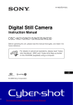
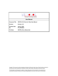
Citect for Windows
Driver Specification Extract
Trio Driver
Author:
Date:
Modified:
Date:
Philip Wong
16/6/95
David Rossini
17/02/98
Driver Design Specification
Contents
1.
TARGET DEVICE ......................................................................................................................................4
1.1
INTRODUCTION ......................................................................................................................................4
1.2
DEVICE MANUFACTURER ........................................................................................................................4
1.3
DEVICE DEFINITION ................................................................................................................................4
1.4
COMMUNICATIONS METHOD ....................................................................................................................4
1.4.1
Physical Layer (Layer 1) ...............................................................................................................4
1.4.2
Data Link Layer (Layer 2) .............................................................................................................4
1.4.3
Radio Link Layer (Layer 3)............................................................................................................5
1.4.4
Frame Handling For Transmitting Data. ........................................................................................7
1.4.5 Frame Handling For Receiving data...................................................................................................7
1.5
COMMUNICATIONS/HARDWARE CONFIGURATION .......................................................................................8
1.5.1
Wiring Diagrams...........................................................................................................................8
1.5.2
I/O Device Settings.......................................................................................................................8
1.5.3
Software Setup.............................................................................................................................8
1.6
SPECIAL REQUIREMENTS ........................................................................................................................9
1.7
MAXIMUM REQUEST LENGTH...................................................................................................................9
3.
USER INTERFACE..................................................................................................................................10
3.1
INTRODUCTION ....................................................................................................................................10
3.2
DRIVER NAME .....................................................................................................................................10
3.3
BOARDS FORM ....................................................................................................................................10
3.3.1
Real Board .................................................................................................................................10
3.3.2
TRIO Board................................................................................................................................10
3.4
PORTS FORM ......................................................................................................................................11
3.4.1
Real Port ....................................................................................................................................11
3.4.1.1 Port Name..................................................................................................................................11
3.4.1.2 Port Number...............................................................................................................................11
3.4.1.3 Board Name ...............................................................................................................................11
3.4.1.4 Baud Rate ..................................................................................................................................11
3.4.1.5 Data Bits ....................................................................................................................................11
3.4.1.6 Stop Bits ....................................................................................................................................11
3.4.1.7 Parity..........................................................................................................................................11
3.4.1.8 Special Opt ................................................................................................................................11
3.4.2
TRIO Port...................................................................................................................................12
3.4.2.1 Port Name..................................................................................................................................12
3.4.2.2 Port Number...............................................................................................................................12
3.4.2.3 Board Name ...............................................................................................................................12
3.4.2.4 Baud Rate ..................................................................................................................................12
3.4.2.5 Data Bits ....................................................................................................................................12
3.4.2.6 Stop Bits ....................................................................................................................................12
3.4.2.7 Parity..........................................................................................................................................12
3.4.2.8 Special Opt ................................................................................................................................12
3.5
I/O DEVICE FORM................................................................................................................................12
3.5.1
Name .........................................................................................................................................12
3.5.2
Number ......................................................................................................................................12
3.5.3
Address......................................................................................................................................12
3.5.4
Protocol......................................................................................................................................13
3.5.5
Port Name..................................................................................................................................13
3.6
PULLDOWN LISTS HELP ........................................................................................................................14
3.7
PARAMETERS AND INI OPTIONS.............................................................................................................14
3.7.1
Standard Parameters .................................................................................................................14
3.7.2
Driver Specific Parameters .........................................................................................................14
3.8
HINTS AND TIPS...................................................................................................................................14
2
TRIO Radio
(15/12/97)
Driver Design Specification
4.
REFERENCES.........................................................................................................................................15
4.1 REFERENCES ...........................................................................................................................................15
3
TRIO Radio
(15/12/97)
Driver Design Specification
1.
1.1
Target Device
Introduction
This section defines the types of I/O Devices that are targeted by this driver.
1.2
Device Manufacturer
TRIO Communications 2000 Pty Ltd
41 Aster Ave Carrum Downs Vic 3201
Telephone: 61 3 9775 0505, Fax: 61 3 9775 0606
1.3
Device Definition
TC-900DR 900MHz Full Duplex Transceiver (Radio Modem)
1.4
Communications Method
ISO-OSI
Layer
5-7
4
3
2
1
1.4.1
Name
Implementation
Application
Serial Driver
Radio Link
Data Link
Physical
Citect
Citect Serial Protocols
TRIO Driver
COMX
RS232
Physical Layer (Layer 1)
RS232
1.4.2
Data Link Layer (Layer 2)
COMX driver.
4
TRIO Radio
(15/12/97)
Driver Design Specification
1.4.3
Radio Link Layer (Layer 3)
Point to Point modem connection
1
1
One to Many modem connection
1,2,3
1,2,3
1
1,2,3
2,3
2,3
2,3
2
2,3
"Repeater" modem connection
3
5
TRIO Radio
(15/12/97)
Driver Design Specification
To understand the functionality required of this driver, it is helpful to first understand the
functionality of the radio modems that the driver utilises.
The modems carry data in frames (packets), and are required to route these frames between
points - the routing may be in a simple one-to-one relationship, a one-to-many relationship or a
complex network.
As there could be many radio modems sharing the same frequency, all modems would receive
all messages transmitted, and hence an addressing mechansim is required to ensure the routing
integrity of the communication streams. This is achieved by marking the first byte of each frame
as a Stream Identifier (SID) code.
1.4.3.1 Radio Modem Functionality
A modem has two ports and a diagnostics utility, each of these have parameters to store two
SID code values. A modem port can be set to operate in one of two modes.
1.4.3.2 User Mode
When the modem port is routing messages on a simple point-to-point basis, it would be set to
operate in the “USER” mode. In this mode, the port will receive frames matching its first SID
code parameter (the Rx SID code). The SID code byte will be removed from the frame, and the
message will then be passed on to its attached device (such as a PLC). Messages from the
device will be broken into one or more frames for transmission, with the ports second SID code
parameter (The Tx SID code) inserted at the start of each frame, prior to transmission. The
modem port on the opposite end would also be set in the “USER” mode, with the Tx SID code
parameter of one modem matching the Rx SID code parameter of the other, and vice-versa.
1.4.3.3 Trunk Mode
When the modem port is routing messages on a “repeater” basis to other selected modems, it
would be set to operate in the “TRUNK” mode. In this mode, the port will receive frames which
have a SID code that lies within the ports first SID code parameter (the Low SID code) and the
ports second SID code parameter (the High SID code) inclusive. The SID code will not be
removed from the frame, and hence the message will be passed on un-altered to its attached
device (in this example, another radio modem acting as the “repeater”). Messages from the
device are expected to be in a format ready for transmission (including the SID code), so no
processing is required for transmission. In order to maintain integrity of messages with SID
codes attached, a defined message framing sequence, such as SLIP (Serial Line Interface
Protocol) encapsulation, is recommended. SLIP is a data transport protocol used in serial
interface applications, the Diagnostics Controller Interface Manual listed in Section 4.1
describes the SLIP protocol.
1.4.3.4 Diagnostic Utility
A modems diagnostic utility will receive frames that match the modems Rx SID code for the
diagnostic port. When a match is found, the diagnostic utility then compares the serial number
of the modem against the serial number of the received diagnostic message. If the serial
numbers match, then the diagnostic utility will reply, with the SID code of the reply frames set to
the diagnostic utilities Tx SID code.
The Radio Link Layer sits between CITECT’s low level serial driver (COMX) and the Citect
serial protocol drivers. It allows the protocol driver to select which radio in the field it wants to
talk to. The protocol driver does not have to be recoded in order to use this layer, they need
only be re-linked.
The modem on the CITECT end must be in SLIP mode, live Frame mode disabled, using
TRUNK mode (with the Low and High SID code parameters set to their outer limits). If there are
multiple slave modems, or if the protocol being used is full duplex, the PTT (Press To Talk)
should be permanently activated with RTS; the Diagnostics Controller Interface Manual, listed
in Section 4.1, describes these matters in further detail.
The routing functionality of this modem is effectively made obsolete by this driver. As discussed
above, the modem will relay, in TRUNK mode, all frames that it receives from either direction.
6
TRIO Radio
(15/12/97)
Driver Design Specification
This driver allows the user to configure “virtual” ports for use by protocol drivers, with each
“virtual” port providing the equivalent routing functionality of a radio modem. The user
configures two SID code parameters per “virtual” port, the Rx and Tx SID codes, in the ports
form..
This driver will send all communications from the “virtual” ports, to one physical comms port.
This port is attached to the local radio modem, which then transmits the frames, to be received
by the appropriate remote radio modem. All frames received by the local radio modem, from
the remote radio modems, are in turn received by this driver through the physical port. The
driver will then route the communications to the appropriate “virtual” port.
The modem on the PLC end should be configured according to the Trio Interface Bulletins. A
bulletin defining User Port Setup details is available for most PLC and RTU brands.
1.4.4
Frame Handling For Transmitting Data.
Each buffer (message) to be transmitted can either be transmitted as one frame, or split into
smaller frames (of a nominal size of 16 bytes), with each individual frame encapsulated in a
SLIP envelope. The first byte inside the SLIP envelope is assigned the value of the Tx SID code
parameter for that “virtual” port. Each frame is then sent to the radio modem via the physical
port. Smaller frames are used to reduce the transmit delay, as the radio will only transmit when
it receives an entire SLIP frame, however some protocols will not tolerate this message
distortion and require the “virtual” port to enforce one frame per message. (See Trio interface
notes for further information on message framing).
1.4.5 Frame Handling For Receiving data.
When a frame is received with a SID code that matches the Rx SID code parameter of a
“virtual” port, the SLIP frame and SID code will be removed from the frame, and the data
passed to that “virtual” port.
7
TRIO Radio
(15/12/97)
Driver Design Specification
1.5
Communications/Hardware Configuration
1.5.1
Wiring Diagrams
Male DB9
Female DB9
COM
5
5
9
DTR
4
4
RTS
8
8
TXD
3
3
CTS
RTS
7
RXD
2
6
7
DSR
7
2
6
1
1
RADIO port A
CITECT port
1.5.2
9
I/O Device Settings
N/A
1.5.3
Software Setup
As discussed in section1.4.3, the radio modems must be configured to match the actual network
application. The configuration of the remote radio modems should be configured on an application
basis as advised by Trio Interface Bulletins. A typical configuration for the local (base) radio modem
follows.
1.5.3.4 Typical TC-900DR configuration for local radio modem
User Port A Parameters
Async Baud Rate
9600 bps
Data Bits
8
Parity
None
Stop Bits
1
Flow Control
H/W Handshaking
Yes
Packet Assembler/Disassembler (PAD) Setup
SLIP mode
Yes
Live Frame mode
No
CTS Dependency
8
TRIO Radio
(15/12/97)
Driver Design Specification
CTS Inactive if RTS Inactive
Port B
Yes
Enable Port B
No
Radio Parameters
Tx Power
Rx Carrier Min RSSI Level
PTT Time-Out
PTT Time-Out
Min Tx Power
Min Tx Alarm Level
Drift Offset
Drift Offset
-105 dBm
Off
100 mW
0 (default)
System Parameters
Lead In Delay
Lead In Delay
SID codes
Enable SID codes
Port A
Mux/Demux or Stream Routing
60 mS
Yes
Stream Routing (M/D = USER mode, S/R = TRUNK
mode)
0
255
SID A1 Code (Low SID code)
SID A2 Code (High SID code)
Diagnostics
SID D1 Code (Low SID code)
0 (Depends on network configuration, refer to Section 3.8)
SID D2 Code (High SID code)
0 (Depends on network configuration, refer to Section 3.8)
PTT Activation
Activate PTT with RTS signal
Yes
System Functions
Collision Avoidance
Yes
Master or Remote
Master
Supervisory Functions
Tx Channel Rate
1
Rx Channel Rate
0
Min RSSI Collision Avoidance Mode
Min RSSI Collision Avoidance
No
Mode
MODEM OPTIONS & REPEATER SETTINGS
Port A – Enable/Disable Repeater
Disable
1.6
Special Requirements
Configuration of the radio modem parameters will require the use of a TC-DFM91P programmer.
1.7
Maximum Request Length
N/A
9
TRIO Radio
(15/12/97)
Driver Design Specification
3.
3.1
User Interface
Introduction
This section defines how the user will see the driver. This relates directly to how the Citect forms need
to be filled out and any special INI options.
3.2
Driver Name
TRIO
3.3
Boards Form
Boards forms must be completed for both a real board and a TRIO board.
3.3.1
Real Board
The real board provides the physical data path for CITECT to communicate with a TRIO radio modem.
(The settings below are for using the computers COM port).
3.3.1.1 Board Name
User supplied unique name for board.
3.3.1.2 Board Type
COMX
3.3.1.3 Address
0
3.3.1.4 IO Port
NA
3.3.1.5 Interrupt
NA
3.3.1.6 Special Opt
N/A
3.3.2
TRIO Board
The TRIO board acts conceptually as a physical board, and provides the framework on which TRIO
“virtual” ports are implemented. All data to/from the TRIO board has a physical path to the radio
modem through the real port specified in the Special Options field.
TRIO boards must be defined after all real serial boards.
Up to 8 TRIO boards may be defined.
3.3.2.1 Board Name
User supplied unique name for board.
10
TRIO Radio
(15/12/97)
Driver Design Specification
3.3.2.2 Board Type
TRIO
3.3.2.3 Address
0
3.3.2.4 IO Port
NA
3.3.2.5 Interrupt
NA
3.3.2.6 Special Opt
PortName of real serial port (attached to radio modem).
3.4
Ports Form
Ports forms must be completed for a real port and also a TRIO “virtual” port for each unique Rx SID
code in the radio modem network.
3.4.1
Real Port
The port used to physically connect to a radio modem.
3.4.1.1 Port Name
User supplied unique name for real port.
3.4.1.2 Port Number
Port number for real port
(COM port number if using computers COM port)
3.4.1.3 Board Name
Name of real board.
3.4.1.4 Baud Rate
9600
3.4.1.5 Data Bits
8
3.4.1.6 Stop Bits
1
3.4.1.7 Parity
none
3.4.1.8 Special Opt
none
11
TRIO Radio
(15/12/97)
Driver Design Specification
3.4.2
TRIO Port
A “virtual” port is to be configured for each protocol driver requiring communication over the radio
modem. This includes the TRIO diagnostics driver.
Up to 100 “virtual” ports may be defined for the system.
3.4.2.1 Port Name
User supplied unique name for “virtual” TRIO port.
3.4.2.2 Port Number
Tx SID code (0 to 255)
3.4.2.3 Board Name
A TRIO board defined in Boards form.
3.4.2.4 Baud Rate
NA
3.4.2.5 Data Bits
NA
3.4.2.6 Stop Bits
NA
3.4.2.7 Parity
NA
3.4.2.8 Special Opt
The first five characters should be of the format “*Unnn” .
“nnn” is the Rx SID code parameter (0 to 255)
If using a protocol that doesn’t support its messages being fragmented into separate frames, such as
modbus, include the “*M” flag as the seventh and eight characters. This will force the frame size to be
that of the protocols message. Note that most protocols will NOT require this flag.
Any special options required for the protocol driver should be included after these flags.
3.5
I/O Device Form
3.5.1
Name
User supplied, unique for I/O device
3.5.2
Number
Network wide I/O device number
3.5.3
Address
Depends on protocol
12
TRIO Radio
(15/12/97)
Driver Design Specification
3.5.4
Protocol
Protocol name
3.5.5
Port Name
Refer to "Port Name" in TRIO Ports form
13
TRIO Radio
(15/12/97)
Driver Design Specification
3.6
Pulldown lists Help
The following entries should be included in the Citect HELP.DBF spec file.
TYPE
DATA
BOARD
TRIO
3.7
Parameters and INI options
3.7.1
Standard Parameters
FILTER
N/A
3.7.2
Driver Specific Parameters
[TRIO]
FrameSize = 16 bytes. (Maximum frame size is 256 bytes.)
If the “*M” flag has not been set in the Special Opt field of a port, then messages will be broken
into frames of size FrameSize prior to transmission.
3.8
Hints and Tips
The radio modem network should be set up such that all modems with a particular diagnostic Rx SID
code also share a particular diagnosticTx SID code. For instance, a network may be constructed with
SID codes 10 and 110 reserved for use as diagnostic Rx and T SID codes for a particular group of
modems in the network. This grouping is required as the TRIO diagnostics driver will require a “virtual”
port configured for each diagnostic group, and hence will require all valid diagnostic replies for a
particular Rx SID code be transmitted to a corresponding Tx SID code.
14
TRIO Radio
(15/12/97)
Driver Design Specification
4.
References
4.1 References
TC-900DR 900Mhz Full Duplex Data Transceiver
User Manual. Issue 5
Programming Operators Guide. Issue 2.A : October 1994
Diagnostics Controller User Manual. Issue 3: September 1994
Application Note AN-D13 “External Stream Router Applications for the TC-900DR”: March 1997
15
TRIO Radio
(15/12/97)