1
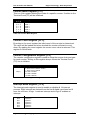
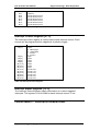
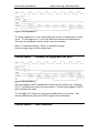
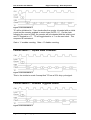
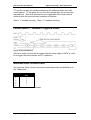
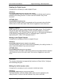
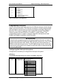
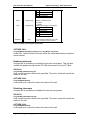
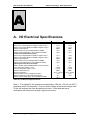
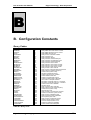
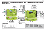
PCI 14 Series
PCI PnP Digital I/O Board
User’s Manual
Revision 1.3
Eagle Technology – Cape Town, South Africa
Copyright © 2001
PCI 14 Series User Manual
Eagle Technology - Data Acquisition
Digital I/O Boards
Data Acquisition and Process Control
© Eagle Technology
31-35 Hout Street • Cape Town • South Africa
Eagle Technology © Copyright 2001
i
PCI 14 Series User Manual
Eagle Technology - Data Acquisition
Copyright
All rights reserved. No part of this publication may be reproduced, stored in a
retrieval system, or transmitted, in any form or any means, electronic,
mechanical, by photographing, recording, or otherwise without prior written
permission.
Copyright © Eagle Technology, South Africa
August 2001
Revision 1.3
Information furnished in this manual is believed to be accurate and reliable;
however no responsibility is assumed for its use, or any infringements of
patents or other rights of third parties, which may result from its use.
Trademarks and Logos in this manual are the property of their respective
owners.
Product Warranty
Eagle Technology, South Africa, warrants its products from defect in material
and workmanship from confirmed date of purchase for a period of one year if
the conditions listed below are met. The product warranty will call the Eagle
Technology Data Acquisition Device short as ETDAQD.
•
•
•
The warranty does not apply to an ETDAQD that has been previously
repaired, altered, extended by any other company or individual outside the
premises of Eagle Technology.
That a qualified person configure and install the ETDAQD, and damages
caused to a device during installation shall make the warranty void and
null.
The warranty will not apply to conditions where the ETDAQD has been
operated in a manner exceeding its specifications.
Eagle Technology, South Africa, does not take responsibility or liability of
consequential damages, project delays, damaging of equipment or capital
loss as a result of its products.
Eagle Technology, South Africa, holds the option and final decision to repair
or replace any ETDAQD. Proof of purchase must be supplied when
requesting a repair.
Eagle Technology © Copyright 2001
ii
PCI 14 Series User Manual
Eagle Technology - Data Acquisition
TABLE OF CONTENTS
1.
INTRODUCTION
1
Features
1
Applications
2
Key Specifications
2
Software Support
2
Contact Details
2
2.
3
INSTALLATION
Package
3
Hardware Installation
3
Software Installation
Windows 98/2000/ME
Post installation
Windows NT
Testing your board
4
4
7
8
9
Accessories
9
3.
INTERCONNECTIONS
10
External Connectors
10
Pin Assignments
10
Signal Definitions
11
Digital Inputs
11
Digital Outputs
11
Counters
12
4.
13
FUNCTIONAL OVERVIEW
Device Address Map
13
Counter Mode Register [2..0]
14
Counter Count Register [23..0]
14
Eagle Technology © Copyright 2001
iii
PCI 14 Series User Manual
Eagle Technology - Data Acquisition
Counter Configuration Register [2..0]
14
Interrupt Mask Register [13..0]
14
Interrupt Control Register [27..0]
15
Interrupt Status Register [13..0]
15
Counter Mode 0 – Interrupt on terminal count.
15
Counter Mode 1 – Hardware re-triggerable one shot.
16
Counter Mode 2 – Rate Generator.
16
Counter Mode 3 – Square Wave Generator.
17
Counter Mode 4 – Software Triggered Strobe.
17
Counter Mode 5 – Hardware Triggered Strobe
18
Minimum Initial Counter Limits
18
5.
19
PROGRAMMING GUIDE
EDR Enhanced API
19
Examples
19
Digital Inputs
Reading the Digital Inputs
19
20
Digital Outputs
Writing to the Digital Outputs
20
20
Counters
Writing the initial counter value
Reading a Counter
Configuring a counter
Controlling the counter gate
Configuration Constants
20
20
21
21
21
22
Multi Function I/O
Configuring the outputs
22
22
Programming Interrupts
Configuring the Interrupt sub-system
Enabling Interrupts
Disabling Interrupts
Programming interrupts by using the EDREIntX OCX
Visual Basic Interrupt Example
23
23
24
24
25
25
A.
26
I/O ELECTRICAL SPECIFICATIONS
Eagle Technology © Copyright 2001
iv
PCI 14 Series User Manual
B.
Eagle Technology - Data Acquisition
CONFIGURATION CONSTANTS
27
Query Codes
27
Error Codes
28
Digital I/O Codes
28
C.
29
ORDERING INFORMATION
Eagle Technology © Copyright 2001
v
PCI 14 Series User Manual
Eagle Technology - Data Acquisition
Table of Figures
Figure 2-1 Add New Hardware Wizard Step1 ................................................. 4
Figure 2-2 Add New Hardware Wizard Step2 ................................................. 5
Figure 2-3 Add New Hardware Wizard Step3 ................................................. 5
Figure 2-4 Add New Hardware Wizard Step4 ................................................. 6
Figure 2-5 Add New Hardware Wizard Step5 ................................................. 6
Figure 2-6 Restart Your Computer .................................................................. 7
Figure 2-7 System Properties.......................................................................... 7
Figure 2-8 EagleDAQ ...................................................................................... 8
Figure 4-1 Counter Mode 0 ........................................................................... 16
Figure 4-2 Counter Mode 1 ........................................................................... 16
Figure 4-3 Counter Mode 2 ........................................................................... 17
Figure 4-4 Counter Mode 3 ........................................................................... 17
Figure 4-5 Counter Mode 4 ........................................................................... 17
Figure 4-6 Counter Mode 5 ........................................................................... 18
Eagle Technology © Copyright 2001
vi
PCI 14 Series User Manual
Eagle Technology - Data Acquisition
Table of Tables
Table 1-1 PCI14 Versions ............................................................................... 1
Table 3-1 External Connector – SCSI 68F CENT ......................................... 11
Table 3-2 Input ports ..................................................................................... 11
Table 3-3 Output ports .................................................................................. 11
Table 4-1 Device Address Map ..................................................................... 13
Table 4-2 Counter Mode Register ................................................................. 14
Table 4-3 Counter Configuration Register..................................................... 14
Table 4-4 Interrupt Mask Register ................................................................. 15
Table 4-5 Interrupt Control Register .............................................................. 15
Table 4-6 Mode and initial count limits .......................................................... 18
Table 5-1 Clock Configuration....................................................................... 22
Table 5-2 Gate Configuration ........................................................................ 22
Table 5-3 Multiple I/O Configuration.............................................................. 23
Table 5-4 EDRE_IntConfigure Parameters ................................................... 24
Table A-1 I/O Electrical Specifications .......................................................... 26
Table B-1 Query Code .................................................................................. 27
Table B-2 Error Codes .................................................................................. 28
Table B-3 Digital I/O Codes........................................................................... 28
Table C-1 Ordering Information..................................................................... 29
Eagle Technology © Copyright 2001
vii
PCI 14 Series User Manual
Eagle Technology - Data Acquisition
1
1. Introduction
The PCI14 series are 32-bit PCI bus architecture data acquisition boards.
They are available in two basic models, the B and C. The PCI14 contains
digital input and output ports and onboard counters. The PCI14 is a multipurpose digital board that can be used in many applications. It also contains
features for digital input and output protection. The counter modes are
compatible with the Intel 8254.
Features
The PCI14 does have some very unique features and are short listed below:
•
•
•
•
•
•
•
•
•
•
32-bit PCI bus Revision 2.2 compliant at 33MHz.
PCI Bus 3.3V compatible.
6 counters for B version and 2 for C version.
Counter modes are compatible with Intel 8254.
Fully configurable counter sub-system; includes internal clock source
(40MHz) or external, internal or external gates.
24 x digital input lines and 24 x digital output lines.
50 mA sink, 20 mA source digital outputs with short circuit protection. High
impedance on power up or loss.
Overvoltage protection on all digital inputs.
Overvoltage protection on digital outputs (B version only).
Fully programmable interrupt system: interrupts generated from counters
or 8 x digital inputs.
Feature
Number of digital input channels
Number of digital output channels
Number of 24-bit counters
High voltage digital input protection
High voltage digital output protection
PCI14B
24
24
6
Yes
Yes
PCI14C
24
24
2
Yes
No
Table 1-1 PCI14 Versions
Eagle Technology © Copyright 2001
1
PCI 14 Series User Manual
Eagle Technology - Data Acquisition
Applications
The PCI14 can be used in the following applications:
• Digital control applications.
• Digital monitoring applications.
• Frequency measurement.
• Pulse generation.
• Timing applications.
• Pulse counting.
Key Specifications
•
•
•
24-bit digital input port.
24-bit digital output port.
24-bit counters.
Software Support
The PCI14 is supported by EDR Enhanced and comes with an extensive
range of examples. The software will help you to get your hardware going very
quickly. It also makes it easy to develop complicated control applications
quickly. All operating system drivers, utility and test software are supplied on
the EDR Enhanced CD-Rom. The latest drivers can also be downloaded from
the Eagle Technology website. For further support information see the
Contact Details section.
Contact Details
Eagle Technology © Copyright 2001
2
PCI 14 Series User Manual
Eagle Technology - Data Acquisition
2
2. Installation
This chapter describes how to install and configure the PCI14 for the first time.
Minimal configuration is necessary; almost all settings are done through
software. The PCI BIOS or operating system will take care of all resource
assignments.
Package
PCI14 package will contain the following:
• PCI14 PCI board
• EDR Enhanced Software Development Kit CD-Rom
Hardware Installation
This section will describe how to install your PCI14 into your computer.
•
Switch off the computer and disconnect from power socket.
Failure to disconnect all power cables
can result in hazardous conditions, as
there may be dangerous voltage levels
present in externally connected
cables.
•
•
•
•
•
•
Remove the cover of the PC.
Choose any open PCI slot and insert PCI14 board
Insert bracket screw and ensure that the board sits firmly in the PCI
socket.
Replace the cover of the PC.
Reconnect all power cables and switch the power on.
The hardware installation is now completed.
Eagle Technology © Copyright 2001
3
PCI 14 Series User Manual
Eagle Technology - Data Acquisition
Software Installation
Windows 98/2000/ME
Installing the Windows 98/2000 device driver is a very straightforward task.
Because it is plug and play Windows will auto detect the PCI14 as soon as it
is installed. No setup is necessary. You simply have to supply Windows with a
device driver.
Wait until Windows detects the new hardware
Figure 2-1 Add New Hardware Wizard Step1
Select Next
Eagle Technology © Copyright 2001
4
PCI 14 Series User Manual
Eagle Technology - Data Acquisition
Figure 2-2 Add New Hardware Wizard Step2
Select default option, search for best driver and select next
Figure 2-3 Add New Hardware Wizard Step3
Select specify a location and enter the directory location of the driver
on the Eagle CD Rom. The driver should be located in the
<CDROM>:\EDRE\Drivers\WDM\PCI14B directory.
Select Next to proceed
Eagle Technology © Copyright 2001
5
PCI 14 Series User Manual
Eagle Technology - Data Acquisition
Figure 2-4 Add New Hardware Wizard Step4
Windows should have detected the proper driver and ready to install
it. Select Next to proceed.
Figure 2-5 Add New Hardware Wizard Step5
Click on the finish button to complete the installation.
Click Yes to restart your computer.
Eagle Technology © Copyright 2001
6
PCI 14 Series User Manual
Eagle Technology - Data Acquisition
Figure 2-6 Restart Your Computer
Post installation
After your installation was complete there is a few steps that can be followed
to check that your installation was successful.
•
•
First make sure that the driver is working properly by opening the
system folder in the control panel.
Check under the Eagle Data Acquisition list if your board is listed and
working properly. See picture below.
Figure 2-7 System Properties
•
Clearly you can see that the PCI14 is listed and working properly.
Eagle Technology © Copyright 2001
7
PCI 14 Series User Manual
•
Eagle Technology - Data Acquisition
Further open the control panel and then the EagleDAQ folder. This
dialog should list all installed hardware. Verify your board’s properties
on this dialog. See picture below
Figure 2-8 EagleDAQ
Now the first part of your installation has been completed and ready to
install the EDR Enhanced Software Development Kit.
•
Run setup.exe found on the EDR Enhanced SDK CD-Rom and follow
the on screen instructions
Windows NT
Windows NT does not require any special setup procedure. The Windows NT
driver does not support plug and play. If Windows 2000 detects a new device
simply install a default driver, or so called placeholder.
To install the Windows NT drivers simply run EDREWinnt.exe on the Eagle
CD-Rom. This will automatically install the device drivers. Restart your
computer when done. Open the EagleDAQ folder in the control panel to check
if your installation was successful. Figure 2-8 shows a successful installation.
Eagle Technology © Copyright 2001
8
PCI 14 Series User Manual
Eagle Technology - Data Acquisition
Testing your board
To test your board, run the application supplied on the Eagle CD-Rom. Install
the following program <EAGLECD>:\EDRE\APPS\PCI14B\pci14b.exe. Run it
to test all features on your board.
Accessories
The PCI14 does have a wide variety of accessories that it can be connected
too. See the Eagle Technology catalog for more information.
Eagle Technology © Copyright 2001
9
PCI 14 Series User Manual
Eagle Technology - Data Acquisition
3
3. Interconnections
The PCI14 has got one external connector that includes both digital I/O and
counter signals. All connections are made through this connector situated on
the card’s bracket.
External Connectors
The PCI14 has a SCSI female centronics 68-way connector. As part of the
accessories a cable and adapter can be ordered.
Pin Assignments
The table below shows the pin assignments for the PCI14.
Pin
1
2
3
4
5
6
7
8
9
10
11
12
13
14
15
16
17
18
19
20
21
22
Name
+5V
DI2
DI4
DI6
DI8
DI10
DI12
Di14
DI16
DI18
DI20
DI22
DI24
DGND
CNTR0_CLK
CNTR1_CLK
CNTR2_CLK
CNTR3_CLK
CNTR4_CLK
CNTR5_CLK
DGND
DO1/CNTR0_TC
Pin
35
36
37
38
39
40
41
42
43
44
45
46
47
48
49
50
51
52
53
54
55
56
Name
+5V
DI1
DI3
DI5
DI7
DI9
DI11
DI13
DI15
DI17
DI19
DI21
DI23
DGND
CNTR0_GATE
CNTR1_GATE
CNTR2_GATE
CNTR3_GATE
CNTR4_GATE
CNTR5_GATE
DGND
DO2/CNTR1_TC
Eagle Technology © Copyright 2001
10
PCI 14 Series User Manual
23
24
25
26
27
28
29
30
31
32
33
34
DO3/CNTR2_TC
DO5/CNTR4_TC
DO7
DO9
DO11
DO13
DO15
DO17
DO19
DO21
DO23
DGND
57
58
59
60
61
62
63
64
65
66
67
68
Eagle Technology - Data Acquisition
DO4/CNTR3_TC
DO6/CNTR5_TC
DO8
DO10
DO12
DO14
DO16
DO18
DO20
DO22
DO24
DGND
Table 3-1 External Connector – SCSI 68F CENT
Signal Definitions
This sections deal with all the signals abbreviations.
Signal
DI1-24
DO1-24
CNTRx_CLK
CNTRx_GATE
+5V
DGND
Description
Digital Inputs
Digital outputs
External clock lines
External gate lines
+5V power supply line
Digital ground
Table 3-2 Signal definitions
Digital Inputs
The PCI14 has got 24 digital input lines. See specification for input protection.
Please note when programming the PCI14 the 24 lines are split into 3 ports of
8-bits. This is to be compatible with the ISA PC14B.
Port
0
1
2
Lines
1-8
9-16
17-24
Table 3-2 Input ports
Digital Outputs
The PCI14 has got 24 digital output lines. See specification for output
protection. Please note when programming the PCI14 the 24 lines are split
into 3 port of 8-bits. This is to be compatible with the ISA PC14B. The outputs
can also be configured to be high impedance. Lines 1-6 are the same as the 6
terminal count lines of the counters and must be configured for either.
Port
0
1
2
Lines
1-8
9-16
17-24
Table 3-3 Output ports
Eagle Technology © Copyright 2001
11
PCI 14 Series User Manual
Eagle Technology - Data Acquisition
Counters
There are 6 counter or 2 counters on the PCI14 depending on the version.
The counter modes are fully compatible with the Intel 8254 and can be
programmed for internal clock or gate or external clock or gate or a
combination of clock and gates. All external clock and gate lines are accessed
via the external connector. The terminal count lines are shared with the first 6
digital output lines and have to be configured for either. It has an internal clock
of 40MHz.
Eagle Technology © Copyright 2001
12
PCI 14 Series User Manual
Eagle Technology - Data Acquisition
4
4. Functional Overview
This section provides a functional overview of the PCI14B board.
Device Address Map
The table below defines the address map as per offset of base address 0.
Offset
Address
(HEX)
000
004
008
010
014
018
020
024
028
030
034
038
040
044
048
050
054
058
080
084
088
08C
090
0A0
0B0
Register Name
Description
CNT0_MODE
CNT0_COUNT
CNT0_CONFIG
CNT1_MODE
CNT1_COUNT
CNT1_CONFIG
CNT2_MODE
CNT2_COUNT
CNT2_CONFIG
CNT3_MODE
CNT3_COUNT
CNT3_CONFIG
CNT4_MODE
CNT4_COUNT
CNT4_CONFIG
CNT5_MODE
CNT5_COUNT
CNT5_CONFIG
INT_MASK
INT_CONTROL
INT_STATUS
OUTPUT_CNTRL
OUTPUT_REG
INPUT_REG
EEPROM_REG
Mode Register
Initial count / Current count
Configuration
Mode Register
Initial count / Current count
Configuration
Mode Register
Initial count / Current count
Configuration
Mode Register
Initial count / Current count
Configuration
Mode Register
Initial count / Current count
Configuration
Mode Register
Initial count / Current count
Configuration
Interrupt mask
Interrupt control
Interrupt status / Reset
Setup output sources
Setting output lines
Reading input lines
EEPROM Interface
Read/Write
W
W/R
W
W
W/R
W
W
W/R
W
W
W/R
W
W
W/R
W
W
W/R
W
W
W
W/R
W
W
R
W/R
Table 4-1 Device Address Map
Eagle Technology © Copyright 2001
13
PCI 14 Series User Manual
Eagle Technology - Data Acquisition
Counter Mode Register [2..0]
This is a 3-bit register defining the mode of a specific counter. If written to the
Terminal Count(TC) will be initialized.
Bits[0..2]
[2 | 1 | 0]
[0 : 0 : 0]
[0 : 0 : 1]
[0 : 1 : 0]
[0 : 1 : 1]
[1 : 0 : 0]
[1 : 0 : 1]
Description
Mode 0
Mode 1
Mode 2
Mode 3
Mode 4
Mode 5
Table 4-2 Counter Mode Register
Counter Count Register [23..0]
By writing to the count register the initial count of the counter is determined.
The value will be loaded and when clocked the counter will start to count
down. By reading the count register the current count value is returned. This
register is 24-bits wide.
Counter Configuration Register [2..0]
The counter configuration register is used to setup the source clock and gate
for each counter. Writing to this register always forces the Terminal Count
(TC) line to initialize.
Bit[0..2]
Bit 0
Bit [2:1]
Description
Specifies the Clock Source
0 : Clock source is internal – 40 MHz
1 : Clock source is external
00 : Gate is disabled
01 : Gate is enabled
10 : Gate is external
Table 4-3 Counter Configuration Register
Interrupt Mask Register [13..0]
The interrupt mask register is used to enable or disable all 14 interrupt
sources. Eight interrupt are derived from the first 8 digital input lines and 6
from the counters. A logic 1 mask an interrupt and a logic 0 enables an
interrupt.
Bits [0..13]
Bit 0
Bit 1
Bit 2
Bit 3
Bit 4
Bit 5
Description
Input line 0
Input line 1
Input line 2
Input line 3
Input line 4
Input line 5
Eagle Technology © Copyright 2001
14
PCI 14 Series User Manual
Bit 6
Bit 7
Bit 8
Bit 9
Bit 10
Bit 11
Bit 12
Bit 13
Eagle Technology - Data Acquisition
Input line 6
Input line 7
Counter terminal count 0
Counter terminal count 1
Counter terminal count 2
Counter terminal count 3
Counter terminal count 4
Counter terminal count 5
Table 4-4 Interrupt Mask Register
Interrupt Control Register [27..0]
The interrupt control register is used to setup each interrupt source. Each
source can be programmed for edge/level or polarity trigger.
Bits [0..27]
Bit [1:0]
Bit [3:2]
Bit [5:4]
Bit [7:6]
Bit [9:8]
Bit [11:10]
Bit [13:12]
Bit [15:14]
Bit [17:16]
Bit [19:18]
Bit [21:20]
Bit [23:22]
Bit [25:24]
Bit [27:26]
Description
Input 0:
0 : 0 Rising Edge
0 : 1 Falling Edge
1 : 0 Level ‘1’
0 : 0 Level ‘0’
Input 1
Input 2
Input 3
Input 4
Input 5
Input 6
Input 7
Counter 0 TC
Counter 1 TC
Counter 2 TC
Counter 3 TC
Counter 4 TC
Counter 5 TC
Table 4-5 Interrupt Control Register
Interrupt Status Register [13..0]
The Interrupt Status Register supply information on current triggered
interrupts. The register is 14-bit wide for each interrupt source. If set
Counter Mode 0 – Interrupt on terminal count.
Eagle Technology © Copyright 2001
15
PCI 14 Series User Manual
Eagle Technology - Data Acquisition
Figure 4-1 Counter Mode 0
TC will be initialized to ‘0’ two clocks after the counter is loaded with an initial
count. TC will toggle to a ‘1’ one clock after the counter has reached zero.
This state is maintained until the initial count is re-loaded.
Gate =’1’ enabled counting. Gate = ‘0’ disable counting.
Only the rising edge of Gate is significant.
Counter Mode 1 – Hardware re-triggerable one shot.
Figure 4-2 Counter Mode 1
The rising edge of GATE reloads the counter with the initial count, initializes
TC to ‘1’ and starts the down-count sequence. Further rising edges of GATE
will re-initialize this state.
TC will toggle to ‘0’ whenever the counter reaches the count of two. This
state is maintained until a new GATE trigger event is detected.
Counter Mode 2 – Rate Generator.
Eagle Technology © Copyright 2001
16
PCI 14 Series User Manual
Eagle Technology - Data Acquisition
Figure 4-3 Counter Mode 2
TC will be initialized to ‘1’ two clocks after the counter is loaded with an initial
count and the counter enabled to count down (GATE =’1’). On the clock
following the count of ONE, the counter will be reloaded with the initial count
and TC toggled to a ‘0’. TC will toggle back to a ‘1’ on the next clock. This
sequence is maintained.
Gate = ‘1’ enables counting. Gate = ‘0’ disable counting.
Counter Mode 3 – Square Wave Generator.
Figure 4-4 Counter Mode 3
This is the similar to mode 2 except that TC has a 50% duty cycle signal.
Counter Mode 4 – Software Triggered Strobe.
Figure 4-5 Counter Mode 4
Eagle Technology © Copyright 2001
17
PCI 14 Series User Manual
Eagle Technology - Data Acquisition
TC and the counter are initialized whenever the software writes the initial
count register. TC will pulse low for one clock period after the counter has
reached zero. Note that is sequence is re-triggerable if the initial count is
written before the terminal count condition is reached.
Gate = ‘1’ enables counting. Gate = ‘0’ disables counting.
Counter Mode 5 – Hardware Triggered Strobe
Figure 4-6 Counter Mode 5
Similar to mode four with the exception that the rising edge of GATE is used
to re-trigger the initial counter and TC conditions.
Minimum Initial Counter Limits
The minimum initial counter values are mode dependent and defined as in
the Table below.
Mode
0
1
2
3
4
5
Minimum initial count
value
1
1
2
2
1
1
Table 4-6 Mode and initial count limits
Eagle Technology © Copyright 2001
18
PCI 14 Series User Manual
Eagle Technology - Data Acquisition
5
5. Programming Guide
The PCI14B/C is supplied with a complete software development kit. EDR
Enhanced (EDRE SDK) comes with drivers for many operating systems and a
common application program interface (API). The API also serves as a
hardware abstraction layer (HAL) between the control application and the
hardware. The EDRE API makes it possible to write an application that can be
used on all hardware with common sub-systems.
The PCI14B/C can also be programmed at register level, but it is not
recommended. A detailed knowledge of the PCI14B/C is needed and some
knowledge about programming Plug and Play PCI devices. We recommend
that you only make use of the software provided by Eagle Technology.
EDR Enhanced API
The EDR Enhanced SDK comes with both ActiveX controls and a Windows
DLL API. Examples are provided in many different languages and serve as
tutorials. EDRE is also supplied with a software manual and user’s guide.
The EDRE API hides the complexity of the hardware and makes it really easy
to program the PCI14. It has got functions for each basic sub-system and is
real easy to learn.
Examples
Please refer to the examples directory found in the EDRE folder of the CDRom. There are some complete PCI14B examples.
Digital Inputs
Digital inputs are used to read or monitor devices with a digital output
capability. The PCI14B/C has got 24 inputs and depending on which version
extensive or minimal input protection. The 24 inputs lines are split into 3 x 8bit ports and assigned in the following configuration; lines 0-7 represents port
0, lines 8-15 represents port 1, lines 16-23 represents port 2.
Eagle Technology © Copyright 2001
19
PCI 14 Series User Manual
Eagle Technology - Data Acquisition
Reading the Digital Inputs
A single call is necessary to read a digital I/O port.
API-CALL
Long EDRE_DioRead(ulng Sn, ulng Port, ulng *Value)
The serial number, port, and a pointer to variable to hold the result must be
passed by the calling function. A return code will indicate if any errors
occurred.
ACTIVEX CALL
Long EDREDioX.Read(long Port)
Only the port-number needs to be passed and the returned value will either
hold an error or the value read. If the value is negative an error did occur.
Digital Outputs
Digital outputs are used to control devices with digital inputs. The PCI14B/C
has got 24 inputs and depending on which version extensive or minimal
output protection. The 24 inputs lines are split into 3 x 8-bit ports and assigned
in the following configuration; lines 0-7 represents port 0, lines 8-15
represents port 1, lines 16-23 represents port 2.
Writing to the Digital Outputs
A single call is necessary to write to a digital I/O port.
API-CALL
Long EDRE_DioWrite(ulng Sn, ulng Port, ulng Value)
The serial number, port, and a value must be passed by the calling function. A
return code will indicate if any errors occurred.
ACTIVEX CALL
Long EDREDioX.Write(long Port, ulng Value)
The port number and value to be written needs to be passed and the returned
value holds an error or the value read. If the value is negative an error did
occur.
Counters
The counter sub-system is supported by functions to Read, Write, Configure
and controlling the gate.
Writing the initial counter value
A single call is necessary to write a counter’s initial load value.
API-CALL
Long EDRE_CTWrite(ulng Sn, ulng Ct, ulng Value)
The serial number, counter-number, and a value must be passed by the
calling function. A return code will indicate if any errors occurred.
Eagle Technology © Copyright 2001
20
PCI 14 Series User Manual
Eagle Technology - Data Acquisition
ACTIVEX CALL
Long EDRECTX.Write(long Port, ulng Value)
The port number and value to be written needs to be passed and the returned
value holds an error or the value read. If the value is negative an error did
occur.
Reading a Counter
A single call is necessary to read a counter’s current value.
API-CALL
Long EDRE_CTRead(ulng Sn, ulng Ct, ulng *Value)
The serial number, counter-number, and a pointer to variable to hold the result
must be passed by the calling function. A return code will indicate if any errors
occurred.
ACTIVEX CALL
Long EDRECTX.Read(long Ct)
Only the counter-number needs to be passed and the returned value will
either hold an error or the value read. If the value is negative an error did
occur.
The counter-number and value to be written needs to be passed and the
returned value holds an error or the value read. If the value is negative an
error did occur.
Configuring a counter
A single call is necessary to configure a counter.
API-CALL
Long EDRE_CTConfig(ulng Sn, ulng Ct, ulng Mode, ulng Type, ulng ClkSrc, ulng
GateSrc)
The serial number, counter-number, mode, type (this parameter is ignored),
clock source and gate source is needed to specify a counter’s configuration. A
return code will indicate if any errors occurred.
ACTIVEX CALL
Long EDRECTX.Configure(long ct, long mode, long type, ulng source, ulng gate)
The counter-number, mode, type (this parameter is ignored), clock source and
gate source is needed to specify a counter’s configuration. A return code will
indicate if any errors occurred.
Controlling the counter gate
A single call is necessary to setup/control a counter’s gate
API-CALL
Long EDRE_CTSoftGate(ulng Sn, ulng Ct, ulng Gate)
The serial number, counter-number and gate is needed to control a counter’s
gate. A return code will indicate if any errors occurred.
Eagle Technology © Copyright 2001
21
PCI 14 Series User Manual
Eagle Technology - Data Acquisition
ACTIVEX CALL
Long EDRECTX.SoftGate(ulng Ct, ulng Gate)
The counter-number and mode is needed to control a counter’s gate. A return
code will indicate if any errors occurred.
Configuration Constants
These values are acceptable as a clock source.
Value
0
1
Description
Internal 40Mhz
External
Table 5-1 Clock Configuration
These values are acceptable as a gate source.
Value
0
1
2
Description
Gate disabled
Gate enabled
Gate external
Table 5-2 Gate Configuration
Multi Function I/O
The PCI14 has got some multi I/O lines. These are I/O lines on the connector
that is shared by the counter and digital outputs. The output lines can also be
configured to be high impedance or enabled. The multi I/O configure function
is used to set this up.
Configuring the outputs
A single call is necessary to configure the output lines of the PCI14.
API-CALL
Long EDRE_MioConfig(ulng Sn, ulng Port, ulng Value)
The serial number, Port/Line number, and a value must be passed by the
calling function. A return code will indicate if any errors occurred.
ACTIVEX CALL
Long EDREDioX.MioConfigure(long Port, long Value)
The port-number and value to be written needs to be passed and the returned
value holds an error or the value read. If the value is negative an error did
occur. Please use the table below as reference.
Port
0
1
2
Value
0 : Output 0
1 : Counter 0 TC
0 : Output 1
1 : Counter 1 TC
0 : Output 2
Eagle Technology © Copyright 2001
22
PCI 14 Series User Manual
3
4
5
6
Eagle Technology - Data Acquisition
1 : Counter 2 TC
0 : Output 3
1 : Counter 3 TC
0 : Output 4
1 : Counter 4 TC
0 : Output 5
1 : Counter 6 TC
0 : Outputs are high impedance
1 : Outputs are active
Table 5-3 Multiple I/O Configuration
Programming Interrupts
The PCI14B can generate interrupts from 14 different sources, which include
digital inputs and counters. The interrupt sub-system is totally programmable
and user-space interrupt-service-routines are triggered through events from
the driver. If an event is triggered it also needs to be cleared. The EDRE
interrupt system includes functions to configure, enable, disable. The
configuration function is used to configure a specific interrupt source and
Enable and Disable to globally control interrupts.
WARNING!
Be careful when programming the interrupt sub-system because it is easy to
generate interrupts that is faster than what Windows can service. Don’t try and
generate interrupt faster than 10KHz. This will not work. Remember this is
10KHz in total, and not per source. The PCI14B interrupt service routine will
stop servicing interrupts if at any stage it is still busy with an interrupt and the
next one is generated.
Configuring the Interrupt sub-system
A single call is necessary to configure the interrupt sub-system.
API-CALL
Long EDRE_IntConfigure(ulng Sn, ulng Src, ulng Mode, ulng Type)
Parameter
Sn
Src
Type
Unsigned long
Unsigned long
Description
Board’s Serial Number
Interrupt Source
No Description
0 DIO Line 0
1 DIO Line 1
2 DIO Line 2
3 DIO Line 3
4 DIO Line 4
5 DIO Line 5
6 DIO Line 6
7 DIO Line 7
8 TC Counter 0
9 TC Counter 1
10 TC Counter 2
Eagle Technology © Copyright 2001
23
PCI 14 Series User Manual
Eagle Technology - Data Acquisition
10
11
12
13
Mode
Unsigned long
Type
Unsigned long
RETURN
Long
TC Counter 2
TC Counter 3
TC Counter 4
TC Counter 5
Disable or Enable a source
0 : Disable
1 : Enable
Set the type of trigger for the interrupt
No Description
0 Rising Edge
1 Falling Edge
2 Level = ‘1’
3 Level = ‘0’
This parameter contains the error code
return. If =0 then no error occurred.
Table 5-4 EDRE_IntConfigure Parameters
ACTIVEX CALL
Long EDREIntX.Configure(long Source, long Mode, long Type)
As the DLL call the ActiveX function takes the same parameters except the
serial number.
Enabling Interrupts
A single call is necessary to enable the interrupt sub-system. This will also
enable the global interrupt on the PCI14B and connect it to the PCI Bus.
API-CALL
Long EDRE_IntEnable(ulng Sn)
Only a serial number needs to be specified. The return code will contain the
status of the call.
ACTIVEX-CALL
Long EDREIntX.Enable
A returned error code will contain the status of the call.
Disabling Interrupts
A single call is necessary to disable the interrupt sub-system.
API-CALL
Long EDRE_IntDisable(ulng Sn)
Only a serial number needs to be specified. The return code will contain the
status of the call.
ACTIVEX-CALL
Long EDREIntX.Disable
A returned error code will contain the status of the call.
Eagle Technology © Copyright 2001
24
PCI 14 Series User Manual
Eagle Technology - Data Acquisition
Programming interrupts by using the EDREIntX OCX
The interrupt OCX makes programming interrupts very easy. You only have to
configure the interrupts, Enable/Disable it and implement a trigger. The trigger
will also supply you with the source of the interrupt. By simply clicking on the
control your programming language will jump to the code for you trigger
procedure.
Visual Basic Interrupt Example
Option Explicit
Dim err As Long
Private Sub Command1_Click()
EDREIntX1.Enable
End Sub
Private Sub Command2_Click()
EDREIntX1.Disable
End Sub
Private Sub EDREIntX1_Interrupt(ByVal Source As Long)
'this is the interrupt service routine
End Sub
Private Sub Form_Load()
sn = EDREUtlX1.SelectDialog()
'get a board's serial number
EDREIntX1.SerialNumber = sn
'set the interrupt OCX serial number
err = EDREIntX1.Configure(0, 1, 0)
'configure interrupt system
'source = 0, mode = enable, type = 0
End Sub
Eagle Technology © Copyright 2001
25
PCI 14 Series User Manual
Eagle Technology - Data Acquisition
A
A. I/O Electrical Specifications
SPECIFICATION
Digital Inputs
Minimum input voltage (Relative to DGND) to register a logic ‘1’
Maximum input voltage (Relative to DGND) to register a logic ‘0’
Maximum Input Frequency
Maximum Continuous Input Voltage (Relative to DGND)
Maximum Input Voltage Spike < 100 ms (Relative to DGND)
Counter Clock and Gate Control Inputs
Minimum input voltage (Relative to DGND) to register a logic ‘1’
Maximum input voltage (Relative to DGND) to register a logic ‘0’
Maximum Input Frequency
Maximum Continuous Input Voltage (Relative to DGND)
Maximum Input Voltage Spike < 50 ms (Relative to DGND)
Digital Outputs & Counter Timer Outputs
Number of Digital Outputs (Multiplexed with counter TC outputs.)
Sink current (Output voltage =< 0.5V)
Source current (Output voltage >= 2.5V)
Maximum Output Frequency
Short Circuit protection
Maximum Continuous Over Voltage Stress (Note 1)
Maximum Continuous Under Voltage Stress (Note 1)
Maximum Output Voltage Spike < 50 ms (Relative to DGND)
PCI-14B
PCI-14C
+ 2.5 V
+ 1.0 V
8 MHz
± 32 V
± 80 V
+ 2.5 V
+ 1.0 V
8 MHz
± 32 V
± 80 V
+ 2.5 V
+ 1.0 V
8 MHz
± 32 V
± 80 V
+ 2.5V
+ 1.0 V
8 MHz
± 32 V
± 80 V
24
- 48 mA
+ 18 mA
8 MHz
- 40 to – 140 mA
+ 32 V
- 32 V
± 80 V
24
- 48 mA
+ 18 mA
8 MHz
-40 to –140 mA
+ 5.5 V
- 0.8 V
-
Table A-1 I/O Electrical Specifications
Note 1. For Option B, the outputs are protected by 100 mA ± 20 mA (at 25°C)
polyfuses and 5.6V transorbs. Over or under voltage stress levels longer than
50 ms will activate the fuse protecting the driver. Note also that once
activated such fuses have a fairly long recovery time.
Eagle Technology © Copyright 2001
26
PCI 14 Series User Manual
Eagle Technology - Data Acquisition
B
B. Configuration Constants
Query Codes
Name
APIMAJOR
APIMINOR
APIBUILD
APIOS
APINUMDEV
BRDTYPE
BRDREV
BRDYEAR
BRDMONTH
BRDDAY
BRDSERIALNO
DRVMAJOR
DRVMINOR
DRVBUILD
ADNUMCHAN
ADNUMSH
ADMAXFREQ
ADBUSY
ADFIFOSIZE
ADFIFOOVER
ADBUFFSIZE
ADBUFFOVER
ADBUFFALLOC
ADUNREAD
ADEXTCLK
ADEXTTRIG
ADBURST
ADRANGE
DANUMCHAN
DAMAXFREQ
DABUSY
DAFIFOSZ
CTNUM
CTBUSY
DIONUMPORT
DIOQRYPORT
DIOPORTWIDTH
INTNUMSRC
INTSTATUS
INTBUSCONNECT
INTISAVAILABLE
INTNUMTRIG
Value
1
2
3
4
5
10
11
12
13
14
15
20
21
22
100
101
102
103
104
105
106
107
108
109
110
111
112
113
200
201
202
203
300
301
400
401
402
500
501
502
503
504
Description
Query EDRE API major version number.
Query EDRE API minor version number.
Query EDRE API build version number.
Query EDRE API OS type.
Query number of devices installed.
Query a board’s type.
Query a board’s revision.
Query a board’s manufactured year.
Query a board’s manufactured month.
Query a board’s manufactured day.
Query a board’s serial number.
Query a driver’s major version number.
Query a driver’s minor version number.
Query a driver’s build version number.
Query number of ADC channel.
Query number of samples-and-hold channels.
Query maximum sampling frequency.
Check if ADC system is busy.
Get ADC hardware FIFO size.
Check for FIFO overrun condition.
Check software buffer size.
Check for circular buffer overrun.
Check if software buffer is allocated.
Get number of samples available.
Get status of external clock line – PCI30FG.
Get status of external trigger line – PCI30FG.
Check if burst mode is enabled.
Get ADC range.
Query number of DAC channels.
Query maximum DAC output frequency.
Check if DAC system is busy.
Get DAC FIFO size.
Query number of counter-timer channels.
Check if counter-timer system is busy.
Query number of digital I/O ports.
Query a specific port for capabilities.
Get a specific port’s width.
Query number of interrupts sources.
Queries interrupt system’s status.
Connect interrupt system to bus.
Check if an interrupt is available.
Check number times interrupted
Table B-1 Query Code
Eagle Technology © Copyright 2001
27
PCI 14 Series User Manual
Eagle Technology - Data Acquisition
Error Codes
Name
EDRE_OK
EDRE_FAIL
EDRE_BAD_FN
EDRE_BAD_SN
EDRE_BAD_DEVICE
EDRE_BAD_OS
EDRE_EVENT_FAILED
EDRE_EVENT_TIMEOUT
EDRE_INT_SET
EDRE_DA_BAD_RANGE
EDRE_AD_BAD_CHANLIST
EDRE_BAD_FREQUECY
EDRE_BAD_BUFFER_SIZE
EDRE_BAD_PORT
EDRE_BAD_PARAMETER
EDRE_BUSY
EDRE_IO_FAIL
EDRE_BAD_ADGAIN
EDRE_BAD_QUERY
EDRE_BAD_CHAN
EDRE_BAD_VALUE
EDRE_BAD_CT
EDRE_BAD_CHANLIST
EDRE_BAD_CONFIG
EDRE_BAD_MODE
EDRE_HW_ERROR
EDRE_HW_BUSY
EDRE_BAD_BUFFER
EDRE_REG_ERROR
EDRE_OUT_RES
EDRE_IO_PENDING
Value
0
-1
-2
-3
-4
-5
-6
-7
-8
-9
-10
-11
-12
-13
-14
-15
-16
-17
-18
-19
-20
-21
-22
-23
-24
-25
-26
-27
-28
-29
-30
Description
Function successfully.
Function call failed.
Invalid function call.
Invalid serial number.
Invalid device.
Function not supported by operating system.
Wait on event failed.
Event timed out.
Interrupt in use.
DAC value out of range.
Channel list size out of range.
Frequency out of range.
Data passed by buffer incorrectly sized
Port value out of range.
Invalid parameter value specified.
System busy.
IO call failed.
ADC-gain out of range.
Query value not supported.
Channel number out of range.
Configuration value specified out of range.
Counter-timer channel out of range.
Channel list invalid.
Configuration invalid.
Mode not valid.
Hardware error occurred.
Hardware busy.
Buffer invalid.
Registry error occurred.
Out of resources.
Waiting on I/O completion
Value
0
1
2
3
Description
Port is an output.
Port is an input.
Port can be configured as in or out.
Port is an input and an output.
Table B-2 Error Codes
Digital I/O Codes
Name
DIOOUT
DIOIN
DIOINOROUT
DIOINANDOUT
Table B-3 Digital I/O Codes
Eagle Technology © Copyright 2001
28
PCI 14 Series User Manual
Eagle Technology - Data Acquisition
C
C. Ordering Information
.
Board
PCI 14B
PCI 14C
Description
48 channel digital I/O and 6 counters board.
48 channel digital I/O and 2 counters board.
Table C-1 Ordering Information
Eagle Technology © Copyright 2001
29