1
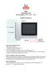
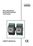
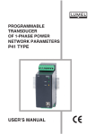
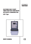
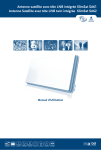
MODULE OF 4 ANALOG OUTPUTS S4AO USER’S MANUAL 1 S4AO-09 User's manual 3 1. APPLICATION The 4-channels analog outputs module is designed to convert numerical data to standard (voltage or current) signals, by means of the MODBUS protocol. The output signals are divided into 2 sets of 2 outputs, which are isolated between themselves. RS485 and USB ports are isolated from outputs signals and the supply. The module setting can be done through USB or one of the RS-485 interface using the available for free eCon program. The S4AO module performs the following functions: • analog output (current and / or voltage, according to the ordering code), • 2 independent interfaces RS-485 Modbus. Each can be configured as Slave or Master, which set to output a signal proportionally to a value read from another Slave device, • short-circuit detection on voltage outputs, • timer counting time work over an upper threshold and beneath a lower threshold, Figure 1: View of the S4AO module S4AO-09 User's manual 4 2. MODULE SET Complete set of the meter includes: • S4AO • user’s manual • guarantee card 1 pc 1 pc 1 pc 3. BASIC REQUIREMENTS, OPERATIONAL SAFETY The symbols in the manual mean: Warning! Warning of potentially hazardous situations. Especially important to be aware of before connecting the device. Failure to follow the directions marked by this symbol could result in serious injuries of the personnel and damage of the device. Caution! Useful notes. The notes should facilitate the operation of the device. Should pay attention, if the device is not working as expected. Possible consequences in case of ignoring information! In terms of operational safety the meter meets the requirements of the EN 61010-1 standard. Comments concerning safety: Assembly and installation of the electrical connections should be conducted only by people authorized to perform assembly of electric devices. The person installing the device is responsible for ensuring the safety of the implemented system. Always check the connections before turning the device on. Opening the device housing gives access to the live parts. The supply must be switched off and the output circuits disconnected before removing the device housing. Removal of the device housing cover during the warranty period voids the warranty. The device is designed to be installed and used in the industrial electromagnetic environment conditions. The building installation should have a switch or a circuit-breaker installed. This switch should be located near the device, easy accessible by the operator and suitably marked. In case of damage, the module can to repaired only by manufacturer's authorized service. Check the correct operation of the device after a repair. before using it for operation. Connection and/or using the device in a way which is not compliant with the user's manual, may cause deterioration of the degree of protection. Maintaining a voltage output on short-cicuit state will make an overheating of the module, and can cause troubles on RS-485 communications. S4AO-09 User's manual 5 4. INSTALLATION 4.1. Mounting The S4AO module can be installed in modular distribution devices on the 35 mm rail bracket. The module enclosure is made of plastic and its dimensions are 53 x 110 x 60.5 mm. There are pluggable terminal blocks on the outside of the module to connect the power supply, the RS-485 port 1 and the analog outputs signals using leads up to 2.5 mm 2. The module dimensions are shown in Figure 2. Figure 2: Module dimensions S4AO-09 User's manual 6 4.2. External Connection Diagrams The module connections are shown in Figure 3. The polarization of the power supply is not needed when the module is supplied by a d.c. voltage. 4 current outputs version 4 voltage outputs version Figure 3: Electrical connections of the S4AO module. 2 set of 1 voltage + 1 current outputs version Legend: 300 V isolation Figure 4: Isolation scheme of the S4AO module. 50 V isolation S4AO-09 User's manual 7 Table 1: LED description LED Description ON / ERROR (green / red) - Light continuously in green: normal operation, - Blink alternatively in green / red: short-circuit detected on one or several voltage outputs. - Light continuously in red: power supply unplugged (self-powered by USB) or error, - Blink in red: calibration error Rx 1 (green) Data receive through RS-485 port 1. Tx 1 (orange) Data transmit through RS-485 port 1. Rx 2 (green) Data receive through RS-485 port 2. Tx 2 (orange) Data transmit through RS-485 port 2. 4.3. Lateral bus To access to the lateral bus, 2 traps must be opened by mean of a screwdriver. Figure 5: Lateral bus traps 5. OPERATION 5.1 Configuration The S4AO module can be configured by Modbus protocol through 3 interfaces: • USB: the device will reply to all address and does not requires power supply. If only USB is plugged without power supply, the analog outputs will stay to 0, the RS-485 interfaces will not be available and the POWER / ERROR led will light continuously in red. This interface is dedicated to configuration and should be unplugged during normal operation. • RS-485 port 1 and port 2: must be configured (Table 4: 4000 Modbus registers) and the S4AO-09 User's manual 8 device must be powered. 5.2 Slave operations In order to use the S4AO module as a Slave device on a RS-485 interface, it has to be configured as follow: • RS-485 port 1 mode (register 4010). (or RS-485 port 2 mode.(register 4017)) set to '0' (Slave), set transmission mode, baudrate address and update changes (register 4016 for port 1, 4023 for port 2), • The outputs values have to be multiplied by 100 and written on 4100 to 4103 registers. For example, to get 5,00 V on a voltage output, write “500” on the corresponding register, • Note that on start, each output is set to its alarm value (register 4112 to 4115), • Eventually, set the high and low value threshold to start the high and low value counters (registers 4104 to 4111), and reset them (registers 4162 to 4170). 5.3 Master operations In order to use the S4AO module as a Slave device on a RS-485 interface, it has to be configured as follow: • RS-485 port 1 mode (register 4010). (or RS-485 port 1 mode.(register 4017)) set to '1' (Master), set transmission mode, baudrate address, the scanning period and the timeout (register 4011 to 4022) and update changes (register 4016 for port 1, 4023 for port 2), • For each selected output, set the scaling parameters (register 4116 to 4131), the Master controlled mode (register 4132 to 4135), the address, the register, the timeout and the type to read (register 4136 to 4159), • The read value as displayed as floats on the 6000 to 6003 registers. • Eventually, set the high and low value threshold to start the high and low value counters (registers 4104 to 4111), and reset them (registers 4162 to 4170). For each interface, the Master server will check if the interface has to work as Master, and if yes, it will check each slave device and address for each analog output which is set to be controlled by the proper RS-485 interface. 5.4 Cooperation with other devices (lateral bus) Once the traps opened (see chapter 4.3. Lateral bus on page 7), the S4AO can be connected to to others LUMEL devices which are also equipped by a lateral bus. All devices can be RS-485 and the Master is connected at an extremity, or one device is set as RS-485 Master and monitors others devices. S4AO-09 User's manual 9 Figure 6: lateral bus connection 5.5 Counters In all version, each output is monitored by 2 counters: one which is incremented on each second if the output value is below a defined level (4104, 4106, 4108 and 4110), and a second which is incremented on each second if the output value is upper a defined level(4105, 4107, 4109 and 4111). The value of each counter is displayed on 2 floats registers: one which show value between 0 and 1,000,000, and a second which is incremented every 1,000,000. The registers are addressed from 6072 to 6110 (see Table 6: Floats Modbus registers p. 25). As example, if the low level threshold of an output is set to 2 (200 on 41xx register) and the high level threshold is set to 10 (1000 on 41xx register), both counters will set up according to the output value: S4AO-09 User's manual 10 Figure 7: High / low value timers thresholds 5.6 Individual characteristic When S4AO Master function is enabled, the individual characteristic allows the conversion of a read value to an analogical value. It is used for imaging the measurements coming from third Slave device to a standard value which can be generated by the S4AO module. The conversion is done by an approximation of a straight line passing through the characteristic parameters points. S4AO-09 User's manual 11 Figure 8: Individual characteristic Example: Convert a voltage value from an energy meter (range 0 to 400 V) to a 0 to 20 mA (“2000” in the 4100 to 4103 register) signal. Set the individual characteristic as follows: X0 – 0 (lower value of the measuring range Slave meter) X1 – 400 (upper value of the measuring range Slave meter) Y0 – 0 (lower value of the analog output) Y1 – 2000 (upper value of the analog output). After enabling the Master feature, the module read out the value and issues proportional signal. 5.7 Short circuits A function is available on SAO-2XXXXX and SAO-3XXXXX to report a low impedance plugged to a voltage output. It launches if the impedance is less than 430 Ω. If one is discovered, the ON / ERROR led will blink alternatively in green and red, register 4160 and 4161 will report it and the corresponding counter register (6072 / 6074) or (6076 / 6078) will be incremented on each second. These registers can not be reset. The short-circuit detection is very sensitive and can also detect a 0 Ohms impedance between a voltage output and the ground, even if this voltage output is set to 0 Volts. 5.8 Timeout Each analog output has a dedicated register which sets a timeout value (in ms x 100) on 4140, 4146, 4152 and 4158 registers. It is disabled when a '0' is set. When enabled, a timer is reset after updating (by an external Modbus Master or when S4AO is set as RS-485 Master). When the counter reaches the set timeout, it switches automatically the output to its alarm value, which is set on th e 4112 to 4115 registers. When S4AO is set to Modbus Master, it is important to set the timeout a ccording to the number of channel to control and to the scan parameters (registers 4013 and 4014 for Port 1, registers 4020 and 4021 for Port 2). S4AO-09 User's manual 12 timeout timer value channel update channel update set alarm value channel update channel update Figure 9: Slave timeout example channel 1 send RS-485 request channel 1 receive RS-485 reply channel 2 send RS-485 request channel 2 receive RS-485 reply channel 3 send RS-485 request channel 3 receive RS-485 reply channel 4 send RS-485 request channel 4 receive RS-485 reply channel 1 send RS-485 request channel 1 receive RS-485 reply timeout 1 timer 1 value set value 1 alarm channel 1 update channel 1 update Figure 10: Master Modbus - too short timeout channel 1 send RS-485 request channel 1 receive RS-485 reply channel 2 send RS-485 request channel 2 receive RS-485 reply channel 3 send RS-485 request channel 3 receive RS-485 reply channel 4 send RS-485 request channel 4 receive RS-485 reply channel 1 send RS-485 request channel 1 receive RS-485 reply timeout 1 timer 1 value channel 1 update Figure 11: Master Modbus – Analog output timeout setting channel 1 update S4AO-09 User's manual 13 When an analog output is controlled by the internal Master feature, its timeout has to be set taking into consideration: - the scanning period of the Master RS-485 (4014/4023 register), - the Master RS-485 timeout (4013/4022 register), - the transmission time, especially if the module works at a low baudrate, - the number of outputs which are controlled by the Master feature (4132/4133/4134/4135 register), - the number of unreplied requests to tolerate before set the timeout value, which depend of the external noise which the module is exposed, - the Slave timeout, which is the time which Slave needs to begin to send its response. S4AO-09 Transmission time[ms ]= User's manual 14 320000 (baudrate [bps ]) response timeout [ ms]=Slave timeout [ms]+Transmissio time [ms] Analog output Timeoutmin = Number of channels to scan × (Number of tolerated unreply +1) × (scanning period + response timeout +transmission time) Always round your results to the upper value. For example, if you calculate a value equal to 811 ms, enter “9” [x 100ms] to the field. S4AO-09 User's manual 15 5.9 Device configuration using e-Con program Figure 12: e-Con program window The e-Con program designed for configuration of the S4AO module is available at the manufacturer's website (www.lumel.com.pl) for free. The module should be connected to a PC via USB cable or one of the RS-485 interface. When the e-Con program starts, select the port on which the device is installed in the area “Communication”, set the transmission parameters (baud rate 9600, mode RTU 8N2 by default), and then click the icon “connect”. Before changing a configuration you should read and save the current configuration for future restoring of the settings. You can save the parameters to a file, read from a file, as well as export the configuration to a pdf file using the eCon menu (Figure 13). Export the configuration to a pdf file Saving the configuration to a file Reading the configuration from file Saving the configuration to a meter Reading the configuration from a meter Figure 13: Read, write and export settings Information about the module S4AO-09 User's manual 16 Connect / disconnect Figure 14: Establishing connection to S4AO module 5.8.1 Configuration parameters After establishing a connection, there are configuration parameters of the module on the right side of the program window. Table 2: e-Con configuration parameters Parameter description Range of parameter change Manufacturer setting Mode Choice of the external RS-485 (Port 1) operation mode: Slave or Master Slave / Master Slave Transmission mode Choice of the external RS-485 (Port 1) transmission mode 8N2 8E1 8O1 8N1 8N2 Choice of the baud rate of the external RS485 (Port 1) baud rate 1200 2400 4800 9600 19200 38400 57600 115200 9600 0.1 – 5 s 0.5 s Parameter name External RS-485 tab Baud rate Timeout after which the Master server Modbus Master: slave response considers that the interrogated device will not timeout reply Modbus Master: slave scanning period Time between each pool from the Master server 0.1 – 30,000 s 0.5 s Modbus slave address Modbus address of the interface when used as Slave 1 - 247 1 Mode Choice of the internal RS-485 (Port 1) operation mode: Slave or Master Slave / Master Slave Transmission mode Choice of the internal RS-485 (Port 1) transmission mode 8N2 8E1 8O1 8N1 8N2 Choice of the baud rate of the internal RS485 (Port 1) baud rate 1200 2400 Internal RS-485 tab Baud rate 9600 S4AO-09 User's manual 17 4800 9600 19200 38400 57600 115200 Timeout after which the Master server Modbus Master: slave response considers that the interrogated device will not timeout reply 0.1 – 5 s 0.5 s Modbus Master: slave scanning period Time between each pool from the Master server 0.1 – 30,000 s 0.5 s Modbus slave address Modbus address of the interface when used as Slave 1 - 247 2 Analog output 1,2,3 and 4 tab Slave mode Mode Low value timer threshold High value timer threshold Settings the way which the output is controlled: directly by an Modbus interface as Slave or by an integrated RS-485 Modbus server. In the second case, the chosen interface has to be prior set as Master. When the analog output is lower that this value, the corresponding counter is incremented on each second. When the analog output is higher that this value, the corresponding counter is incremented on each second. Master mode (Read out through ext. RS485) Slave mode Master mode (Read out through int. RS485) 0.00 – 24.00 mA (current) 0.00 0.00 – 12.00 V (voltage) 0.00 – 24.00 mA (current) 0.00 – 24.00 mA (current) 0.00 – 12.00 V (voltage) 0.00 – 12.00 V (voltage) Alarm value (power on and timeout) Output value in case of power on and timeout. The analog output will take this value when the module turns on, or if the output is not refreshed (by an external Modbus Master or an integrated Master server) after a time specified in the “Timeout” field. Timeout Timeout value. The analog output will take the alarm value if is not updated after the set time. This feature is disable is a '0.0' value is set. 0.0 – 3,000.0 s 0.0 s Output current range Current output only. Define the current range of the output. 0...20 mA 4...20 mA 0...20 mA (current output only) Slave address to check Master mode only. Set the address of the Slave to read. 0...247 0 Slave register to check Master mode only. Set the register of the Slave to read. 0...65535 0 Modbus function Master mode only. Set the Modbus function to use to read the Slave device. 3...4 3 char 8 uchar 8 short 16 ushort 16 long 32 ulong 32 float 32 float 2x16 (3210) float 2x16 (1010) long 2x16 char 8 Data type Master mode only. Set the type of data to read on the Slave. 0.00 – 24.00 mA (current) 0.00 0.00 – 12.00 V (voltage) S4AO-09 User's manual 18 swapped long 2x16 ulong 2x16 u swapped long 2x16 X0 Master mode only. Individual characteristic, point X0 (read through Modbus RS-485 Master). -32768...32767 0 X1 Master mode only. Individual characteristic, point X1 (read through Modbus RS-485 Master). -32768...32767 1 Y0 Master mode only. Individual characteristic, output value corresponding to the X0 point. -327.68...327.67 0.00 Y1 Master mode only. Individual characteristic, output value corresponding to the X1 point. -327.68...327.67 0.01 Reset Counters tab This tab allows to check and reset the low and high value timers. Version equipped with voltage output can also indicate the time during which a short circuit was detected on each output set. Device status This tab is used to show on one window the parameters of the S4AO. Status values This window show the current voltage / current value at the outputs, the value read by RS-485 Master (if enabled) and allow also to update manually each output. Configured values This window shows for each output the read value through Master (if enabled), the timers thresholds, the alarm values, the individual characteristic parameters and the timer values. S4AO-09 User's manual 5.8.2 Status value Figure 15: eCon: Status values 5.8.3 Configured values Figure 16: eCon: configured values 19 S4AO-09 User's manual 20 6. SERIAL INTERFACES 6.1 RS-485Interfaces – list of parameters Both RS-485 interfaces (Port 1 and Port 2) are intended for the configuration and the operations of the module. identifier device address baud rate transmission mode operating mode maximum response time 215 (0xD7) 1...247 1.2, 2.4, 4.8, 9.6, 19.2, 38.4, 57.6, 115.2 kbit/s 8N2, 8E1, 8O1, 8N1 Modbus RTU 100 ms (read) 1000 ms (write) implemented functions - 03 Read Holding Registers - 04 Read Input Registers - 06 Write Single Register - 16 Write Multiple registers - 17 Device identification Factory settings for both interfaces: speed 9.6 kbit/s, mode RTU 8N2. Factory address for Port 1: 1 Factory address for Port 2: 2 Broadcast address: 253 6.2 USB Interface – list of parameters The USB interface is intended only for the configuration of the module. identifier device address baud rate transmission mode operating mode maximum response time 215 (0xD7) reply to all adress compatible with all virtual baud rate, without settings compatible with all virtual mode, without settings Modbus RTU 100 ms (read) 1000 ms (write) implemented functions - 03 Read Holding Registers - 04 Read Input Registers - 06 Write Single Register - 16 Write Multiple registers - 17 Device identification Broadcast address: 253 S4AO-09 User's manual 21 6.3 Map of S4AO module registers In the S4AO module, data are placed in 16 and 32-bit registers. Process variables and module parameters are placed in the address area of registers in a way depended on the variable value type. Bits in 16-bit registers are numbered from the least significant to the most significant bit (b0-b15). The 32-bit registers contain float numbers compliant with IEEE754 standard. Range of the registers is shown in Table 3. The 16-bit registers are shown in Table 4 and Table 5. The 2x16-bits registers with their 32-bit equivalent registers are shown in Table 6. The register addresses shown in the tables are their physical addresses. Table 3: Modbus registers Address range 4000 - 4025 4100 - 4170 6000 - 6110 7000 – 7110 7600 – 7655 Value type Integer (16 bits) Integer (16 bits) Float (2x16 bits, the byte order of 3210) Float (2x16 bits, the byte order of 1032) Float (32 bits) Description Module interfaces configuration. Value set in the 16-bit register. Module operation configuration. Value is set in the two following 16-bit registers. Registers contain exactly the same data, as 32-bit registers of 7500 range. Read only registers. Value is set in the two following 16-bit registers. Registers contain exactly the same data, as 32-bit registers of 7500 range. Read only registers. Value set in the 32-bit register. Read only registers. Table 4: 4000 Modbus registers Register Read/Write address 4000 R Range Description Default 0xD7 Device identifier Output signals: 1: 4 current, 2: 4 voltage, 3: 2 set of 1 voltage + 1 current Software version Bootloader version Serial number (MSB) Serial number (LSB) RESERVED RESERVED Power supply state. 0: device not supplied 1: device supplied and ready for operation RESERVED Port 1 RS-485 mode. 0: Slave 1: Master Port 1 RS-485 transmission mode. 0: 8N2 1: 8E1 2: 8O1 3: 8N1 Port 1 RS-485 baud rate. 0: 1200 1: 2400 2: 4800 0xD7 4001 R 1...3 4002 4003 4004 4005 4006 4007 R R R R R R 4008 R 4009 R 4010 RW 0...1 4011 RW 0...3 4012 RW 1...7 0,1 * 1 0 0 3 S4AO-09 User's manual 4013 RW 1...50 4014 RW 1...30000 4015 4016 RW RW 1...247 0...1 4017 RW 0...1 4018 RW 0...3 4019 RW 0...7 4020 RW 1...50 4021 4022 4023 4024 4025 1...30000 RW R 0..247 0,1 RW 0,1 22 3: 9600 4:19200 5: 38400 6: 57600 7: 115200 Port 1 RS-485 Modbus Master. Slave response timeout (ms*100) Port 1 RS-485 Modbus Master: Slave scanning period (ms*100) Port 1 RS-485 Modbus slave address Port 1 RS-485 parameters update Port 2 RS-485 mode. 0: Slave 1: Master Port 2 RS-485 transmission mode. 0: 8N2 1: 8E1 2: 8O1 3: 8N1 Port 2 RS-485 baud rate. 0: 1200 1: 2400 2: 4800 3: 9600 4:19200 5: 38400 6: 57600 7: 115200 Port 2 RS-485 Modbus master. Slave response timeout (ms*100) Port 2 RS-485 Modbus Master: Slave scanning period (ms*100) Port 2 RS-485 Modbus slave address Port 2 RS-485 parameters update RESERVED Reset all parameters 5 5 1 0 0 0 3 5 5 2 0 0 *) Depends of the outputs version. Table 5: 4100 Modbus registers Register Read/Write address Range Description Default Analog Output 1 value *100 Analog Output 2 value *100 Analog Output 3 value *100 Analog Output 4 value *100 Analog Output 1 low value *100: threshold to start the AO1 low value timer (6080/6082) Analog Output 1 high value *100: threshold to start the AO1 high value timer (6084/6086) Analog Output 2 low value *100: threshold to start the AO2 low value timer (6088/6090) Analog Output 2 high value *100: threshold to start the AO2 high value timer (6092/6094) Analog Output 3 low value *100: threshold to start the AO3 low value timer (6096/6098) Analog Output 3 high value *100: threshold to start the AO3 high value timer (6100/6102) Analog Output 4 low value *100: threshold to start the AO4 low value timer (6104/6106) Analog Output 4 high value *100: threshold to start the AO4 high value timer (6108/6110) Analog output 1: Output value in case of timeout. If 0 0 0 0 4100 4101 4102 4103 RW RW RW RW ** ** ** ** 4104 RW ** 4105 RW ** 4106 RW ** 4107 RW ** 4108 RW ** 4109 RW ** 4110 RW ** 4111 RW ** 4112 RW ** 0 ** 0 ** 0 ** 0 ** 0 S4AO-09 User's manual 4113 RW ** 4114 RW ** 4115 RW ** 4116 RW 4117 RW 4118 RW 4119 RW 4120 RW 4121 RW 4122 RW 4123 RW 4124 RW 4125 RW 4126 RW 4127 RW 4128 RW 4129 RW 4130 RW 4131 RW 4132 RW 0...2 4133 RW 0...2 4134 RW 0...2 -32768 … 32767 -32768 … 32767 -32768 … 32767 -32768 … 32767 -32768 … 32767 -32768 … 32767 -32768 … 32767 -32768 … 32767 -32768 … 32767 -32768 … 32767 -32768 … 32767 -32768 … 32767 -32768 … 32767 -32768 … 32767 -32768 … 32767 -32768 … 32767 S4AO is Master, AO1 will take this value after value specified in AO1_timeout without slave communication. If S4AO is Slave, AO1 will take this value after a specified time without write. Analog output 2: Output value in case of timeout. If S4AO is Master, AO2 will take this value after value specified in AO2_timeout without slave communication. If S4AO is Slave, AO2 will take this value after a specified time without write. Analog output 3: Output value in case of timeout. If S4AO is Master, AO3 will take this value after value specified in AO3_timeout without slave communication. If S4AO is Slave, AO3 will take this value after a specified time without write. Analog output 4: Output value in case of timeout. If SA4O is Master, AO4 will take this value after value specified in AO4_timeout without slave communication. If S4AO is Slave, AO4 will take this value after a specified time without write. Analog output 1, input of individual characteristic of value read through RS-485, point 0 Analog output 1, expected value for individual characteristic, point 0 (x 100) Analog output 1, input of individual characteristic of value read through RS-485, point 1 Analog output 1, expected value for individual characteristic, point 1 (x 100) Analog output 2, input of individual characteristic of value read through RS-485, point 0 Analog output 2, expected value for individual characteristic, point 0 (x 100) Analog output 2, input of individual characteristic of value read through RS-485, point 1 Analog output 2, expected value for individual characteristic, point 1 (x 100) Analog output 3, input of individual characteristic of value read through RS-485, point 0 Analog output 3, expected value for individual characteristic, point 0 (x 100) Analog output 3, input of individual characteristic of value read through RS-485, point 1 Analog output 3, expected value for individual characteristic, point 1 (x 100) Analog output 4, input of individual characteristic of value read through RS-485, point 0 Analog output 4, expected value for individual characteristic, point 0 (x 100) Analog output 4, input of individual characteristic of value read through RS-485, point 1 Analog output 4, expected value for individual characteristic, point 1 (x 100) Analog output 1 mode. 0: No Master control 1: read out through Port 1 RS-485 2: read out through Port 2 RS-485 Analog output 2 mode. 0: No Master control 1: read out through Port 1 RS-485 2: read out through Port 2 RS-485 Analog output 3 mode. 0: No Master control 1: read out through Port 1 RS-485 2: read out through Port 2 RS-485 23 0 0 0 0 0 1 1 0 0 1 1 0 0 1 1 0 0 1 1 0 0 0 S4AO-09 User's manual 4135 RW 0...2 4136 RW 0...1 4137 RW 0...247 4138 RW 0...65535 4139 RW 3...4 4140 RW 0...30000 4141 RW 0...12 4142 RW 0...1 4143 RW 0...247 4144 RW 0...65535 4145 RW 3...4 4146 RW 0...30000 4147 RW 0...12 4148 RW 0...1 4149 RW 0...247 4150 RW 0...65535 Analog output 4 mode. 0: No Master control 1: read out through Port 1 RS-485 2: read out through Port 2 RS-485 0-20 mA / 4-20 mA mode. The minimum value of the output is 0 mA register value is set to 0, and 4 mA when register value is set to 1 **** Analog output 1, Modbus Master: Slave address to check Analog output 1, Modbus Master: Slave register to check Analog output 1, Modbus Master: Function to use to read the Slave Analog output 1: Time out after which AO1 is set to alarm value (register4112). Disabled if set to 0 (ms x 100) Analog output 1, Modbus Master: Slave data type. 0: char 8 1: uchar 8 2: short 16 3: ushort 16 4: long 32 5: ulong 32 6: float 32 7: float 2x16 8: swapped float 2x16 9: long 2x16 10: swapped long 2x16 11: ulong 2x16 12: u swapped long 2x16 0-20 mA / 4-20 mA mode. The minimum value of the output is 0 mA register value is set to 0, and 4 mA when register value is set to 1 **** Analog output 2, Modbus Master: Slave address to check Analog output 2, Modbus Master: Slave register to check Analog output 2, Modbus Master: Function to use to read the Slave Analog output 2: Time out after which AO1 is set to alarm value (register4113). Disabled if set to 0 (ms x 100) Analog output 2, Modbus Master: Slave data type. 0: char 8 1: uchar 8 2: short 16 3: ushort 16 4: long 32 5: ulong 32 6: float 32 7: float 2x16 8: swapped float 2x16 9: long 2x16 10: swapped long 2x16 11: ulong 2x16 12: u swapped long 2x16 0-20 mA / 4-20 mA mode. The minimum value of the output is 0 mA register value is set to 0, and 4 mA when register value is set to 1 **** Analog output 3, Modbus Master: Slave address to check Analog output 3, Modbus Master: Slave register to check 24 0 0 0 0 3 0 0 0 0 0 3 0 0 0 0 0 S4AO-09 User's manual 4151 RW 3...4 4152 RW 0...30000 4153 RW 0...12 4154 RW 0...1 4155 RW 0...247 4156 RW 0...65535 4157 RW 3...4 4158 RW 0...30000 4159 RW 0...12 4160 4161 4162 4163 4164 4165 4166 4168 4168 4169 4170 R R RW RW RW RW RW RW RW RW RW 0,1 0,1 0,1 0,1 0,1 0,1 0,1 0,1 0,1 0,1 0,1 25 Analog output 3, Modbus Master: Function to use to read the Slave Analog output 3: Time out after which AO1 is set to alarm value (register4114). Disabled if set to 0 (ms x 100) Analog output 3, Modbus Master: Slave data type. 0: char 8 1: uchar 8 2: short 16 3: ushort 16 4: long 32 5: ulong 32 6: float 32 7: float 2x16 8: swapped float 2x16 9: long 2x16 10: swapped long 2x16 11: ulong 2x16 12: u swapped long 2x16 0-20 mA / 4-20 mA mode. The minimum value of the output is 0 mA register value is set to 0, and 4 mA when register value is set to 1 **** Analog output 4, Modbus Master: Slave address to check Analog output 4, Modbus Master: Slave register to check Analog output 4, Modbus Master: Function to use to read the Slave Analog output 4: Time out after which AO1 is set to alarm value (register4115). Disabled if set to 0 (ms x 100) Analog output 4, Modbus Master: Slave data type. 0: char 8 1: uchar 8 2: short 16 3: ushort 16 4: long 32 5: ulong 32 6: float 32 7: float 2x16 8: swapped float 2x16 9: long 2x16 10: swapped long 2x16 11: ulong 2x16 12: u swapped long 2x16 Short circuit detected on analog outputs 1 and / or 2 *** Short circuit detected on analog outputs 3 and / or 4 *** Analog output 1: reset the low value timer Analog output 1: reset the high value timer Analog output 2: reset the low value timer Analog output 2: reset the high value timer Analog output 3: reset the low value timer Analog output 3: reset the high value timer Analog output 4: reset the low value timer Analog output 4: reset the high value timer Reset all counters except Short Circuit Counters 3 0 0 0 0 0 3 0 0 0 0 0 0 0 0 0 0 0 0 0 *) 0...1200 for voltage output, 0...2400 for current output. **) 1200 for voltage output, 2400 for current output. ***) Unavailable on 4 current outputs version. ****) Available only if the output is a current output. Table 6: Floats Modbus registers S4AO-09 User's manual Address of Read/ Description 32-bit Write register s Analog output 1 Master mode. Read value from external device 6000/7000 7600 R Address of 16-bit registers 26 Unit 6002/7002 6004/7004 6006/7006 6008/7008 7601 7602 7603 7604 R R R R Analog output 2 Master mode. Read value from external device Analog output 3 Master mode. Read value from external device Analog output 4 Master mode. Read value from external device Analog Output 1 value V / mA * 6010/7010 7605 R Analog Output 2 value V / mA * 6012/7012 7606 R Analog Output 3 value V / mA * 6014/7014 7607 R V / mA * 6016/7016 7608 R 6018/7018 7609 R 6020/7020 7610 R 6022/7022 7611 R 6024/7024 7612 R 6026/7026 7613 R 6028/7028 7614 R 6030/7030 7615 R 6032/7032 7616 R 6034/7034 7617 R 6036/7036 7618 R 6038/7038 7619 R 6040/7040 7620 R 6042/7042 7621 R 6044/7044 7622 R 6046/7046 7623 R 6048/7048 7624 R 6050/7050 7625 R 6052/7052 7626 R 6054/7054 7627 R 6056/7056 7628 R Analog Output 4 value Analog Output 1 low value: threshold to start the low value timer (6080/6082) Analog Output 1 high value: threshold to start the high value timer (6084/6086) Analog Output 2 low value: threshold to start the low value timer (6088/6090) Analog Output 2 high value: threshold to start the high value timer (6092/6094) Analog Output 3 low value: threshold to start the low value timer (6096/6098) Analog Output 3 high value: threshold to start the high value timer (6100/6102) Analog Output 4 low value: threshold to start the low value timer (6104/6106) Analog Output 4 high value: threshold to start the high value timer (6108/6110) Analog output 1: Output value in case of timeout. If S4AO is Master, AO1 will take this value after value specified in 4112 without slave communication. If S4AO is Slave, AO1 will take this value if the analog output 1 is not update after this timeout. Analog output 2: Output value in case of timeout. If S4AO is Master, AO2 will take this value after value specified in 4113 without slave communication. If S4AO is Slave, AO2 will take this value if the analog output 1 is not update after this timeout. Analog output 3: Output value in case of timeout. If S4AO is Master, AO3 will take this value after value specified in 4114 without slave communication. If S4AO is Slave, AO3 will take this value if the analog output 1 is not update after this timeout. Analog output 4: Output value in case of timeout. If S4AO is Master, AO4 will take this value after value specified in 4115 without slave communication. If S4AO is Slave, AO4 will take this value if the analog output 1 is not update after this timeout. Analog output 1, input of individual characteristic of value read through RS-485, point 0 Analog output 1, expected value for individual characteristic, point 0 Analog output 1, input of individual characteristic of value read through RS-485, point 1 Analog output 1, expected value for individual characteristic, point 1 Analog output 2, input of individual characteristic of value read through RS-485, point 0 Analog output 2, expected value for individual characteristic, point 0 Analog output 2, input of individual characteristic of value read through RS-485, point 1 Analog output 2, expected value for individual characteristic, point 1 Analog output 3, input of individual characteristic of value read V / mA * V / mA * V / mA * V / mA * V / mA * V / mA * V / mA * V / mA * V / mA * V / mA * V / mA * V / mA * S4AO-09 User's manual 6058/7058 7629 R 6060/7060 7630 R 6062/7062 7631 R 6064/7064 7632 R 6066/7066 7633 R 6068/7068 7634 R 6070/7070 7635 R 6072/7072 7636 R 6074/7074 7637 R 6076/7076 7638 R 6078/7078 7639 R 6080/7080 7640 R 6082/7082 7641 R 6084/7084 7642 R 6086/7086 7643 R 6088/7088 7644 R 6090/7090 7645 R 6092/7092 7646 R 6094/7094 7647 R 6096/7096 7648 R 6098/7098 7649 R 6100/7100 7650 R 6102/7102 7651 R 6104/7104 7652 R 6106/7106 7653 R through RS-485, point 0 Analog output 3, expected value for individual characteristic, point 0 Analog output 3, input of individual characteristic of value read through RS-485, point 1 Analog output 3, expected value for individual characteristic, point 1 Analog output 4, input of individual characteristic of value read through RS-485, point 0 Analog output 4, expected value for individual characteristic, point 0 Analog output 4, input of individual characteristic of value read through RS-485, point 1 Analog output 4, expected value for individual characteristic, point 1 Short circuit duration on analog outputs 1 and / or 2 (value incremented after 6074/7274 overflows) Short circuit duration on analog outputs 1 and / or 2 (value up to 999 999) Short circuit duration on analog outputs 3 and / or 4 (value incremented after 6078/7278 overflows) Short circuit duration on analog outputs 3 and / or 4 (value up to 999 999) Analog output 1: time during which the analog output issued a signal lower than specified in the 4104 register (value incremented after 6082/7282 overflows) Analog output 1: time during which the analog output issued a signal lower than specified in the 4104 register (value up to 999 999) Analog output 1: time during which the analog output issued a signal upper than specified in the 4105 register (value incremented after 6086/7286overflows) Analog output 1: time during which the analog output issued a signal upper than specified in the 4105 register (value up to 999 999) Analog output 2: time during which the analog output issued a signal lower than specified in the 4106 register (value incremented after 6090/7290 overflows) Analog output 2: time during which the analog output issued a signal lower than specified in the 4106 register (value up to 999 999) Analog output 2: time during which the analog output issued a signal upper than specified in the 4107register (value incremented after 6094/7294 overflows) Analog output 2: time during which the analog output issued a signal upper than specified in the 4107 register (value up to 999 999) Analog output 3: time during which the analog output issued a signal lower than specified in the 4108 register (value incremented after 6098/7298 overflows) Analog output 3: time during which the analog output issued a signal lower than specified in the 4108 register (value up to 1 000 000) Analog output 3: time during which the analog output issued a signal upper than specified in the 4109 register (value incremented after 6102/7102 overflows) Analog output 3: time during which the analog output issued a signal upper than specified in the 4109 register (value up to 1 000 000) Analog output 4: time during which the analog output issued a signal lower than specified in the 4110 register (value incremented after 6106/7106 overflows) Analog output 4: time during which the analog output issued a 27 s * 1 000 000 s s * 1 000 000 s s * 1 000 000 s s * 1 000 000 s s * 1 000 000 s s * 1 000 000 s s * 1 000 000 s s * 1 000 000 s s * 1 000 000 s S4AO-09 User's manual 6108/7108 7654 R 6110/7110 7655 R 28 signal lower than specified in the 4110 register (value up to 999 999) Analog output 4: time during which the analog output issued a signal upper than specified in the 4111 register (value incremented after 6110/7110 overflows) Analog output 4: time during which the analog output issued a signal upper than specified in the 4111 register (value up to 999 999) s * 1 000 000 s *) according to the device version **) Unavailable on 4 current outputs version. This alarm is activated when a load lower than 430 Ω is applied to a voltage output. 7. BEFORE DECLARING A DAMAGE The following table must be checked in case of incorrect symptoms: Symptom Procedure The ON / ERROR led is not lightning Check the connection of the power supply cable The ON / ERROR led is continuously red lightning Check the connection of the power supply cable Table 7: Error description Remarks The module can be supplied via USB for configuration, and analog outputs features are not active The ON / ERROR led is blinking A short-circuit was detected on a 2 counters monitor the overall alternatively red / green voltage output short-circuit time (6072/6074 and 6076/6078) The ON / ERROR led is blinking Memory / calibration error red The module does not communicate with the device master via the RS-485 port. Lack of transmission signaling on Rx 1, Tx 1, Rx 2 or Tx 2 leds. Check if the wire is connected to the appropriate module terminal. Check if the other device is set on the same transmission parameters as the module (baud rate, mode, address). Contact your retailer S4AO-09 User's manual 29 8. SOFTWARE UPDATE The features implemented in the S4AO module enable to upgrade its software using a PC with e-Con software installed. Free e-Con software and the update files are available at the website www.lumel.com.pl. Updating is done via the external RS-485 interface, so the module must be powered. Figure 17: Program window for updating the software Caution! It is recommended to save module settings using e-Con software before upgrading. The Software update features is enabled only on the RS-485 port 1, and the module must be supplied during the update process. When you start the e-Con program (Figure 12), set the communication parameters in the Communication field at the left side of e-Con window, and then click connect button. The module will be automatically recognized. The parameters should be read and saved to a file for later restoration using the S4AO – configuration field. Next select Update firmware from the menu at the top. The window of the LUMEL UPDATER (LU) program will open (Figure 17). S4AO module is supported with LU from version 1.17. Using this program, select the correct port on which the S4AO module was installed and press the Connect button. The informations about the progress of the update process are available in the Messages window. The message Port opened is displayed when the port is open properly. The LU program will display information about the software version and the version of the bootloader when the meter is properly detected. At this point, you should select the correct module upgrade file by pressing the […] button. If the correct file is selected, the LU program will display a message File opened. Press Send button. The LU program shows a progress bar and the S4AO will blink with green diode during the software update. The module restarts, restores the manufacturer settings and goes to normal operation after the upgrade process is successfully completed. Information Done and duration of the update will appear in the LU program window. In the next step, you can restore previously saved settings of the module using e-Con software. S4AO-09 User's manual 30 Caution! Turning module supply off during upgrade process may result in permanent damage! 9. TECHNICAL DATA Output values ranges: Current output programmable: current (maximal range) 0...20...24 mA or 3.75...4...20...24 mA load resistance: 0...500 Ω disposable voltage: 15V basic error: 0.2 % of range resolution: 0.05 % of range Voltage output programmable: voltage (maximal range) 0...10...12 V load resistance: > 500 Ω disposable voltage: 15V basic error: 0.2 % of range resolution: 0.1 % of range Short-circuit endurance: 15 min. max Additional errors: in % of the basic error - from ambient temperature changes Serial interfaces < 0,1% / 10 °C RS485: address 1..247; mode: 8N2, 8E1, 8O1,8N1; baud rate: 1.2, 2.4, 4.8, 9.6, 19.2, 38.4, 57.6, 115.2 kbit/s Use only shielded cable USB for configuration: 1.1 / 2.0, address: all; mode: all; baud rate: all; maximal USB wire length: 3m broadcasting address: 253 transmission mode: Modbus RTU max time to start response: Counters 400 ms (read) 1000 ms (write) resolution: ± 1s on each launch Pulses which hold less than 1 s can be uncounted S4AO-09 User's manual Test voltages: 2210 V a.c. rms: For 1 minute between: Enclosure / Power Supply, RS-485 ports, USB and Analog Outputs Power Supply / RS-485 ports, USB and Analog Outputs 1390 V a.c. rms: For 1 minute between: Analog Outputs / RS-485 ports Analog Outputs / USB USB / RS-485 ports RS-485 port 1 / RS-485 port 2 Protection grade IP: from frontal side IP 50 from terminals IP 00 Power input in the supply circuit: ≤ 7 VA Weight < 0.2 kg Overall dimensions 53 X 110 X 60 mm Rated operating conditions: - supply voltage 85...253 V a.c. 40..400 Hz; 90...300 V d.c. 20...40 V a.c. 40...400 Hz, 20...60 V d.c. - ambient temperature -10 ... 23 ... +55 °C - storage temperature - 25 ... +85 °C - humidity < 95% (condensation not permissible) - external magnetic field 0..40 ..400 A/m - working position vertical - warm-up time 30 min. Electromagnetic compatibility: - noise immunity acc. to EN 61000-6-2 - noise emission acc. to EN 61000-6-4 Safety requirements: according to EN 61010-1 standard • isolation between circuits basic • installation category III, • pollution grade 2, • maximum phase-to-earth operating voltage: - for supply circuit 300 V - for remaining circuits 50 V • altitude a.s.l. < 2000 m 31 S4AO-09 User's manual 32 10. ORDERING CODE Table 8: Ordering code Rail-mounted analog outputs module S4AO - X X XX X X Outputs: 4 current outputs: 0/4...20 mA 1 4 voltage outputs: 0...10V 2 2 sets of 1 voltage + 1 current output: 0...10V and 0/4...20mA 3 acc.to customer's requirements* X Supply voltage: 85...253 V a.c. , 90...300 d.c. 1 20...40 V a.c. , 20...60 V d.c. 2 Version: standard 00 custom-made* XX Language: Polish P English E other* X Acceptance tests: without extra quality requirements 0 with an extra quality inspection certificate 1 acc.to customer's requirements* X * After agreeing with the manufacturer ORDER EXAMPLE: Code S4AO-1100E0 means: S4AO - S4AO module, 1 – 4 current outputs, 0..20 mA, 1 – 85..253 V a.c. / d.c. 00 – standard version, E – English version, 0 – no additional requirements. AVAILABLE ACCESSORIES: Accessories: For the S4AO module, you can order: S4AO-09 User's manual • USB CABLE A/miniUSB-B - 1m BLACK; Order code 20-069-00-00150, • lateral bus inter-module connector; Order code 24-171-01-00016, • lateral bus to cable connector; Order code 24-171-01-00017. 33 Export department: tel.: (+48 68) 45 75 139, 45 75 233, 45 75 321, 45 75 386 fax.: (+48 68) 32 54 091 e-mail: [email protected] 26 S4AO-09 LUMEL S.A. ul. Słubicka 1, 65-127 Zielona Góra, POLAND tel.: +48 68 45 75 100, fax +48 68 45 75 508 www.lumel.com.pl, e-mail: [email protected]