1
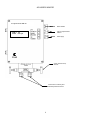
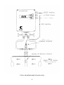
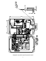
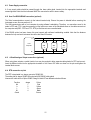
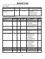
Chell Instruments Ltd
Folgate House
Folgate Road
North Walsham
United Kingdom.
Tel:
Fax:
01692 500555
01692 500088
http://www.chell.co.uk
INSTALLATION AND OPERATING MANUAL
AIR INGRESS MONITOR
AIM – 100
AND VARIANTS
900005-3.6
Please read this manual carefully before using this instrument.
Use not in accordance with the instructions in this manual may result in the protection offered to the user being impaired.
INDEX
SECTION 1 ........................................................................................................................................................................................... 3
GENERAL DESCRIPTION ................................................................................................................................................................ 3
1.1 INTRODUCTION ............................................................................................................................................................................. 3
1.2 GENERAL INFORMATION ............................................................................................................................................................... 3
SECTION 2 ........................................................................................................................................................................................... 5
SPECIFICATIONS .............................................................................................................................................................................. 5
2.1 GENERAL ...................................................................................................................................................................................... 5
2.2 MEASUREMENT PERFORMANCE ................................................................................................................................................... 6
2.3 TEMPERATURE ............................................................................................................................................................................. 6
2.4 ABSOLUTE PRESSURE ................................................................................................................................................................... 6
2.5 DIFFERENTIAL PRESSURE ............................................................................................................................................................. 6
2.6 CALCULATED AIR INGRESS ........................................................................................................................................................... 6
2.7 CALCULATED % AIR. .................................................................................................................................................................... 7
2.8 4 -20 MA OUTPUTS. .................................................................................................................................................................... 7
2.9 CALCULATED MASS FLOW (AMFM VARIANT). ........................................................................................................................... 7
2.10 SERIAL OUTPUTS. ....................................................................................................................................................................... 8
2.11 HIGH ACCURACY OPTION ........................................................................................................................................................... 8
SECTION 3 ........................................................................................................................................................................................... 9
PRINCIPLE OF OPERATION .......................................................................................................................................................... 9
3.1
3.2
3.3
3.4
3.5
3.6
3.7
INTRODUCTION ............................................................................................................................................................................ 9
TEMPERATURE MEASUREMENT ................................................................................................................................................... 9
ABSOLUTE PRESSURE MEASUREMENT......................................................................................................................................... 9
DIFFERENTIAL PRESSURE MEASUREMENT ................................................................................................................................... 9
ANALOGUE MEASURING CIRCUITS............................................................................................................................................... 9
DIGITAL CONTROL ....................................................................................................................................................................... 9
ANALOGUE OUTPUTS ................................................................................................................................................................... 9
SECTION 4 ......................................................................................................................................................................................... 12
INSTALLATION AND INTERCONNECTIONS ........................................................................................................................... 12
4.1 IMPORTANT SAFETY NOTICE...................................................................................................................................................... 12
4.2 INTRODUCTION .......................................................................................................................................................................... 12
4.3 UNPACKING ............................................................................................................................................................................... 12
4.4 PREPARATION FOR OPERATION................................................................................................................................................... 12
4.5 PITOT TUBE LOCATION AND MOUNTING...................................................................................................................................... 12
4.7 VACUUM LINE CONNECTION ...................................................................................................................................................... 13
4.8 RTD CONNECTION TO PITOT TUBE ............................................................................................................................................. 13
4.9 INTERCONNECTIONS AIM–100 .................................................................................................................................................. 14
4.10 RTD CONNECTION ................................................................................................................................................................... 14
4.11 POWER SUPPLY CONNECTION .................................................................................................................................................. 15
4.12 USER PORT RS232/RS485 CONNECTION (OPTIONAL) .............................................................................................................. 15
4.13 4-20MA ANALOGUE OUTPUT CONNECTIONS (OPTIONAL) ........................................................................................................ 15
4.14 RTD CONNECTION AT PITOT. ................................................................................................................................................... 15
4.15 SERIAL PORT CONNECTIONS FOR AIM AND PC. ...................................................................................................................... 16
SECTION 5 ......................................................................................................................................................................................... 17
INSTRUMENT CONFIGURATION AND INITIAL SET UP....................................................................................................... 17
1
5.1 INSTRUMENT SET UP .................................................................................................................................................................. 17
5.2 PIPE DIAMETER .......................................................................................................................................................................... 17
5.3 DIFFERENTIAL TRANSDUCER ZERO............................................................................................................................................ 17
5.4 SERIAL INTERFACE SETTINGS .................................................................................................................................................... 17
SECTION 6 ......................................................................................................................................................................................... 18
FRONT PANEL OPERATION ........................................................................................................................................................ 18
6.1 INTRODUCTION ........................................................................................................................................................................... 18
6.2 ALTERNATIVE DISPLAY INFORMATION ...................................................................................................................................... 18
6.3 DIFFERENTIAL PRESSURE INPUT ZERO FUNCTION ...................................................................................................................... 19
6.4 CONDITION AND ERROR CODES ................................................................................................................................................. 20
SECTION 7 ......................................................................................................................................................................................... 22
SERIAL INTERFACE ....................................................................................................................................................................... 22
7.1
7.2
7.3
7.4
7.5
7.6
INTRODUCTION .......................................................................................................................................................................... 22
BASIC COMMUNICATION PROTOCOL........................................................................................................................................... 22
BASIC COMMANDS .................................................................................................................................................................... 22
4 - 20MA OUTPUT CONTROL ..................................................................................................................................................... 23
SERIAL INTERFACE CONTROL COMMANDS ................................................................................................................................ 24
OTHER COMMANDS ................................................................................................................................................................... 25
AIM–100 COMMAND SET SUMMARY........................................................................................................................................ 26
BASIC COMMANDS ........................................................................................................................................................................... 26
CONFIGURATION AND SETUP COMMANDS ........................................................................................................................................ 26
SECTION 8 ......................................................................................................................................................................................... 27
SERVICE AND CALIBRATION ..................................................................................................................................................... 27
8.1 SERVICE..................................................................................................................................................................................... 27
8.2 CALIBRATION............................................................................................................................................................................. 27
8.3 PNEUMATIC MAINTENANCE ....................................................................................................................................................... 27
8.4 DIFFERENTIAL PRESSURE ZERO ................................................................................................................................................. 27
8.5 ADJUSTMENT ............................................................................................................................................................................. 27
8.6 CLEANING................................................................................................................................................................................... 27
8.7 PREVENTIVE MAINTENANCE ...................................................................................................................................................... 27
Chell Part No. : 900005 Issue 3.6
28th September 2011
ECO No 0651
Due to a policy of continuously updating products, this manual may contain minor differences in specification,
components and circuit design to the actual instrument supplied.
2
Section 1
General Description
1.1 Introduction
Chell's AIM-100, microprocessor controlled Air Ingress Monitor is a high precision measuring instrument featuring multimeasurement capability with both analogue and digital interfacing. The instrument provides measurement and readout of
duct temperature, absolute pressure and differential pressure relating to the steam/air flow. The on-board microprocessor
not only controls the measurement sequence and front panel interface, but also calculates for display the air ingress and
percentage air of the total mass flow.
As of firmware version 2.08 an Air Mass Flow Meter variant (AMFM) exists who’s main functionality is purely looking at
mass flow rather than air ingress (it is used in applications where the gas is just air, there will be no steam to check for
steam/air mix). The percentage air display is disabled in this variant.
The instrument may be powered from a wide range line supply voltage and frequency (100-240 V AC, 50/60Hz).
There are five 4-20mA outputs, relating to each of the measured and calculated parameters, that are available to drive a
chart recorder or remote panel meter. With user programmable offset and scaling factors, the range of the chart recorder
may be optimised.
A digital serial interface, RS232 or RS485, provides interconnection to a host computer. The computer may then extract
data from the AIM as required or be used to configure the AIM.
1.2 General Information
If the instrument is supplied with a pitot tube the following accessories will be included:4 metres ½" O.D. Nylon Tube ( 2 off )
4 metres AIM to RTD cable with appropriate terminations.
The following accessories are available for use with the Air Ingress Monitors:Pitot tube with RTD fitted, available in various lengths ranging from 50mm to 1800mm
½" NPT to ½" O.D. tube fitting - male or female
½" O.D. Nylon tube
5 valve manifold
Shut off valve with quick connect
Insertion ball valve
3
AIR INGRESS MONITOR
Air Ingress Monitor AIM 100
RS232 / RS485
187.5
4-20 mA Output and RTD
Interface
kg/Hr
Power Supply
3 valve (optional 5 valve)
manifold.
Connection to velocity and
absolute pressure sensor
4
Section 2
Specifications
2.1 General
Mechanical:
Model
AIM-100
Height
(mm)
330
Width
(mm)
230
Depth
(mm)
110
Weight
Construction
(kg)
10
Diecast Aluminium sealed enclosure with sealed keypad,
hinged lid.
Connections via screw terminals.
Power Supply:
Line voltage:
Line frequency:
Consumption:
Protection:
100 - 240 V AC.
50/60 Hz.
less than 20 VA
T1.6A anti surge fuse (internal)
Operating conditions:
Operating temperature range:
Storage temperature range:
Maximum Relative humidity:
Warm up time to full accuracy:
+5°C to +50°C (40°F to 122°F)
-40°C to +70°C (-40°F to 158°F)
95% at 50°C (non condensing)
< 2 hours (assumes unit already stabilised at ambient).
Pressure Ports:
AIM-100
2 x 0.5" Swagelok on 3 valve manifold.
Pitot tubes:
Pitot tubes are available from 50mm up to 1800mm, depending on model type.
Read rate:
1 complete set of readings is taken and calculations performed once per second.
5
2.2 Measurement Performance
The following specifications are valid over an instrument ambient temperature range of 5 to 50°C and within 1 year of
calibration at between 20 and 25°C. Accuracy figures quoted include traceability to National Standards.
It is also assumed that the installation and orientation of the Pitot tube is correct. It should be lower than the AIM-100.
The AIM should be mounted vertically with the vacuum ports downwards (as per calibration). Pitot should be mounted
'normal' to the horizontal pipe with ports uppermost. Pitot should be aligned with the flow. Pneumatic lines should be less
than 10m in length and positioned such that condensation cannot collect and water traps form. Pipe disturbances (bends,
intersections, gate valves) must be greater than 12 pipe diameters upstream and greater than 4 pipe diameters
downstream. The pitot length must match the internal pipe diameter. The RTD cable should be less than 10m in length.
2.3 Temperature
100 Ω PRT to DIN 43760 (BS 1904:1984)
0 to 70°C.
±0.15°C
±0.3°C
°C, °F
Transducer type:
Temperature range:
Transducer error:
Overall error:
Display units
2.4 Absolute Pressure
Transducer type:
FS ranges:
Manufacturer's Accuracy:
Display Units:
Absolute Capacitance Manometer
100 Torr giving 10V output (Optional 1000 Torr giving 10V output)
±0. 5% reading
±0.03%reading/°C ±0.005%FS/°C
mbar, in Hg, kPa, Torr
2.5 Differential Pressure
(within 1 month of "input zero". It is also assumed that the transducer has not been over pressurised)
Transducer type:
FS range:
Error:
Differential Capacitance Manometer fitted into a heated enclosure.
1 Torr ( Optional 10 Torr).
±0.3% reading
±0.04% reading/°C ±0.1% FS/°C
Nominal 55 °C, stability ±0.2°C.
mbar, mmH2O, inH2O, Pa, Torr
Heater temperature:
Display Units:
2.6 Calculated Air Ingress
The actual uncertainty is dependent on the specific operating conditions within the pipe, and is typically 10 lbs/hr.
Uncertainty:
for pipe internal diameters ≤ 18"; less than 34 lbs/hr over the range:
10 to 40°C steam temperature,
15 to 120 mbar absolute pressure,
0.5 to 5 mmH2O differential pressure,
provided that %air is >10% and <50% and total mass flow <2000 lbs/hr.
Display units:
lbs/hr, kg/hr, scfm, slpm
6
2.7 Calculated % air.
Uncertainty:
for pipe internal diameters ≤ 18"; less than 2 % over the range:
10 to 40°C steam temperature,
15 to 120 mbar absolute pressure,
provided that %air is >10% and <50%
2.8 4 -20 mA Outputs.
Resolution:
Uncertainty:
Compliance:
better than 1 in 2000 for 0 to 20 mA (< 10µA)
±0.25% of calculated value
Maximum load resistance 600Ω.
(±6V wrt earth for both I+ and I-).
Equivalence between output current and measured parameter: (assumes user offset is zero, user gain is unity)
Parameter
Units
Current Output
Air Ingress
0 to 1000 lbs/hr
0 to 500 kg/hr
4 to 20mA
4 to 20mA
Air Mass Flow
(AMFM variant)
0 to 1700 slpm
0 to 130 kg/hr
4 to 20mA
4 to 20mA
Temperature
0 to 70 °C (32 to 158 °F)
4 to 20mA
Absolute Pressure
0 to FS (100 Torr)
(0 to 133.322 mbar)
(0 to 3.937 inHg)
(0 to 13.3322 kPa)
0 to FS (1000 Torr)
(0 to 1333.22 mbar)
(0 to 39.37 inHg)
(0 to 133.322 kPa)
4 to 20mA
Differential Pressure
0 to FS (1 Torr)
(0 to 1.33322 mbar)
(0 to 13.595 mmH2O)
(0 to 0.53524 inH2O)
(0 to 133.322 Pa)
0 to FS (10 Torr)
(0 to 13.3322 mbar)
(0 to 135.95 mmH2O)
(0 to 5.3524 inH2O)
(0 to 1333.22 Pa)
4 to 20mA
% air
0 to 100 %
4 to 20mA
Out of range signals and error conditions are indicated by <1mA.
2.9 Calculated Mass Flow (AMFM variant).
The principal source of error will be dependant onthe flow within the pipework and the repeatability and accuracy of the
pitot tube used. The instrumentation will contribute approximately 0.5% FS error. Actual achievable uncertainty is likely to
be in the region of 2-5% FSD.
7
2.10 Serial Outputs.
User RS232 or RS485
For connection to PC for data logging, setup, calibration etc.
Selection of RS232/485 via configuration command.
Baud rates available 300, 1200, 2400, 4800, 9600, 19200, 38400, 57600
1 Start, 1 Stop, 8 data bits, No parity.
2.11 High Accuracy Option
This option replaces the compensated absolute pressure sensor with a heated absolute pressure sensor. The following
specifications change:
Measurement performance.
The following specifications are valid over an instrument ambient temperature range of 10 to 30°C and within 1 year of
calibration at 20°C.
Absolute Pressure.
Transducer type:
FS ranges:
Accuracy:
Heater Temperature:
Heated Absolute Capacitance Manometer
100 Torr giving 10V output (Optional 1000 Torr giving 10V output)
±0.15% reading
±0.02%reading/°C ±0.005%FS/°C
45°C nominal.
Calculated Air Ingress.
The actual uncertainty is dependent on the specific operating conditions within the pipe, and is typically 3 lbs/hr.
Uncertainty:
for pipe internal diameters ≤ 18"; less than 12 lbs/hr over the range:
10 to 40°C steam temperature,
15 to 120 mbar absolute pressure,
0.5 to 5 mmH2O differential pressure,
provided that %air is >10% and <50% and total mass flow <2000 lbs/hr.
8
Section 3
Principle of Operation
3.1 Introduction
The following section gives an outline of the basic principles used in the AIM100.
3.2 Temperature Measurement
The temperature measurement is derived from measuring the resistance of a platinum resistance thermometer (PRT)
located in the pitot tube. Its resistance is compared against an internal precision reference resistor. A 4-wire
measurement is taken to eliminate unknown lead and contact resistance's. From standard curves for resistance against
temperature, the equivalent temperature may then be calculated.
3.3 Absolute Pressure Measurement
The absolute pressure from the static side of the pitot is measured by a capacitance diaphragm transducer. It's all metal
construction is corrosion resistant with only Inconel and 316 stainless steel being exposed to the steam/air mixture.
The 0 to 10V output proportional to the absolute pressure is then measured by the analogue circuits.
3.4 Differential Pressure Measurement
The differential pressure developed across the pitot due to the passing flow, is measured using a differential capacitance
manometer of similar construction to the absolute sensor above. To eliminate the possibility of vapour condensing in the
transducer, it is enclosed in a controlled heated enclosure.
The 0 to 10V output proportional to the differential pressure is once again measured by the analogue circuits.
3.5 Analogue Measuring Circuits
Each signal from the above transducers is buffered and scaled before being fed to the 16 bit analogue to digital
converter. To remove short term fluctuations in the differential pressure signal there is both an analogue and digital filter
associated with this channel.
3.6 Digital Control
The sequence of measuring each transducer, calibrating, converting to displayed units and calculation of the air ingress,
as well as the front panel key operation, information display and serial interface are all controlled by an ST10 derived
microprocessor.
During the power up sequence the contents of the setup and calibration memory are verified. As the unit is intended for
continuous use they are also reverified every minute.
3.7 Analogue Outputs
The instruments 4-20 mA outputs are essentially a four wire transmitter with the loop power derived internally. The
current output signals can therefore drive a passive resistive load. Five 4-20 mA outputs represent the calculated air
ingress, percentage air, differential pressure, absolute pressure and temperature. A programmable offset and scaling (for
each output) enables the recorder range to be optimised.
9
Air Ingress Monitor AIM100
TYPICAL AIR INGRESS MONITOR INSTALLATION
10
PERMANENT AIR INGRESS MONITOR MOUNTING GUIDE
11
Section 4
Installation and Interconnections
4.1 Important Safety Notice
The power supply must be earthed to prevent the risk of an electric shock. Correctly rated fuses should always be used.
A suitable mains isolation switch and circuit breaker should always be mounted near to the instrument.
Ensure that the mains supply is isolated before the cover is removed, for any servicing. Due to the presence of high
voltages inside the instrument NO internal adjustments should be made while the instrument is connected to a mains
supply. If adjustments are required they should be performed by suitably trained personnel only.
Never use the instrument near water, and, if water is spilled into the instrument, turn off the power supply immediately to
prevent damage. Always mount the instrument to allow for adequate ventilation to avoid over-heating. When connecting
the pneumatic lines, always ensure that the compression fittings are assembled correctly and avoid over or under
tightening. Nylon tubing should be kept away from heat as it can cause weakening and possible failure.
If you have any queries as to the safety procedures of the instrument, please contact Chell Instruments Ltd for
assistance.
4.2 Introduction
This section contains information and instructions for unpacking and installing the Chell AIM-100 Air Ingress Monitor.
4.3 Unpacking
Every care is taken in the choice of packing material to ensure that the equipment arrives in perfect condition.
If the equipment has been subject to excessive mishandling in transit, the fact will probably be visible as external
damage, the shipping container and cushioning material should be kept for the carrier's inspection.
Unpack the equipment and check for external damage to the case, fittings etc. If damage is found notify the carrier and
sales agent immediately.
4.4 Preparation for operation
The instrument should be mounted above the pitot so that the connecting pneumatic lines will allow any condensation to
drain away from the measuring instrument.
Mounting holes in the rear panel are available to secure the instrument in a fixed position, access being gained by
removal of the front panel. The instrument should be mounted vertically with the vacuum ports downward. The use of
shock mounts is recommended if the instrument is to be located on a surface that is subject to vibration.
4.5 Pitot tube location and mounting
Select a location where there will be sufficient clearance for the installation of the pitot and vacuum connections in a
horizontal pipe run. The pitot must be installed vertically at right angles to the pipe run and across the pipe diameter, with
connections uppermost. To avoid noisy signal outputs do not locate the pitot in a pulsating flow and position in an area of
least vibration. It should also be ensured that the pitot is mounted below the measuring instrument to prevent
condensation from entering the transducers, and water traps forming.
12
In order to meet the quoted accuracy figures, the distances of the pitot from disturbances in the pipe (e.g. bend, pipe
intersection, gate valve) must not be less than 12 pipe diameters upstream and not less than 4 pipe diameters
downstream. If it is fitted within distances less than those above, then the absolute accuracy may be downgraded but
repeatability of the measurement will still be excellent due to the inherent stability of the instrument.
1. Make a clean 35mm (1 3/8") diameter hole in the duct for the pitot.
2. Tack-weld the threaded fitting over the hole. Using a suitably threaded piece of pipe, ensure concentricity of the fitting
and alignment for vertical mounting of the pitot across the duct diameter.
3. Complete the welding of the fitting.
4. Slide the compression fitting assembly onto the pitot.
5. Insert the pitot through the welded fitting into the duct until it touches the opposite internal wall.
6. After applying the appropriate sealant to the threads of the compression fitting, gently tighten into the welded fitting.
7. Turn the pitot until the indentation marks on the head are positioned downstream of the flow
O
H
Flow Direction
L
O
8. Fully tighten the compression fitting whilst ensuring that the pitot does not turn.
9. Check that the pitot is correctly installed and aligned.
4.7 Vacuum Line connection
Ensure that the vacuum lines slope downward from the measuring instrument to the pitot and that there are no loops
where condensation could collect. Connect the upstream side of the pitot ( marked 'H') to the port marked '+' on the
instrument. Likewise connect the downstream side of the pitot ( marked 'L') to the port marked '-'.
For fixed installations, the vacuum lines should run where it is free from vibration or damage and should be supported
over its entire length.
4.8 RTD connection to pitot tube
Remove the sealing cap from the RTD plug located on the head of the pitot. Connect the RTD cable, ensuring a good fit
so that the connection is fully sealed.
13
4.9 Interconnections AIM–100
The AIM–100 provides M20 threads to allow the fitting of suitable cable glands or flexible conduit. The instrument is
supplied with blanks fitted which should be replaced as required. The cable glands chosen should be compatible with the
cable diameter.
After the wires have been passed through the cable gland, and terminated the gland should be tightened to provide a
moisture proof seal.
Terminal Connector Enclosure
4.10 RTD connection
Insert the free end of the RTD cable through the cable gland one up from the bottom. Insert the different coloured wires
into the appropriate terminals of the RTD block as shown on the diagram above and tighten the terminal block screws.
The cable screen should be connected to the guard terminal.
14
4.11 Power Supply connection
A 3 core supply cable should be passed through the lower cable gland, inserted into the appropriate terminals and
screws tightened. Note that the instrument MUST be connected to earth to ensure safety.
4.12 User Port RS232/RS485 connection (optional)
The Serial communications connect via the internal terminal strip. Ensure the power is isolated before removing the
instrument covers. Also see section 4.15.
The AIM communicates with a host computer by using software handshaking. Therefore no connections need to be
made to RTS and CTS. It may be necessary to loop back one or more of the handshake lines on the cable connector at
the computer end (DSR - DTR and CTS - RTS) so that time out errors are eliminated.
If the RS485 option has been chosen this must operate with software handshaking enabled. Note that the distance
between the loop and each instrument should be less than 300 metres.
Tx
+
-
Host
Computer
Rx
+ Rx -
+ Rx -
+ Rx -
AIM
AIM
AIM
+ Tx -
+ Tx -
+ Tx -
+
4.13 4-20mA Analogue Output connections (optional)
When using these outputs a conduit junction box may be required to allow separate cable glands for RTD and current..
Insert the different wires into the appropriate terminals of the Current O/P block as shown on the pcb and tighten the
terminal block screws.
4.14 RTD connection at pitot.
The PRT is terminated in a Jaeger connector 533801006.
The mating half is Jaeger 530801006 socket with 530332006 cable gland.
Interconnect cable is 4m of Alpha 5098C 20swg foil shield 5.7mm diameter wired as follows:
Function
M+
I+
IMGuard
Jaeger
1
2
3
4
Colour
Red
Yellow
Green
Black
Screen
15
4.15 Serial Port Connections for AIM and PC.
A complete list of all the RS232 connections is given in the table below.
AIM-100
Signal
Com
Tx (Data Out)
Rx (Data In)
-
Connects
to
Signal
PC
25 way male
9 way male
0V
7
5
Rx (Data In)
Tx (Data Out)
3
2
2
3
CTS (Input)
RTS (Output)
5
4
8
7
DSR (Input)
DTR (Output)
6
20
6
4
Note that it is necessary to connect an output from the AIM to an input on the PC. Similarly an output from the PC
connects to an input on the AIM. Therefore Tx on the AIM connects to Rx at the PC.
Depending on the exact configuration of the PC it may be necessary to join DTR and DSR at the computer.
16
Section 5
Instrument Configuration and Initial Set up
5.1 Instrument Set Up
After installation the set up of the instrument needs to be checked and modified if necessary.
5.2 Pipe Diameter
To check the pipe diameter setting, simultaneously press the Duct Temperature and Air Content keys. The display will
now indicate the pipe diameter in millimetres. If this is incorrect then see section 7.6 on how to change the setting.
5.3 Differential Transducer Zero
After the instrument has been allowed to warm up for at least 2 hours it is necessary to zero the differential transducer.
See section 6.3
5.4 Serial Interface Settings
If the serial interface is to be used, check the baud rate by simultaneously pressing the Duct Temperature and Absolute
Pressure keys. The display now indicates the current setting. The host computer should be set to the same setting.
Changing the baud rate requires that communication is established at the current setting before issuing a new command.
To change the baud rate see section 7.5.
The unit is supplied with a serial port address of 'a'. If a multiple installation of AIMs on a RS485 network has been
configured then it will be necessary to set each unit to a different address.
To change the unit address see section 7.5.
The serial interface can use an RS232 protocol or RS485 protocol. The default is RS232.
To check and change the protocol see section 7.5.
17
Section 6
Front Panel Operation
6.1 Introduction
The front panel contains a 4 digit 1" red LED 7 segment display plus 5 legends to indicate the units of the measurement.
Also on the front panel is the keypad which consists of 4 momentary action IP65 sealed keys labelled:
Duct Temperature,
Absolute Pressure,
Differential Pressure,
Air Content.
With no front panel keys pressed the instrument will display Air Ingress / Air Mass Flow in the units indicated by the right
hand legend.
Pressing either of the Duct Temperature, Absolute Pressure, Differential Pressure or Air Content keys will cause the
instrument to display the current temperature as measured by the RTD, the absolute pressure in the duct, the differential
pressure developed across the pitot due to the passing steam/air flow or the percentage air content respectively in the
units as indicated (for the AMFM variant, the Air Content key just displays the Air Mass Flow as default).
When any switch is released the instrument will continue to display the relevant parameter for a further 20 seconds
before reverting to Air Ingress, allowing ample time for any readings to be recorded.
6.2 Alternative Display Information
Key Combination
To Display
Duct Temperature and Air Content
Displays the selected pipe diameter.
Duct Temperature and Differential Pressure
Displays the instrument Software Issue.
Duct Temperature and Absolute Pressure
Displays Serial Interface baud rate setting.
Absolute and Differential Pressure
Selects the Differential Pressure Input Zero function.
18
6.3 Differential Pressure Input Zero function
As the differential pressure produced across the pitot can be very low and the differential transducer is very sensitive to
any leaks in the pneumatic lines it is necessary to ensure that it is correctly zeroed.
To either adjust or check the zero of the transducer perform the following sequence:
1
Close the isolation valves, open the cross-port valve to the differential transducer.
2
Press Differential Pressure key and wait for reading to settle. This may well take 30 seconds.
If the reading is not sufficiently close to zero continue with steps 3 to 8, otherwise goto step 8.
3
Simultaneously press Absolute and Differential keys. The display will indicate 'oooo'.
4
Press Duct Temperature key. The display will indicate ' ooo'.
5
Press Absolute Pressure key. The display will indicate ' oo'.
6
Press Differential Pressure key. The display will indicate ' o'.
7
Press Air Content key. The display will now indicate 'zero'. The instrument will now measure the output
of the differential transducer and subtract this result from all subsequent measurements. Should the
reading be greater than 10% of FS then the zero will fail and the display will indicate ' C71'.
8
Close the cross-port valve to the differential transducer, open the isolation valves, allowing the
differential pressure developed across the pitot to be measured.
19
6.4 Condition and Error Codes
Under certain operational conditions the AIM may be unable to calculate the air ingress, it will then indicate a code on the
display. There are two types of codes, a CONDITION code (preceded with a 'C') is used to indicate an abnormal
operating regime. The table below outlines the codes and suggests possible causes with actions that may be taken. The
other situations that may be reported are ERRORS (proceeded with a 'E'). These indicate that there is an internal
processing problem with the measurements taken. In this case check internal fittings and sensors and if this fails to solve
the problem, contact the AIM service centre.
Note: Condition and Error codes marked with an asterisk (*) do not occur in the AMFM variant because they are not
applicable for the typical applications of that variant.
Condition codes that indicate an abnormal operating regime.
C51 *
C52
C53
C54
C55
Absolute pressure is greater than 500 Torr. Air flow rates will not be meaningful at these levels.
A possible reason is that the turbine/generator unit is off-load or running up to/down from load.
If, however, the condenser is known to be under running conditions, then :
check the `-ve' or `L' measurement vacuum line for air leaks. Make a visual inspection
from the Pitot head to the AIM. On fixed AIM models, isolate the `-ve' port at the AIM
and cross port the `+ve' line by opening the equalising valve. If the absolute pressure
changes to a sensible reading then check `-ve' line for leaks downstream of the AIM
isolation valve.
Absolute pressure over range, 110% full scale.
The accuracy of the absolute pressure sensor is out of limits. The validity of this measurement
should be considered.
check for possible water blockage/clogging by purging the Pitot and vacuum lines to
atmospheric pressure. Protect the differential pressure sensor, if possible, whilst
purging.
check the Pitot `-ve' line for leaks.
Isolate Pitot and disconnect`-ve' line. Apply suction and observe absolute pressure
sensor response.
Temperature over range, greater than 70°C (160°F).
carefully check the extraction pipework for the possibility of a genuinely high
temperature.
check RTD connections for a bad circuit.
Temperature less than zero.
carefully check the extraction pipework for the possibility of a genuinely low
temperature.
check RTD connections for a bad circuit.
Differential pressure over range, 110% full scale.
This could be a genuine condition due to a high flow in the extraction pipe. This flow is a
combination of air and steam. Either the air in leakage is high, steam carryover is high ( due to
steam breakthrough or steam bypass conditions ), or both.
However, due to the sensitivity of this measurement, it would be prudent to :
check the vacuum lines and connections for leaks. It is more likely to be a leak on the
`+ve' or `H' line, giving a higher pressure on the `+ve' side of the differential sensor. Use
the isolation and cross porting technique ( C51 ) to identify a leak condition.
check for water blockage/clogging in the vacuum lines and Pitot. Purge these lines to
atmospheric pressure, protecting the differential pressure sensor if possible.
20
C56
C61 *
C71
Differential pressure equal to, or less than, zero.
This could be a genuine condition with a very low pulsating flow in the extraction pipe. Averaging
of the Differential measurement in the processing is used to smooth this effect out.
Other possible causes should be examined by :
checking the Pitot tube for the correct alignment in the pipe. The high pressure sensing
holes (`H') should face upstream and be in line with the flow direction.
check the `-ve' vacuum line for leaks.
check that the differential sensor `zero' is correct. The sensor may still be warming up to
its elevated operating temperature and therefore have an offset at zero, or a prior
zeroing procedure that accounts for any offset has drifted with the passage of time.
To check this zero, isolate the AIM from the vacuum lines and equalise the pressure
across the two AIM measuring ports. If the zero is in error, follow the procedure in
section 6.4.
`Superheated steam' condition. The measured temperature is higher than the saturation
temperature of the absolute pressure in the extraction pipework. The steam partial pressure is
therefore higher than the absolute pressure and Dalton's Law of Partial Pressures cannot be
applied. This law is the principle on which the Air Ingress Monitor relies to calculate the mass
ratio of steam to air in the pipe.
This condition is probably caused by steam bypassing.
Steps should be taken to eliminate/reduce this condition.
Differential pressure input zero out of range.
The difference between the indicated reading for zero differential pressure input and the
calibration set value is greater than 10% of full scale. The instrument cannot be adjusted to allow
for this degree of offset.
cancel any previous offset using the software commands given in section 7.
wait for the differential sensor temperature to change and bring the indicated offset
within adjustable range.
Error Codes relating to internal processing.
E10
E12 *
Calibration stores are corrupt.
- The instrument must be re-calibrated
Air specific volume equal to, or less than, zero.
E13 *
Steam specific volume equal to zero.
E14
E15 *
Total mass flow equal to, or less than, zero.
[ Only if Pitot constant or pipe diameter is in error ]
In AMFM variant, the error only occurs if Mass Flow is less than zero.
Partial pressure of steam equal to zero
E16 *
Steam/air ratio equals -1.
E22 *
Density of mixture equal to, or less than, zero.
21
Section 7
Serial Interface
7.1 Introduction
The serial interface may be configured as either RS232 or RS485 protocol. RS485 is used where many AIM-100s are
connected to the same serial port of a host computer.
The serial port may be used to control the units set up, e.g. pipe diameter, 4 - 20mA scaling or data format etc. It is also
used to return readings to a host computer either on an ongoing basis or via the optional data logger. For interconnection
details see Section 4.
As supplied the unit is configured for a baud rate of 57600. The baud rate may be displayed on the front panel by
simultaneously pressing the Duct Temperature and Absolute Pressure keys.
7.2 Basic communication protocol
All communication from the computer is in lower case alphanumeric characters, any reply from the AIM is in upper case.
As multiple AIMs may be connected together on an RS485 system, each unit has an address which may be from 'a' to 'h'.
The computer must prefix any command sent with the particular units address. The default address is 'a'. When an AIM
recognises its address, it will respond by echoing back the address plus the ensuing command. Depending on the
command sent the AIM will respond either with data or in the case of a set up command 'OK'. If the AIM does not
recognise the command or it has invalid or an incorrect number of parameters, the AIM will repsond with ‘BADCMD’. If a
command has accompanying parameters then the command must be followed by a space before the parameters are
entered, and parameters must be comma separated. Any other response generally means there has been an internal
comms error (indicated by !BUSY! or !ERROR!). If this type of response persists then refer to the AIM service centre.
NOTE: The symbol ↵ is used to denote a carriage return.
For a summary of each command see page 26.
7.3 Basic Commands
Recall current readings - 'r'
To recall data from address 'a' the host computer needs to transmit 'ar↵'. The AIM will echo this back, then send the
data. The data is returned in one of two formats, where the elements are either '↵' separated or comma separated. The
exact number of digits and position of the decimal point is dependent on the units and the FS range. Details are shown
below.
Format 0 = Original
A xxx.xxx↵
B xxx.xxx↵
C xxx.xxx↵
D xxx.xxx↵
E xxx.xxx↵
Format 1 = Excel CSV
xxx.xxx,xxx.xxx,xxx.xxx,xxx.xxx,xxx.xxx↵
(air ingress, temperature, absolute pressure, differential pressure, % air)
(air ingress / air mass flow)
(temperature)
(absolute pressure)
(differential pressure)
(% air)
The format chosen is controlled by the 'fmt' command under instrument set up.
22
Repeated recall of current readings – ‘rp’
In addition to recalling readings upon request, the AIM can automatically report the readings at a given interval using the
‘rp’ command. The output is the same as with the ‘r’ command. Set the interval by sending ‘rp x↵’ where x is between 0
and 4 as dictated by the following:
0
1
2
3
4
No Interval (use this to disable the repeated recall)
Repeat every second
Repeat every minute
Repeat every hour
Repeat every day
The timing commences from the point at which the ‘rp’ command is entered. The recall setting is remembered through a
power cycle. If the repeated recall is active and the AIM is restarted (due to a power outage, etc.) then the display will
show ‘AO x’, where x is one of the above numbers, to indicate that repeated recall is in operation.
Format of data output - 'fmt'
Data is output from the AIM in one of two formats. To determine the current setting send the command 'fmt?'. The AIM
will reply with a number where:
0
1
Original format
Excel CSV compatible format
To change the current setting send the command 'fmt x' where x is 0 or 1 as listed above.
7.4 4 - 20mA Output Control
The 4 - 20mA outputs are normally used to send a signal to a chart recorder proportional to air ingress. The exact values
that represent particular currents are given in the specification (see section 2.8).
To enable the chart recorder to be more suitably used the user may apply a zero offset and gain correction to control the
range of currents output. There are commands to do this for each of the five outputs available. To apply an offset use the
command ‘co# x.x↵’ and for a scaling correction use ‘cs# x.x↵’, where x.x is the offset or scale (as a floating point value)
and # defines the output to be adjusted, as shown:
d
a
t
p
f
Differential Pressure
Absolute Pressure
Duct Temperature
Percentage Air
Air Mass Flow
The current offset and scale for the outputs may be found by entering ‘co#?↵’ & ‘cs#?↵’, where # is defined as above.
Eg. If working with absolute pressure, the actual current output, Iout, is given by the equation:
Iout = Ugain * ( 16 * Pabs/PabsFS - Uzero ) + 4
23
Worked example of user offset and scaling.
Using absolute pressure as an example. As default 0 mbar is represented by 4 mA and 133.2 mbar is represented by 20
mA. In practice the absolute pressure is only expected to vary between 50 and 60 mbar. It is therefore required that 50
mbar produces 5 mA and that 60 mbar produces 20 mA.
Therefore Pmax = 60, Pmin = 50, Imax = 20, Imin = 5, PabsFS = 133.2 ( Pressure in mbar, current in mA )
First it is necessary to calculate the required scaling by substituting the above values into the following equation:
Ugain = ( Imax - Imin ) / ( ( Pmax - Pmin ) x 16 / PabsFS)
Ugain = ( 20 - 5 ) / ( ( 60 - 50 ) x 16 / 133.2 ) = 12.4875
It is now possible to calculate the required zero by substituting into the following equation:
Uzero = ( Ugain x ( 16 x Pmin / PabsFS ) - Imin + 4 ) / Ugain
Uzero = ( 12.4875 x ( 16 x 50 / 133.2 ) - 5 + 4 ) / 12.4875 = 5.9259
The values for Uzero and Ugain may now be entered using the 'coa5.9259' and 'csa12.4875' commands. The values
already in use can be checked by sending the query commands 'coa?' and 'csa?' to which the AIM will reply with the
stored values. These can only be changed by sending new values. Power cycling or changing the current output
selection does not reset the values.
The default values are 'coa0.0' and 'csa1.0'.
7.5 Serial Interface Control Commands
To change the baud rate it is necessary to send the unit address followed by the command 'bra' and a value n
representing the required baud rate. For example to change to 300 baud on the unit with address 'a' the following string
needs to be sent to the AIM:
abra 300↵
The AIM will reply with 'OK' at the old baud rate and then 'OK' at the new baud rate. All communication should now take
place at the new setting. The default setting is 9600.
baud rate setting
value for n
300
1200
2400
4800
9600
19200
38400
57600
The units baud rate may be discovered by sending the query command 'bra?↵'.
The unit address may be from 'a' to 'h'. To change address use the command 'add x↵' where x is the new address. All
subsequent communication must refer to this address.
The serial interface protocol can be either RS232 or RS485 and is selectable by sending the command ‘pro n↵’, where n
is 0 (RS485) or 1 (RS232). Sending ‘pro?↵’ returns the current protocol setting.
24
7.6 Other Commands
Recall Serial No. - 'asn'
The serial number of the unit may be recalled with the command 'asn?↵'. As supplied this will be the units serial number
allocated by Chell Instruments. It may however be redefined to be a plant or I.D. number if required by sending the
command 'asn xxxx↵' where xxxx is any four characters.
Recall Date of Last Calibration - 'dlc'
When the instrument is calibrated the date is entered into the AIM. This may be recalled to see if the unit requires
recalibrating. The date is recalled with the command 'dlc?↵'. The AIM will reply with the date in the format YYMMDD
where YY is the year, MM is the month and DD is the day. For example 930120 would indicate that the unit was
calibrated on the 20th January 1993.
List All Commands - 'cmd?'
To list all the commands to which the AIM can respond send the command 'cmd?↵'.
Differential Pressure Input Zero - 'idz'
As the differential pressure produced across the pitot can be very low and the differential transducer is very sensitive to
any leaks in the pneumatic lines it is necessary to ensure that it is correctly zeroed. This command is similar to the Input
Zero described in section 6.3 in that it measures the current differential pressure and then subtracts the value from all
subsequent readings. The value of the input zero can be found by using the query command 'idz?↵'. This will return the
value in Torr. The value can be set back to zero, thus applying no zero offset, using the command 'idz 0↵'.
Pipe Diameter – ‘pdi’
The pipe diameter can be changed by using the command ‘pdi x↵’, where x is the diameter, between 1 & 3000mm. The
default is 300mm. For example, to set the pipe diameter to 50mm on the AIM with address ‘a’ enter:
apdi 50↵
To find out the current pipe diameter, enter the query command ‘pdi?↵’
Pitot Tube Type – ‘pit’
The pitot tubes commonly used with the AIM-100 are from Torbar but they come in several model types – one designed
pre-1997 which has 7 holes upstream and several newer versions which have 6 holes upstream (different model
numbers cover the wide range of pipe diameters available). It is also possible to connect a different type of pitot available
from Furness Controls. The selection of which one is being used is important because it dictates the algorithm and
coefficients used to calculate the mass flow.
To select the pitot tube, use the ‘pit x↵’ command, where x is a number between 0 & 4, as follows:
0 = Pre97 Torbar pitot (7-hole)
1 = Model 400/700 Torbar pitot
2 = Furness pitot
3 = Model 300/600 Torbar pitot
4 = Model 500/800 Torbar pitot
To find out the current pitot tube type being used, enter the query command ‘pit?↵’
25
AIM–100 Command Set Summary
For a full explanation of each command refer to previous sections in this manual.
Basic Commands
Purpose
Output Instantaneous Reading
Command
r
Parameter
none
Output Instantaneous Reading
Repeatedly
rp
0-4
Comments
Output format as defined by last
Format command
0 = No repeat
1 = Repeat every second
2 = Repeat every minute
3 = Repeat every hour
4 = Repeat every day
Configuration and Setup Commands
Aim Serial No
Pipe Diameter
Pitot Tube Type
User Serial Port baud rate
Command
asn
pdi
pit
Query
asn?
pdi?
pit?
Parameter
xxxx
1<x<3000
0-4
bra
bra?
300-57600
User Serial Port Address
User Serial Port Protocol
add
pro
add?
pro?
a-h
0-1
Current Output user offset
co#
co#?
Real Number
Current Output user scale
cs#
cs#?
Real Number
Date of Last Calibration
List all Commands
Format of data output
Differential Pressure Input
Zero
dlc
---fmt
idz
dlc?
cmd?
fmt?
idz?
yymmdd
---0-1
optional '0'
26
Comments
Any four characters
1 – 3000 millimetres
0 = Pre97 Torbar pitot (7-hole)
1 = Model 400/700 Torbar pitot
2 = Furness pitot
3 = Model 300/600 Torbar pitot
4 = Model 500/800 Torbar pitot
300, 1200, 2400, 4800, 9600,
19200, 38400, 57600
Effective Immediate
Effective Immediate
0 = RS485
1 = RS232
# indicates which output:
d = Differential Pressure
a = Absolute Pressure
t = Temperature
p = Percentage Air
f = Air Ingress (Mass Flow)
Parameter Format is x.x
# indicates which output:
d = Differential Pressure
a = Absolute Pressure
t = Temperature
p = Percentage Air
f = Air Ingress (Mass Flow)
Parameter Format is x.x
Default
FSV
300
1
57600
a
1
0.0
1.0
FSV
Lists the AIM commands
0=original, 1=Excel
Performs a differential input zero
Option '0' clears current setting
0
Section 8
Service and Calibration
8.1 Service
There are no user serviceable parts, or consumables inside the instrument. Should any difficulties be encountered in the
use of the instrument, it is recommended that you contact Chell Instruments Ltd for advice and instructions.
8.2 Calibration
Calibration is recommended on an annual basis, and should only be carried out by Chell Instruments Ltd.
8.3 Pneumatic Maintenance
Periodic checking of the pipework between the pitot and the AIM should be carried out to ensure that they are free from
any condensation build up. This could cause pipe restriction and interfere with the pressure transmission from the pitot to
the AIM. Leak tests should also be carried out to avoid erroneous pressure readings.
8.4 Differential Pressure Zero
Periodically the zero of the differential pressure transducer should be checked as described in section 6.3.
8.5 Adjustment
There are no user adjustments in the instrument.
8.6 Cleaning
The instruments may be wiped clean with a damp, but not wet, cloth. Ensure the instrument is not left damp.
8.7 Preventive Maintenance
There are no user servicable parts contained within the AIM100. If the instrument is suspected faulty then it should be
returned to Chell Instruments Ltd for fault investigation and repair.
27


![[January] [2010] Oracle Part Number E51573-01](http://vs1.manualzilla.com/store/data/005777075_1-9f1c819619cc4ae74609e937019c49fd-150x150.png)