1
IMU-E604 Manual, Revision G
1.0 Introduction
1.1 Production Description
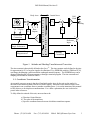
The IMU is a solid state gyro system which models the functions of an attitude gyro and a slaved
heading gyro. The angular rate sensor signals are coordinate transformed and then integrated to
produce attitude and heading outputs that reflect normal aircraft attitude coordinates. The attitude and
heading signal errors are calculated by comparing the attitude and heading with the two vertical
reference pendulums and a triaxial fluxgate magnetometer. These errors are filtered and are used to
adjust sensor biases so that the long-term convergence of the system is to the vertical references and
the magnetic heading. Compensations for centrifugal forces and velocity changes are used to improve
overall stability and accuracy. Note that the velocity input is an optional item. The velocity may be in
either the form of a forward velocity or a GPS velocity (East, North, Up velocity).
The sensors are interfaced to a 68HC11 microprocessor through a 16 bit analog to digital converter.
The analog outputs are from a 12 bit digital to analog converter (although the system’s angular rate
outputs are direct analog connections). An RS-232 serial connection is provided with all units.
Software is available in Macintosh and PC format for calibrating heading.
WARNINGS
Rough handling and high shocks will damage this unit.
Over-voltage and/or reverse voltage may cause damage to the unit.
The unit is gasket sealed but not water-tight. Protect the unit against prolonged
exposure to high humidity and/or water.
1.2 Installation
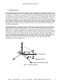
The base plate of the transducer is intended to be mounted on top of a horizontal surface with the
connectors toward the forward direction of the vehicle. A drawing is included at the end of this
manual. The unit may be adhesively mounted at any of its surfaces. If high shock loads are expected
(greater than 20 g's or repeated shocks greater than 2 g's), the appropriate shock mounting should be
used to prevent damage. If severe vibration is expected, some vibration mounting may be required. It
is very important to minimize vibration that has an angular component. The angular component will be
sensed by the rate gyros causing the outputs to appear noisy.
This is a magnetic device. Use non-magnetic hardware. Watson Industries provides brass
connectors with the device. Ideally, the unit should be installed at least 4” away from all magnetic
masses. If installing in a vehicle, ship, etc., some calibration is still required. Use the calibration
software provided with the unit. Please note that calibrating the heading sensor is important even if
you are only choosing to use pitch and roll outputs. Large errors in heading can cause significant
errors in all attitude outputs.
For shipboard applications, install the sensor near the center of gravity. For all applications, it is
preferable to install the device where linear dynamic effects are minimized.
Phone: (715) 839-0628
Fax: (715) 839-8248
EMail: [email protected]
1