1
IMU-E604 Manual, Revision G
This unit has an internal power regulator to allow operation over a wide voltage input range. Best
operation is obtained at approximately 12 VDC, although operation is fully satisfactory from 10 VDC
to 16 VDC. Current draw of the unit is about 600 mA. Internal filtering will remove a reasonable
level of power line noise; however, the user is responsible for providing a regulated supply.
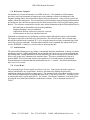
1.3 Microprocessor EEPROM
The microprocessor has 512 bytes of EEPROM memory that are preserved even when power is
removed from the unit. The memory is used by Watson Industries to store calibration coefficients,
serial output information, and other operational values described throughout this manual. Many of
these values can be changed by the user to customize performance to requirements. These values can
be changed either through a Watson Industries supplied program or through use of any terminal
program. Commands for changing the first 256 bytes are described in Appendix A, Serial Command
Information. Watson Industries recommends that you save default EEPROM values before changing
any values. Watson Industries provides a printed copy of the EEPROM map as well as a copy on disk
with the Watson software programs.
2.0 Theory of Operation
2.1 Gyros and Angle Outputs
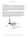
The Watson rate gyro and attitude system incorporates a balance of time constants and error limits to
reduce the effects of dynamic motion, and, at the same time, maintain responsiveness and accuracy .
The correction systems, which all attitude systems use, also allow errors from the forces on a
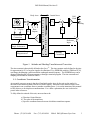
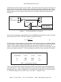
maneuvering aircraft to enter the system. The correction system is shown in Figure 1. Integral to the
correction system are the coordinate transformations used to translate information from body axes to
inertial axes.
The angular rate gyro outputs are compensated outputs which reflect the output of the gyro minus
estimated biases. These rate outputs are shown in Figure 1.
The angular system is essentially second order and each individual axis (Roll, Pitch, Heading), has
approximately (for a single axis of motion) the following La Place response to inputs:
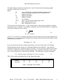
Gyro Response =
K • Rate • s
s + 2ζω n + ω n
2
(1)
and the following general response to reference inputs:
K •Response•( G1 F • s • +ω n 2 )
Gyro Response =
s2 + 2ζω n + ω n 2
(2)
For those versed in frequency response, you will note that the output will eventually return to the
reference value. For example, a short-term bias change will cause the angle output to respond.
However, this will generate an error signal which will change the system to compensate for this bias.
Therefore, the system is self-compensating for errors in the rate sensor.
A disadvantage of the system is that errors in the angle reference will affect the angular rate and angle
output. For example, a lateral or forward acceleration will cause errors in the pendulum reference
signal. If these signals are significant compared to the system Time Constant, noticeable errors will
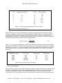
be generated. Please refer to Table 1 for a complete list of appropriate time constants.
Phone: (715) 839-0628
Fax: (715) 839-8248
EMail: [email protected]
2