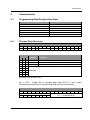
1
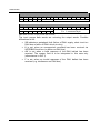
Communication Input process data word IN1 15 14 13 12 11 10 9 8 SB K AW F TB command 7 6 7 6 5 4 3 answer 2 1 0 5 4 3 2 1 S = 0: data byte S = 1: command byte 0 Table 4.2.4: Structure of input process data word IN1 Input process data word IN2 15 14 Y A 13 12 11 10 address byte A A A A 9 8 A S Table 4.2.5: Structure of input process data word IN2 The input proces data words are mirroring the output words. Possible differences at IN1: SB indicates a peripheral fault (failure of DALI supply, short circuit on DALI bus or failure of DALI driver circuitry) K is set, when an unsupported command has been received via INTERBUS local bus (no action on DALI bus) AW is set, when a valid response of the DALI ballast has been received. The answer field is to be interpreted in this case only (otherwise as in OUT1) F is set, when an invalid response of the DALI ballast has been received (e.g. interference on DALI bus) 12 ILT DALI