1
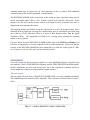
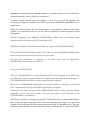
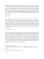
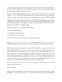
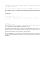
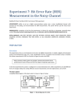
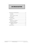
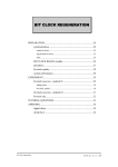
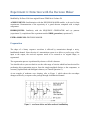
Experiment 6: Detection with the Decision Maker
Modified by Dr Peter Vial from original Emona TIMS lab in Volume D1
ACHIEVEMENTS: familiarisation with the DECISION MAKER module, to be used in later
experiments. Demonstration of the superiority of a gated detector compared with a simple
comparator.
PREREQUISTES: familiarity with the SEQUENCE GENERATOR and eye patterns
(experiment 5); completion of the experiment entitled PRBS generation (experiment 3).
EXTRA MODULES: DECISION MAKER.
Preparation
The shape of a binary sequence waveform is affected by transmission through a noisy,
bandlimited channel. Since the aim of a transmission system is to deliver a perfect copy of the
input to the output, the received sequence needs to be restored to its original shape, or
regenerated.
The regeneration process is performed by what we will call a detector.
You should refer to your text book to see the wide range of circuits which has been devised for
performing this regeneration process, from the simple amplitude limiter, or the comparator, to
extremely sophisticated and intelligent schemes (see Tutorial Question 3).
As an example of moderate wave shaping, refer to Figure 1, which shows the waveshape
changes suffered by a sequence after passage through a bandlimited channel.
If the bandlimited bipolar output waveform of Figure 1 is connected to a comparator, whose
reference is zero volts, then the output will be HI (say +V volt) whilst the waveform is above
zero volts, and LO (say -V volt) when it is below. Visual inspection leads us to believe that it is
unlikely the comparator would make any mistakes. Examination of the eye pattern of the same
waveform would confirm this.
If there was noise, and perhaps further bandlimiting, the comparator would eventually start to
fail. But other, more sophisticated circuits, operating on the same waveform, might still succeed
in regenerating a perfect copy of the original. To be fair to the comparator, it is competent to
decide whether the signal is above (a HI), or below (a LO) a reference. Provided the signal-tonoise ratio (SNR) is not too low then this will be during the HI and LO bits. As the SNR reduces
the comparator output may not match favourably the input, especially as regards pulse width.
Finally its performance as a detector will deteriorate, and extra pulses (or ‘bits’) will appear, as
indicated in Figure 2 below. But note that it is still operating faithfully as a comparator.
Additional circuitry, using the bit clock as a guide, could be implemented to restore the bit width
of the regenerated sequence. This, and more, has been done with the TIMS DECISION
MAKER.
The DECISION MAKER is fed a copy of the corrupted sequence, and also a copy of the bit
clock. It examines the incoming sequence at a specified instant within each bit period. This best
sampling instant may be chosen by you, after inspection of the eye pattern. With additional
external circuitry, this could be automated, or made adaptive.
The DECISION MAKER makes its decision at the instant you have specified within each bit
period, and outputs either a HI or a LO. It makes each HI or LO last for a bit period. It also
outputs a new bit clock, shifted in time relative to the input bit clock, so that the new clock is
aligned with the regenerated bit stream.
The sampling instant, specified by you in this experiment, is set by a front panel control, and is
indicated on the oscilloscope waveform by a high intensity spot (or a shadowed spot when using
one of the two T2445 Tektronics CROs or a series of short duration pulses from the digital
Tektronics CROs). The appropriate waveform to be viewing, when selecting the sampling
instant, is the eye pattern.
For more details about the DECISION MAKER module refer to the TIMS User Manual. You
will have an opportunity to become acquainted with it in this experiment. Please note that the
circuitry of the DECISION MAKER has been optimised for a clock rate in the region of 2 kHz,
so it is unwise to use it at clock rates too far removed from this.
EXPERIMENT
You will examine the decision process applied to a noisy bandlimited bipolar waveform using
two methods: a basic COMPARATOR (ungated), and the TIMS DECISION MAKER module.
In later experiments you will count actual errors, but in this experiment evaluation will be by
visual comparison of the device output and the original sequence.
The test signal
The test signal will come from a SEQUENCE GENERATOR via a noisy, bandlimited channel.
The bandlimiting of the channel will be adjustable. This is illustrated in block form in Figure 3
below.
A model of the block diagram of Figure 3 is shown in Figure 4 below. It uses the macro
CHANNEL MODEL module (from experiment 2).
The macro CHANNEL MODEL module was introduced in the experiment entitled The noisy
channel model (experiment 2 from Emona TIMS Volume D1). It is used for inserting noise,
bandlimiting, and adjusting signal levels. As a reminder the model is reproduced here as Figure
5. To provide an adjustable bandwidth, it uses the TUNEABLE LPF as the bandlimiting module.
Signal regeneration
First patch up the complete system, according to the block diagram of Figure 3, shown modelled
in Figure 4.
Note that: for selecting the best sampling instant the eye pattern is preferred. The oscilloscope is
triggered externally by the bit clock (see experiment 5).
To check, visually, that the recovered sequence is error free, you need the snapshot. The
oscilloscope is triggered externally by the SYNC pulse of the SEQUENCE GENERATOR (see
experiment 5).
Ideally, for visual evaluation, the first of these requires a long sequence, and the second a short
sequence. For convenience, however, you may find it acceptable to use short sequence for both
observations.
T1 before plugging in the SEQUENCE GENERATOR module select the minimum length
sequence with the on-board switch SW2 (both toggles UP).
T2 model the complete system illustrated in Figure 4, except for the DECISION MAKER.
T3 set the AUDIO OSCILLATOR to about 2 kHz. This will suit the DECISION MAKER, which
has been designed for operation with clock rates of this order.
T4 ensure the oscilloscope is triggering on the SYNC signal from the SEQUENCE
GENERATOR. Check the sequence on CH1-A.
Using the COMPARATOR
T5 set the TUNEABLE LPF to its widest bandwidth (select a mid-range gain for the TLPF using
the GAIN knob). Check the signal on CH1-B is roughly of the same shape as shown in Figure 1.
The COMPARATOR should have no trouble regenerating this sequence.
T6 check the COMPARATOR output against the original sequence by looking at CH1-A and
CH2-A simultaneously. Satisfy yourself that regeneration is acceptable.
T7 now carry out some observations of the COMPARATOR output as either or both the channel
bandwidth is varied and noise is added. Get some appreciation of the limitations of the
COMPARATOR as a regenerator.
The best way to do this is to change the gain of the TLPF (while still set on largest bandwidth) so
that you drop the gain to the point where errors are occurring at the output. This also means
keeping a close look at the DC offset coming from the noise (see DC threshold below). The noise
generator module should be on maximum noise setting (+22dB) and the ‘g’ input of the INPUT
ADDER set to maximum (fully clockwise). Observe the effect as you drop the gain down to the
point where errors start to occur at the output of the COMPARATOR. Try using the RUN/STOP
button on the Digital Oscilloscope to compare the output of the COMPARATOR and the input
bit stream. At the point where there are no errors being made then start lowering the bandwidth
of the TLPF and observe the effect of bandlimiting the channel. Repeat for when some errors are
occurring when the filter is on the widest bandwidth. Repeat, again, for larger gains on the TLPF.
Keep an eye on the DC offsets to ensure that the system is not suffering from drift (see DC
threshold below).
Signal levels
Some mention was made above (in T7) about the signal levels at some of the interfaces,
especially that of the gain of the TLPF and the amplitude of the signal relative to the noise (we
were using the largest noise sources possible) at the input to the COMPARATOR. You should be
experienced enough now to realise how important these are. Although this may seem to be a
digital-style experiment, most of the modules are processing analog-level signals. So the signal
levels at their (yellow) interfaces should be adjusted appropriately. That is, they should be at
about the TIMS ANALOG REFERENCE LEVEL, or 4 volt peak-to-peak. Check back that this
was achieved.
DC threshold
In T7 you should also have investigated the purpose of the DC threshold adjustment provided in
the CHANNEL MODEL. You probably did this by slowly reducing the channel output
amplitude, whilst monitoring the COMPARATOR output. Eventually, as the signal amplitude is
progressively decreased, the COMPARATOR output will be all HI or all LO. Fine adjustment of
the DC level from the channel (as suggested in T7 you may have done this by setting the gain ‘g’
of the OUTPUT ADDER to some small, finite value, and used the VARIABLE DC front panel
control to adjust the voltage so its centred around 0 Volts; allowing for a finer adjustment ) will
re-position the sequence with respect to the COMPARATOR reference level (nominally zero, or
ground) and allow operation for even smaller input levels.
Using the DECISION MAKER:
T8 read about the DECISION MAKER module in the TIMS User Manual. Before plugging it in,
ensure that:
a) the on-board switch SW2 is switched to ‘INT’
b) the ‘NRZ-L’ waveform is selected with on-board switch SW1 (upper rear of board). This
configures the DECISION MAKER to accept bipolar non-return-to-zero waveforms, as you have
from the analog output of the SEQUENCE GENERATOR.
T9 to display an eye diagram trigger on the CLK input of the SEQUENCE GENERATOR (TTL
output of AUDIO OSCILLATOR) for the oscilloscope, and connect channel 1 to the output of the
OUTPUT ADDER which will be the input to the DECISION MAKER module in T10. Adjust the
oscilloscope to display an eye pattern (you may wish to change the AUDIO OSCILLATOR
frequency to 8kHz, and select a time scale of about 10 micro seconds to see a better eye pattern
on the T2445 oscilloscope (if using digital oscilloscope connect channel 2 to the BNC output of
the decision maker and look at the pulse train) and then wind it back to 2kHz and change the
time scale appropriately; if finding it difficult further on you may wish to try 8kHz again and
setup the system for that and then go back to 2kHz with minor adjustments).
T10 patch the DECISION MAKER into the system, including the Z-MOD connection to the
oscilloscope on the back panel of the T2445. If using the Digital oscilloscope connect channel 2
to the BNC output (Z-MOD output) of the DECISION MAKER card.
T11 rotate the front panel DECISION POINT control knob of the DECISION MAKER. There
should be a highlighted point moving across both oscilloscope traces (or in the case of the pulse
train on channel 2 for the digital oscilloscope you should see the pulses move in time position or
phase relative to channel 1). If the dark spot (actually a dark line) cannot be seen (using the
T2445 oscilloscope only), try varying the oscilloscope intensity control. If still no dark spot, seek
help from your Laboratory demonstrator. As a last resort (!) refer to the TIMS User Manual
and the oscilloscope User Manual. There are settings on the DECISION MAKER circuit board
to suit most oscilloscopes, and once set (by the Laboratory Manager) they require no further
adjustment. You should ideally do this at 2kHz but you may also try 8kHz as long as you return
to 2kHz by step T12.
note: make sure a TTL bit clock is connected to B.CLK in.
T12 locate the high intensity dark spot on the oscilloscope display if using the T2445 (or the
relative location of the train of pulses from the Z-MOD output on the DECISION MAKER if
using the digital Oscilloscope). This shows the sampling instant.
T13 adjust the front panel control of the DECISION MAKER so that the sampling instant is
positioned at the best decision point within the bit period; ie, where the vertical eye opening is
greatest.
T14 the regenerated sequence will be displayed on CH2-B. Compare it with the input sequence
on CH1-A. There will, of course, be a time offset between the two, due to the delay introduced
by the filter, and the regeneration process itself.
Note that the DECISION MAKER provides a new bit clock, aligned with the regenerated
sequence. This is essential for later processing of the regenerated sequence (eg, by the error
counter - see later). You will now make some more demanding tests of the DECISION MAKER.
Changing from one display to the other involves a little more than changing the connection to the
ext trig of the oscilloscope, as generally the sweep speed needs some slight adjustment. Ideally,
also, the snapshot needs a short sequence, and the eye a long sequence. But for these tests a
short sequence should be acceptable for both.
What you will have to do, each time you make a test, is:
1. lower the bandwidth a little
2. re-position the sampling instant
3. check the sequences for equality
You can develop your own visual scheme for comparing sequences.
T15 now carry out some observations of the DECISION MAKER output, as you did for the
COMPARATOR output, as either or both the channel bandwidth is varied and noise is added.
T16 Get some idea of the performance of the DECISION MAKER, as compared with that of the
simple COMPARATOR, as a regenerator. To do this connect both devices back into the system.
Do the comparison at 2kHz, adjust the system so that the output of the COMPARATOR starts to
make mistakes (with widest bandwidth from the TLPF and adjust the gain of the TLPF), now
have a look at the output of the DECISION MAKER. You should, probably, observe that the
DECISION MAKER is still not providing quite as many errors as the COMPARATOR. Why do
you think that this is the case? Think about how often the COMPARATOR makes a decision
compared to the DECISION MAKER per bit period(see Tutorial Question 1).
T17 Try lowering the bandwidth of the system by changing the TUNE knob of the TLPF and
compare the two techniques.
Error counting
During the above observations you may have been saying ‘there must be a better way to judge
performance ?’ And, of course, there is ! A visual check for errors provides a quick method for
comparing short sequences, but it is a qualitative check only; something quantitative is then
required for serious measurements.
More systematic methods are introduced in the experiment entitled BER measurement in the
noisy channel in Volume D2 - Further and Advanced Digital Experiments (which is experiment
7).
Summing up
The DECISION MAKER module will be used in many more experiments, so it is important to
have a good understanding of its capabilities and limitations. Make sure you read its data sheet.
TUTORIAL Questions
Q1 explain why a strobed decision process can be expected to result in a lower incidence of
errors, compared to an ungated (instantaneous) comparator. (see T16)
Q2 familiarize yourself with the terms ‘timing jitter’ and ‘baseline wander’. Explain, via the eye
pattern, how these affect the satisfactory operation of the detection device (hint: look at the
introduction for experiment 4 on line coding, under ‘why line coding?’).
Q3 in this experiment we use a ‘stolen clock’ to generate the strobe clock at the receiver. Refer
to your text book and describe the essence of a clock recovery process in a commercial
application.