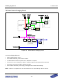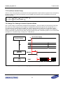
1
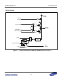
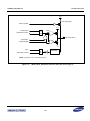
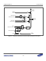
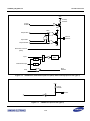
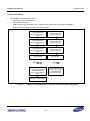
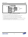
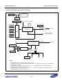
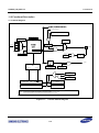
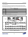
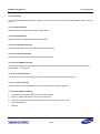
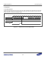
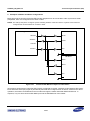
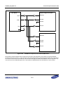
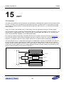
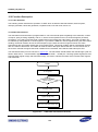
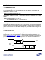
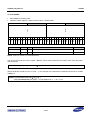
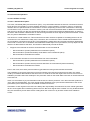
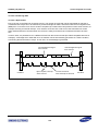
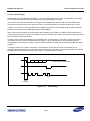
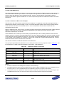
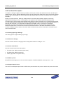
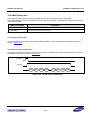
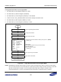
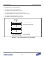
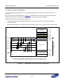
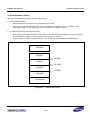
S3FN60D_UM_REV1.30 15 UART 15.2 Function Description 15.2.1 Uart Operation The following section describe the operation of UART which include the data transmission, data reception, interrupt generation, baud-rate generation, loopback mode, infra-red mode, and so on. 15.2.2 Data Transmission The data frame for transmission is programmable. It can have several options regarding to the data size, number of stop bit, parity checking capability, and so on, which can be specified in the Line Control Register (ULCON). Sometimes, you need to send the break condition during the sending the UART frame. The break condition can be realized by writing SBS bit in UCON registers. If you write the SBS bit in UCON register during the UART frame sending, the break condition forces the serial output to logic 0 state at least for longer time than one frame transmission after successful sending the current UART frame. This break condition will be automatically cleared after one frame of break time. The UART will send the frame data again after break time. On the receive side, if the receive controller recognize the break condition from Transmitter, there will be break interrupt to CPU. The data transmission process is shown in Figure 15-2. The transmitter should transfer the data through a path as follows: data source transmit buffer register transmit shifter UTXD pins. Two flags (status signals) such as transmit buffer register empty and transmitter empty, are used to indicate the status of the transmit buffer register and transmitter. START UBRDIVn, ULCONn, UCONn is conf igured Transmit buf f er register empty ? N Y Transf er the data to transmit shif ter Set the transmit buf f er register empty f lag Af ter shif t out last stop bit, Set the transmitter empty f lag Figure 15-2 UART Data Transmission Process 15-2