1
S3FN60D_UM_REV1.30
15
15 UART
UART
15.1 Overview
The UART (Universal Asynchronous Receiver and Transmitter) in S3FN60D can support one asynchronous serial
I/O ports. The UART can be operated by the interrupt-based mode or a DMA request. In other words, the UART
can generate an interrupt request or a DMA request to prepare the data to be sent, or to store the received data
into the memory.
UART can operate in DMA-based mode. In other words, UART can generate an interrupt or a DMA request.
The functionality of UART includes the programmable baud-rate, frame format suitable for infra-red (IrDA ver. 1.0)
transmit/receive, programmable number of stop bit insertion, programmable data width of 5, 6, 7 and 8-bit, and
parity checking/attaching capability of received/transmitted data.
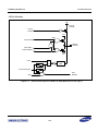
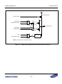
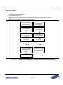
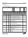
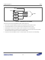
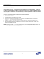
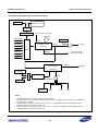
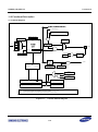
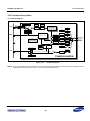
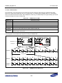
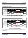
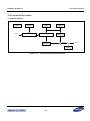
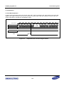
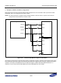
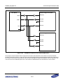
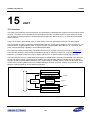
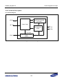
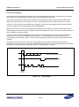
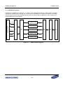
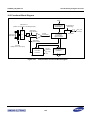
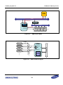
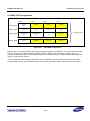
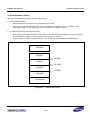
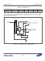
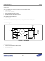
The UART has a baud-rate generator, transmitter/receiver block and their control unit as shown in Figure 15-1.
The baud-rate generator can generate the suitable baud rate for UART by using PCLK. To generate the proper
baud rate, you should configure the proper division rate of PCLK in special register in baud rate generator.
The transmitter and receiver contain data buffer register and data shifters. Data to be transmitted is first written to
the transmit buffer register (UTXH) and then copied to the transmit shifter where it is shifted out by the transmit
data pin (UTXD). Received data is shifted in by the receive data pin (URXD), and is copied from the shifter to the
receive buffer register (URXH) when one complete data byte has been received. Controls are provided for mode
selection, status monitoring, and for interrupt generation.
Transmi tter
Transmi t Buffer
Transmi t Shi fter
Control
Uni t
Baud-rate
Generator
Recei ve Shi fter
Recei ve Buffer
Recei ver
Figure 15-1
UART Block Diagram
15-1
UTXD
PCLK
URXD