1
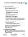
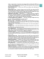
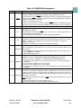
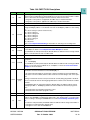
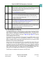
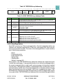
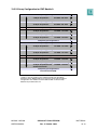
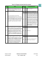
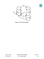
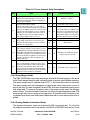
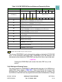
Table 19-11 Erase Interlock State Descriptions
State
Next
State
Mode
Transition Requirement
Normal Operation:
S1
S2
S3
S4
S5
Normal array reads and register accesses. The
Block protect information and pulse width timing
control can be modified.
S2
T2
Write PE = 1, SES = 1.
Erase Hardware Interlock Write:
S1
T1
Write SES = 0 or a master reset
Normal read operation still occurs. The CMF accepts the erase hardware interlock write. This write
may be to any CMF array location. Accesses to the
registers are normal register accesses. A write to
CMFCTL can not set EHV at this time. A write to
the register is not an erase hardware interlock
write, and the CMF remains in state S2.
Hardware Interlock
S3
T3
High Voltage Write Enable
S1
T6
Write SES = 0 or a master reset
Erase margin reads will occur. Accesses to the
registers are normal register accesses. A write to
CMFCTL can change EHV.
S4
T4
Write EHV=1
Erase Operation:
S1
T7
Master reset
High voltage is applied to the array blocks to erase
the CMF bit cells. The pulse width timer is active if
SCLKR[0:2] ≠ 0, and HVS can be polled to time the
erase pulse. During the erase operation, the array
does not respond to any address. Accesses to the
registers are allowed. A write to CMFCTL can
change EHV only.
S5
T5
Write EHV = 0, disable the internal
memory map or a soft reset
Erase Margin Read Operation:
S4
T8
Write EHV = 1
These reads determine whether the state of the
bits in the selected blocks needs further modification by the erase operation. Once a bit is fully
erased it returns one when read. All words within
the blocks being erased must be read to determine
whether the erase operation is completed.
S1
T9
Write SES = 0 or a master reset
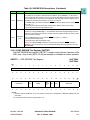
A successful write to any CMF array location is the erase interlock write. If the
write is to a register the erase hardware interlock write has not been done
and the CMF will remain in state S2.
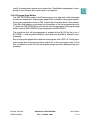
19.6.2 Erase Margin Reads
The CMF EEPROM provides an erase margin read with electrical margin for the erase
state. Erase margin reads provide sufficient margin to ensure specified data retention.
The erase margin read is enabled when SES = 1 and the erase write has occurred.
The erase margin read and subsequent on-page erase verify reads return a zero for
any bit that has not been completely erased. Bits that have completed erasing return
one when read. To increase the access time of the erase margin read, the off-page
access time is 16 clocks instead of the usual two clock off-page read access time. The
erase margin read occurs during an off-page read. All locations within the block(s) being erased must return one when read to determine that no more erase pulses are required.
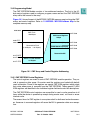
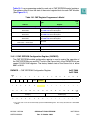
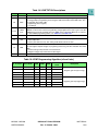
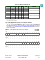
19.6.3 Erasing Shadow Information Words
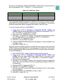
The shadow information words are erased with CMF array block zero. To verify that
the shadow information words are erased, the SIE bit in CMFMCR must be set to one
MPC555 / MPC556
CDR MoneT FLASH EEPROM
USER’S MANUAL
Rev. 15 October 2000
MOTOROLA
19-26