1
3. Operation
3. Operation
3.1. Operation Mode and Input/Output
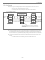
There are two ways to input signals to the Driver Unit CN2: control Input/Output connector and
remote input by the CN6: interface connector. There are two operation modes to receive those
inputs exclusively.
◊ Fieldbus mode: The prompt of the Handy Terminal is “#”.
◊ Maintenance mode: The prompt of the Handy Terminal is “:”.
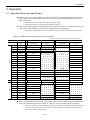
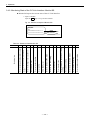
The operation mode and format of Inpt/Output are shown in the Table 3-1 “Operation mode and
composition of Input/Output” (The function assignment is the shipping set).
◊ The operative Inputs/Outputs of each operation mode are shown in the bold line boxes below.
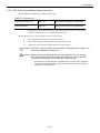
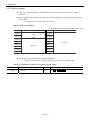
Table 3-1: Operation mode and composition of Inputs/Outputs
m: A register number derived from the top station number
Outpu
Input
Input/Output
Signal
Port code
code
Fieldbus mode
Maintenance mode
Remote
CN2
Input/Output
Pin No.
Remote
Input/Output
CN2
Pin No.
RYm0
3
RYm0
3
PI0
EMST
PI1
ACLR
RYm1
4
RYm1
4
PI2
PI3
OTP
OTM
RYm2
RYm3
5
6
RYm2
RYm3
5
6
PI4
SVON
RYm4
‒
RYm4
‒
PI5
RUN
RYm5
‒
RYm5
‒
PI6
STP
RYm6
‒
RYm6
‒
PI7
PRG0
RYm7
‒
RYm7
‒
PI8
PRG1
RYm8
‒
RYm8
‒
PI9
PRG2
RYm9
‒
RYm9
‒
PI10
PRG3
RYmA
RYmA
‒
PI11
PRG4
RYmB
PI12
PRG5
RYmC
PI13
PRG6
RYmD
PI14
PRG7
RYmE
PI15
JOG
RYmF
‒
PI16
DIR
RY(m+1)0
PO0
DRDY
PO1
WRN
‒
RYmB
‒
RYmC
‒
RYmD
‒
RYmE
‒
RYmF
‒
‒
RY(m+1)0
‒
RXm0
8
RXm0
8
RXm1
‒
RXm1
‒
RXm2
‒
‒
PO2
OTPA
RXm2
‒
PO3
OTMA
RXm3
‒
RXm3
‒
PO4
SVST
RXm4
‒
RXm4
‒
RXm5
‒
PO5
BUSY
RXm5
‒
PO6
IPOS
RXm6
‒
RXm6
‒
PO7
NEARA
RXm7
‒
RXm7
‒
In case of the fieldbus mode, take the input signals from the CN6 connector. For the maintenance
mode, take them through the CN2 connector. However, there are following two exceptions.
◊ The port assigned to the Input EMST (Emergency stop) regards the Input of both CN2 and CN6
connectors as the “Emergency stop” signal. This means that the system gets in the emergency
stop state by either one of the inputs.
— 3-1 —