1
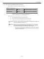
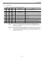
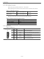
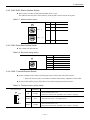
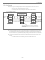
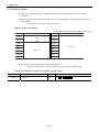
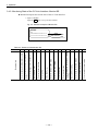
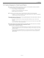
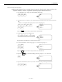
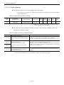
MEGATORQUE® MOTOR SYSTEM
User’s Manual
(EDC Driver Unit CC-Link Option)
M-E099DC0C2-157
Document Number: C20157-02
Limited Warranty
NSK Ltd. warrants its products to be free from defects in material and/or workmanship which NSK
Ltd. is notified of in writing within, which comes first, one (1) year of shipment or 2400 total
operation hours. NSK Ltd., at its option, and with transportation charges prepaid by the claimant,
will repair or replace any product which has been proved to the satisfaction of NSK Ltd. to have a
defect in material and/or workmanship.
This warranty is the sole and exclusive remedy available, and under no circumstances shall NSK
Ltd. be liable for any consequential damages, loss of profits and/or personal injury as a result of
claim arising under this limited warranty. NSK Ltd. makes no other warranty express or implied,
and disclaims any warranties for fitness for a particular purpose or merchantability.
Copyright 2011 by NSK Ltd., Tokyo, Japan
All rights reserved.
No part of this publication may be reproduced in any
form or by any means without permission in writing
from NSK Ltd.
NSK Ltd. reserves the right to make changes to any
products herein to improve reliability, function or design
without prior notice and without any obligation.
NSK Ltd. does not assume any liability arising out of the
application or use of any product described herein;
neither does it convey any license under its present
patent nor the rights of others.
Patents issued and patents pending.
“MEGATORQUE” is a registered trademark of NSK Ltd. in
Japan and that of NSK Corp. in the United States of
America.
Contents
1. Introduction -----------------------------------1-1
4. Alarm and Warning --------------------------4-1
1.1.Notes for Users -------------------------------------------1-2
1.1.1. Notes for Safety ------------------------------------1-2
4.1. Cause and Rmedy of Alarm and Remedy -------- 4-1
4.1.1. C4: Fieldbus Error -------------------------------- 4-1
4.1.2. C5: Fieldbus Warning -------------------------- 4-2
2. Specifications ---------------------------------2-1
2.1. General Specifications-----------------------------------2-1
2.2. Specifications of Hardware Interface-----------------2-1
2.2.1. External Dimensions ------------------------------2-1
2.2.2. CN2: Control Input/Output Signal Connector
2.2.2.1. CN2 Pin-Out --------------------------------2-4
2.2.2.2. CN2 Signal List ----------------------------2-5
2.2.3. CN6: Interface Connector ----------------------2-6
2.2.3.1. C6 Pin-Out ----------------------------------2-6
2.2.4. SW1 • SW2: Station Number Switch --------2-7
2.2.5. SW3: Baud Rate Setting Switch --------------2-7
2.2.6. SW4: Terminal Resistor Switch ----------------2-7
2.2.7. LED Status Monitor (SD, RD, RUN and ERR)
----------------------------------------------------------2-8
2.2.8. Wiring Example-------------------------------------2-9
2.3. Software Interface Specification ------------------- 2-10
2.3.1. Remote Input/Output---------------------------- 2-10
2.3.2. Remote Register --------------------------------- 2-12
3. Operation -------------------------------------3-1
3.1. Operation Mode and Input/Output -------------------3-1
3.2. Change of Operation Mode ---------------------------3-2
3.3. Servo-on in the Maintenance Mode -----------------3-2
3.4. Monitoring Control Input/Output ---------------------3-4
3.4.1. Monitoring the State of Remote Inputs/Outputs:
Monitor IO4 ------------------------------------------3-5
3.4.2. Monitoring State of the CC-Link Interface:
Monitor BS--------------------------------------------3-6
3.5. Function Assignment of Control Inputs/Outputs---3-7
3.5.1. Function of Conrol Inputs ------------------------3-8
3.5.2. Function of Control Outputs ----------------- 3-10
3.5.3. Editing Coptrol Inputs/Outputs -------------- 3-12
3.5.3.1. Editing Contorl Inputs ------------------ 3-12
3.5.3.2. Editing Control Outputs ---------------- 3-15
3.5.3.3. Masking the Function of Control
Inputs/Outputs --------------------------- 3-18
3.5.3.4. Forcible Change in Setting Control
Output Port Function --------------------- 3-19
—i—
(Blank Page)
— ii —
1. Introduction
1. Introduction
This manual describes an option of the Megatorque Motor System that consists of the EDC
Driver Unit CC-Link option. Please refer to the user’s manual of the Megatorque Motor System
(EDC Driver Unit System) for other details.
Connection of the optional EDC Driver Unit to the CC-Link network will make you utilize its
control Input/Output functions through the master station.
For your safety, please be sure to read the user’s manual thoroughly before operating the
Megatorque Motor System.
1.1. Notes for Users
1.1.1. Notes for Safety
For your safety, you should read this manual thoroughly and understand the contents before
operating the Megatorque Motor System.
The following notices are added to give particular emphasis on the safety precautions in this
manual.
! Danger : A matter that might cause serious injuries.
! Warning : A matter that might result in injuries.
! Caution : A matter that might result in the breakdown of equipment into which the
Motor is installed or the break down of the mechanism surrounding the
Motor.
— 1-1 —
1. Introduction
(Blank Page)
— 1-2 —
2. Specification
2. Specifications
2.1. General Specifications
Table 2-1: General specifications
Item
Protocol
Number of slave stations
(Type of station)
Number of addressable
remote input ports
Number of addressable
remote output ports
Remote register output
Description
CC–Link Ver.1.10
2 Remote device stations
16 ports are available for any function
assignment
7 ports are available for any function
8
assignment
17
2 words Enables to configure the contents of output
2.2. Specifications of Hardware Interface
2.2.1. External Dimensions
Fig. 2-1: EDC Driver Unit compatible with CC-Link Network
( Motor type: PS1006, PS1012, PS1018, PS3015 and PS3030)
— 2-1 —
2. Specification
Fig. 2-2: EDC Driver Unit compatible with CC-Link Network
(Motor type: PS3060 and PS3090)
— 2-2 —
2. Specification
2.2.2. CN2: Control Input/Output Signal Connector
The table below shows the connectors for CN2.
Table 2-2: Connector list
Connector of Driver Unit
DDK Ltd.
DHF-RAA10-233NB-FA or equivalent
Mating connector
DDK Ltd
DHF-PDA10-3-A01-FA or equivalent
◊ An optional cable set (M-E011DCCN1-001) with the mating connector to the CN2 I/O
connector of the Driver Unit is available (Sold separately).
The followings are wiring precautions for the connector CN2.
1)
Use a shielded cable for wiring of the CN2 connector.
2)
These cables should be laid separately from the main power line.
3)
Connect the one end of the shielded cable to the frame ground.
! Caution : Check for a wiring mistake in the polarity of external power supply, and
a shorting between connector pins.
! Caution : Never connect the idle pins that are insntructed as “Do not connect.”
Do not make them idle at the master controller (PLC, etc) side, after
you have connected all pins at the CN2 connector side.
• Connection of an idle pin that is instructed not to connect may make the
Driver Unit easily affected by external noise, and thus likely causing its
malfunction or breakdown.
— 2-3 —
2. Specification
2.2.2.1. CN2 Pin-Out
Figure 2-3 below shows the shipping set of the pin-out arrangement of the CN2 connector.
You may change the function assignment of each signal port.
(Except some ports that are dedicated to a certain function)
◊ Change to an extended capability port.
◊ Transfer an assigned function to other port.
◊ Mask the function of unused port.
The each port of the CN2 connector is assigned to the same port name as the remote
Input/Output of the CN6 interface connector, and the ports of both connectors are corresponsing
each other.
! Caution : A change of function assignment of a port of the CN2 connector forces the
function change to the remote Output/Input of the corresponding port.
Fig. 2.3: CN2 pin-out
1
DC24
General Input
EMST : Emergency stop
ACLR : Alarm clear
OTP : Travel limit, + direction
OTM : Travel limit, - direction
SVON : Servo ON
RUN : Positioning start
STP : Stop
PRG0 - 7: Internal program chanel
selection 0 to 7
JOG : Jogging
DIR
: Jogging direction
HLD : Hold
ORD : Velocity override
IOFF : Integration OFF
HOS
: Home Return start
HLS
: Home position limit
2
-
3
PI0
EMST
4
PI1
(ACLR)
5
PI2
(OTP)
6
PI3
(OTM)
7
-
8
PO0
(DRDY)
9
-
Input dedicated to the safety functions
EMST: Emargency stop
Output dedicated to the safety functions
DRDY: Driver Unit ready
NRM :Normal
10
COM
Note: Functions in brackets is the shipping set.
: The pins with hyphones “-“ are prophibited
connection.
PI0 and PO0 ports are dedicated to the safety function Input and Output. They have following
restrictions respectively.
◊ You cannot change the function of the port PI0 (Pin number 3: Input EMST
(Emergency stop)). You may only set the input port and the stability timer to it.
◊ You can only exchange the function of the PO0(Pin number 8: Output DRDY (Drive
Unit ready) with the function Output NRM (Normal). You cannot set the output logic
and the stability timer to it.
— 2-4 —
2. Specification
2.2.2.2. CN2 Signal List
Table 2-3: Signal name and function (shipping set)
Pin
No.
Port
code
Signal
code
Contact
logic
1
-
DC24
--
2
-
-
Normaly
closed
Normaly
open
Normaly
closed
Normaly
closed
Signal function
24 VDC external power
supply
Do not connect
Emergency stop
3
PI0
EMST
4
PI1
ACLR
5
PI2
OTP
6
PI3
OTM
7
-
-
-
Do not connect
8
PO0
DRDY
Positive
Driver Unit ready
9
-
COM
-
Do not connect
Output signal COMMON
10
Alarm clear
Travel limit, + direction
Travel limit, - direction
Function
External power supply for input signal
Interrupts the positioning and stops with the dynamic
brake
Clears warning
If OTP input goes active, the Motor servo is locked in
the CW only
If OTM input goes active, the Motor servo is locked in
the CCW only
Reports that the Motor is ready to rotate (Those pins
open when Motor is not ready, or an alarm occurs)
Common for output signal
! Caution : Be sure to follow the operation manual when your Megatorque Motor
System is a custom-made version and the function of Input/Output signals
are specially arranged.
! Caution : Never connect the pins indicated as “Do not connect” Be sure to connect
these pins of the master controller (PLC, etc) side after you have connected
all pins of the CN2 connector. Otherwise, it may result in a malfunction or
breakdown of the system.
— 2-5 —
2. Specification
2.2.3. CN6: Interface Connector
The CN6 connector interfaces with the CC-Link network.
The followings are the reference for the connectors that are used for the CN6 connector.
Table 2-4: CN6 mating connectors
Connector, Driver Unit side
Phoenix Contact Gmbh, & Co.
MSTB2,5/5-GF-5,08AU or
equivalent
Mating connector
Phoenix Contact Gmbh, & Co.
MSTB2,5/5-STF-5,08AU or
equivalent
Table 2-5 below shows the reference data for the mating connectors.
Table 2-5: Reference data of the mating connector
Item
Cable to be used (single connection)
Cable to be used (double connection)
Removed coat length
Machine screws to be used
Tightning torque
Specification
0.2 to 2.5 [mm2] (twisted) (AWG24 to 12)
0.2 to 1.5 [mm2] (twisted)
7 [mm]
M3
0.5 to 0.6 [N·m]
2.2.3.1. CN6 Pin-Out
Table 2-6: CN6 pin-out
Top of the Driver Unit
5:
4:
3:
2:
DG
DB
DA
SLD
1: FG
Pin
No.
Signal
code
Function
1
FG
Frame ground
2
SLD
Shield
Connect the shielded cable (Frame ground cable)
3
DA
Data A
Connect the data A cable
4
DB
Data B
Connect the data B cable
5
DG
Data ground
— 2-6 —
Description
Connect the frame ground
Connect the data ground cable
2. Specification
2.2.4. SW1•SW2: Station Number Switch
These rotary switches set the station number from 1 to 64.
The SW1sets the tens place of the number, while the SW2 switch sets the ones place.
Table 2-7: Station number switch
5
0
4
3
2
Station number
0
0
(Never set)
0
1
1 (Shipping set)
…
9
SW2
…
8
7
6
SW1
…
D river U nit ’s upp er side
6
4
64
S W 2: ×1
1
8
7
9
6
5
0
S W 1: × 10
1
4
3
2
2.2.5. SW3: Baud Rate Setting Switch
The switch sets the baud rate.
Table 2-8: Baud rate setting switch
Driver Unit’s upper side
SW3
Baud rate[bps]
0
156k
625k
2.5M
5M
10M (Shipping set)
Never set
1
7
9
6
5
4
2
8
3
0
1
3
4
2
5-9
2.2.6. SW4: Terminal Resistor Switch
Set the terminal resistor when connecting the Driver Unit to the end of the network.
◊ Select the resistor value in accordance with the characteristic impedance of the cable.
Be sure to turn off the power of the Driver Unit when setting the terminal resistor.
Table 2-9: Terminal resistor setting switch
SW4
Terminating
resistance
1 30Ω
Up
130 [Ω]
O FF
Neutral
None
Down
110 [Ω]
Driver Unit’s upper side
11 0Ω
Description
• The terminal resistor is on
(When the characteristic impedance of the cable is 130 [Ω])
• The terminal resistor is off (Shipping set)
• The terminal resistor is on
(When the characteristic impedance of the cable is 110 [Ω])
— 2-7 —
2. Specification
2.2.7. LED Status Monitor (SD, RD, RUN and ERR)
The monitor indicates the status of conection and communicatoin with the network.
When the communication status is nomal, the indicators RUN, RD and SD are on, and that of
ERR is off (In some baud rate, the RD and SD indicators seem like blinking).
Table 2-10: LED status monitor
Indicator
Driver Unit’s upper side
Green
RD
RUN
Description
On: In the middle of tarnsmitting data
SD
RD
SD
Color
On: In the middle of receiving data
RUN
On: Executing the data link. The unit is normal
Off: Not linked to the network. Caririer detection NG, Time-Over, Resetting
ERR
On:CRC error, SW1and 2 (Station number) setting error, or SW3 (Baud rate)
setting error
Off: Communicating normally or Resetting hardware
Blinking: The switch setting (SW1, 2 and 3 ) is altered
E RR
Red
Table 2-11: Monitoring pattern
SD
RD
RUN
ERR
Status
✷
●
●
○
Communicating normally
✷
●
●
✷
Communicating normaly, with occasional CRC error
✷
●
●
✷*
Baud rate and/or station number setting are alterd at the time of power
on.
*
LED flickers at intervals of every 0.4 [s]
○
●
●
✷
Transferred data become “CRC Error” and thus unable to responsd
○
●
●
○
No data transmission to the Driver Unit
✷
●
○
✷
Though the polling is responding, the refresh receiving has a CRC error
○
●
○
✷
Cannnot respond as the data to the Driver Unit has a CRC error
✷
●
○
○
The communication link is not active
○
●
○
○
No data sent to the Driver Unit, or impossible to receive the data
○
○
○
○
Impossible to receive the data. Power shutdown, or the hardware is in
the middle of resetting
○
●/○
○
●
Setting error on the baud rate or station number
●: On ✷: Blinking ○: Off
The SD monitor is blinking quickly, and thus it occasionally seemes like as if it is on depending
on the communication state.
— 2-8 —
2. Specification
2.2.8. Wiring Example
Refer to “Figure 2-4: Wiring example” below for wiring the Drive Unit to the CC-Link.
◊ Be sure to use a cable dedicated to the CC-Link.
◊ The wiring order is not necessarily the same order of station numbers.
Fig. 2-4: Wiring example
Remote station
(EDC Driver Unit)
Local station
DA
DA
DA
Terminating
DB
DB
DB
resistor
DG
DG
DG
Master station
Terminating
resistor
SLD
FG
CC-Link dedicated cable
SLD
CC-Link dedicated cable
FG
SLD
FG
When the EDC Driver
Unit is the terminating
unit, the SW4 switch
may be used for the
function of terminating
resistor.
When the grounding terminal of the Driver Unit (Heat sink) is
grounded, grounding of the FG terminal of the CN6 connector
is not necessary.
Connect the shielded wire of the CC-Link dedicated cable to the SLD terminal of CN6 connector.
The SLD terminal is connected to the housing of the Driver Unit through the FG terminal and
thus, the shielded wire is grounded through the gorunding terminal of the Driver Unit (Heatsink).
Connect the terminating resistor between the DA and DB terminal of the both end units of the
network .
◊ The SW4 switch sets the terminating resistor for the EDC Driver Unit.
— 2-9 —
2. Specification
2.3. Software Interface Specification
2.3.1. Remote Input/Output
Table 2-12 “Remote Input/Output” on the next page shows the function of Input/Output of the
CN6 interface connector (Shipping set).
Excluding some ports, you may change the function assignment to the remote Input/Outpu ports.
Please refer to “3.5 Function Assignment of Control Input/Output” for the details of
Input/Output signal logic and the function that can be assigned to each Input/Output port.
◊ Replaces an assigned function with an extended function.
◊ A previously assigned function may be set to other port.
◊ Masks a unused port.
The same port name of the CN2 control I/O connector is assigned to the corresponding port of
the remote I/O connector and the I/O function of each port is also corresponding each other.
! Caution : Pay special attention when changing the function assignment of Remote
Input/Output port because that of the corresponding port of the CN2 signal
connector changes its function also.
— 2-10 —
2. Specification
Table 2-12: Remote Input/Output
Output
Port
code
Signal
code
RXm0
PO0
DRDY
RXm1
PO1
WRN
(m: A register number derived from the top station number)
Input
Port
code
Signal
code
Reports that the Motor is
ready for the operation
RYm0
PI0
EMST
Interrupts the positioning
and stops with the dynamic
brake
Alerts warning.
RYm1
PI1
ACLR
Clears warning
RYm2
PI2
-
Reserved *1
RYm3
PI3
-
Reserved *1
Function
Over travel limit (+) (Soft and
hard ware limit switch)
Over travel limit (-) (Soft and
hard ware limit switch)
Function
RXm2
PO2
OTPA
RXm3
PO3
OTMA
RXm4
PO4
SVST
Reports the state of the servo
RYm4
PI4
SVON
RXm5
PO5
BUSY
Reports the operation state
RYm5
PI5
RUN
Starts the program operation
specified by the PRG input
RXm6
PO6
IPOS
RYm6
PI6
STP
Stops positioning operation
RXm7
PO7
NEARA
RYm7
PI7
PRG0
RXm8
-
-
Reports the conditions in
position error and positioning
Reports that the Motor is
approaching the target position
(Reserved)
RYm8
PI8
PRG1
RXm9
-
-
(Reserved)
RYm9
PI9
PRG2
RXmA
-
-
(Reserved)
RYmA
PI10
PRG3
RXmB
-
-
(Reserved)
RYmB
PI11
PRG4
RYmC
PI12
PRG5
Turns the servo on
A combination of 1 and 0
(ON/OFF) of the“Internal
program channel selection”
selects a channel to be
executed (Channel 0 -255)
RXmC
-
-
(Reserved)
RXmD
-
-
(Reserved)
RYmD
PI13
PRG6
RXmE
-
-
(Reserved)
RYmE
PI14
PRG7
RXmF
-
-
RYmF
PI15
JOG
RX(m+1)0
-
-
RY(m+1)0
PI16
DIR
-
-
-
-
(Reserved)
-
-
-
-
(Reserved)
RX(m+1)1
to
RX(m+2)F
RX(m+3)0
to
RX(m+3)7
(Reserved)
RY(m+1)1
to
RY(m+2)F
RY(m+3)0
to
RY(m+3)7
(Reserved)
(Reserved)
RX(m+3)8
-
RX(m+3)9
-
RX(m+3)A
-
RX(m+3)B
-
RX(m+3)C
to
RX(m+3)F
(Reserved)
-
Flag for processsing an initial data
(Not used)
Flag for “End of initial data setting”
(Not used)
Starts and stops a jog
operation
Specifies the direction of a
jog operation
RY(m+3)8
-
Flag for completion of initial data
processing. (Not used)
RY(m+3)9
-
Flag for initial data setting (Not used)
Flag for positioning state (Not used)
RY(m+3)A
-
Flag for requesting error reset (Not
used)
The remote station is ready
RY(m+3)B
-
-
(Reserved)
RY(m+3)C
to
RY(m+3)F
-
-
(Resrved)
-
(Reserved)
*1: The shipping set of PI2 and PI3 ports is assigned to signals of OTP and OTM respectively. These are the dedicated input signals from
the CN2: control I/O connector. An input from the CC-Link to these OTP and OTM function ports shall become invalid.
The PI0 and PO0 are dedicated ports for the signals fundamental to the safety function. There are
following restrictions respectively.
◊ You cannot change the function EMST(Emaergency stop) assigned to the Port PI0 (RYm0).
◊ The Output DRDY (Driver Unit Ready) assigned to the Port PO0 (RXm0) is only
interchangeable with the function of NRM(Normal).
Refer to “3.5 Function Assignment of Control Input/Output” for the logic of each function.
— 2-11 —
2. Specification
2.3.2. Remote Register
Table 2-13 “Remoto Register” shows the functon of remote register of the CN6 : interface
connector.
Remote register outputs data monitoring, such as a coordinate data, using two words of remote
register RWr.
◊ The data consists of 32 bit integer with the sign.
Table 2-13: Remote Register
m: A register number derived from the top station number
Output
Function
Input
RWrm+0
Monitor data set by the POD parameter
(LSW)
to
(MSW)
RWwm+0
RWrm+1
RWwm+1
RWrm+2
RWwm+2
RWrm+3
RWwm+3
RWrm+4
(Reserved)
RWrm+5
Function
(Reserved)
RWwm+4
RWwm+5
RWrm+6
RWwm+6
RWrm+7
RWwm+7
The output is set by the parameter POD (Polling data).
◊ The parameter POD must accompany the name of monitor that is outputting data.
Table 2-14: Parameter related to the remote register output
Parameter
POD
Function
Polling data
Default
TP
— 2-12 —
Domain
Set POD + Monitor name
2. Specification
The following show an example to output the data of current velocity to the CC-Link.
1) Monitor TV (Current velocity readout) reports the current velocity of the Motor.
Set “Monitor TV” to the parameter POD (Polling data) to output to the CC-Link.
P
2)
O
D
T
V
ENT
#PODTV
#_
Monitor TV reports the current velocity in units of a thousandth of [s -1 ] as described in
the “Megatorque Motor System User’s Manual ( EDC Driver Unit System)”.
◊ The current velocity is given in the units of a thusandth as –5.000 when the Motor is rotating to
the minus direction at the velocity of 5 [S-1].
Fig. 2-5: Description of “Monitor TV” (Megatorque Motor System User’s Manual [EDC Driver Unit System])
3)
The decimal point is abbreviated when outputting to the CC-Link.
When the Motor is rotating at -5.000, -5000 (FFFF EC78h in hexadecimal number)
will be outputted. Table 2-15 below shows an example of the relation between the
register address and the contents of an output.
Table 2-15: Output example of the remote register (When outputting -5000)
m: A register number derived from the top station number
Output
Function
Input
RWrm+0
EC78h
FFFFh
RWwm+0
RWrm+1
RWwm+1
RWrm+2
RWwm+2
RWrm+3
RWwm+3
RWrm+4
RWwm+4
RWrm+5
(Reserved)
Function
RWwm+5
RWrm+6
RWwm+6
RWrm+7
RWwm+7
— 2-13 —
(Reserved)
2. Specification
(Blank Page)
— 2-14 —
3. Operation
3. Operation
3.1. Operation Mode and Input/Output
There are two ways to input signals to the Driver Unit CN2: control Input/Output connector and
remote input by the CN6: interface connector. There are two operation modes to receive those
inputs exclusively.
◊ Fieldbus mode: The prompt of the Handy Terminal is “#”.
◊ Maintenance mode: The prompt of the Handy Terminal is “:”.
The operation mode and format of Inpt/Output are shown in the Table 3-1 “Operation mode and
composition of Input/Output” (The function assignment is the shipping set).
◊ The operative Inputs/Outputs of each operation mode are shown in the bold line boxes below.
Table 3-1: Operation mode and composition of Inputs/Outputs
m: A register number derived from the top station number
Outpu
Input
Input/Output
Signal
Port code
code
Fieldbus mode
Maintenance mode
Remote
CN2
Input/Output
Pin No.
Remote
Input/Output
CN2
Pin No.
RYm0
3
RYm0
3
PI0
EMST
PI1
ACLR
RYm1
4
RYm1
4
PI2
PI3
OTP
OTM
RYm2
RYm3
5
6
RYm2
RYm3
5
6
PI4
SVON
RYm4
‒
RYm4
‒
PI5
RUN
RYm5
‒
RYm5
‒
PI6
STP
RYm6
‒
RYm6
‒
PI7
PRG0
RYm7
‒
RYm7
‒
PI8
PRG1
RYm8
‒
RYm8
‒
PI9
PRG2
RYm9
‒
RYm9
‒
PI10
PRG3
RYmA
RYmA
‒
PI11
PRG4
RYmB
PI12
PRG5
RYmC
PI13
PRG6
RYmD
PI14
PRG7
RYmE
PI15
JOG
RYmF
‒
PI16
DIR
RY(m+1)0
PO0
DRDY
PO1
WRN
‒
RYmB
‒
RYmC
‒
RYmD
‒
RYmE
‒
RYmF
‒
‒
RY(m+1)0
‒
RXm0
8
RXm0
8
RXm1
‒
RXm1
‒
RXm2
‒
‒
PO2
OTPA
RXm2
‒
PO3
OTMA
RXm3
‒
RXm3
‒
PO4
SVST
RXm4
‒
RXm4
‒
RXm5
‒
PO5
BUSY
RXm5
‒
PO6
IPOS
RXm6
‒
RXm6
‒
PO7
NEARA
RXm7
‒
RXm7
‒
In case of the fieldbus mode, take the input signals from the CN6 connector. For the maintenance
mode, take them through the CN2 connector. However, there are following two exceptions.
◊ The port assigned to the Input EMST (Emergency stop) regards the Input of both CN2 and CN6
connectors as the “Emergency stop” signal. This means that the system gets in the emergency
stop state by either one of the inputs.
— 3-1 —
3. Operation
◊ The ports assigned to the function of OTP/OTM (Over travel limit switch position) and HLS
(Home position limit switch) only take the input from the CN2 connector regardless the
operation mode.
The output signals go to the both CN2 and CN6 connecotrs regardless the operation mode.
3.2. Change of Operation Mode
The system starts with the fieldbus mode right after the power is turned on.
◊ When the system detects any abnormality related to the CC-Link, it starts up with the maintenance
mode.
The command CP (Control mode priority) changes the operation mode.
Fig. 3-1: Switching the operation mode
SNSK MEGATORQUE
SDC1A80_0009.0
SXSYS1006.2,XOP1
#
#CP0
:
:CP1
#
Fieldbus mode right after the power is turned on
Changes to the maintenance mode by the input of CP0
Maintenance mode
Changes to the field-bus mode by CP1
Field-bus mode
3.3. Servo-on in the Maintenance Mode
It needs to activate the Input SVON (Servo on) to make the Motor servo on. This means the Input
SVON of the CN6 : Interface connector must be set to 1.
The CC-Link network would not be ready yet while the total system is in the middle of starting-up.
In such a case, the Motor can be in the Servo-on state immediately by switching to the
maintenance mode from the operation mode to set the polarity of the Input SVON to a normally
closed conntact.
◊ The change to the maitenance mode makes the inputs of the CN2 connector effective. While no
port is assigned to the Input SVON for the CN2 connector, the SVON input is regarded always as
OFF. However, the reverse of the port polarity forcibly turns ON the Input SVON.
The following describe how to make the Motor SVON effective by the forcible activation of the
Input SVON.
! Danger:Be sure to wire the Input EMST (Emergency stop) so that immediate
deactivation of the servo is possible.
— 3-2 —
3. Operation
1) Input the command MO (Motor off) to deactivate the Motor servo.
M
O
#MO
#_
ENT
2) Set the parameter CP (Control priority) to the CP0 (Maintenace mode).
C
0?
P
#CP0
:_
ENT
3) Specify the port number to which the Input SVON (Servo on) is assigned by the command PI
(Edit input port) to readout the parameter FN (Port function).
(The SVON is assigned to the PI4 as the shipping set)
P
I
SP
SP
4>
:PI4
FNSVON;
AB0;
NW0.2
ENT
For every input of the SP key, the parameters AB (Input polarity) and the NW
(Anti-chattering timer) are displayed.
4) Input the parameter AB1 to change the input port to a nomally closed port.
A
B
1#
AB0;
NW0.2
?AB1
?_
ENT
5) While the prompt is “?”, input “?” for the confirmation of the change of port polarity.
??
? ENT
FNSVON;
AB1;
SP
SP
NW0.2
Every one input of the SP key reads out the parameters FN, AB, and NW in seaquence.
Confirm that the paremeter AB is changed to AB1.
6) Input the ENT key to terminate the editing while the prompt “?” is on the display.
NW0.2
?
:_
ENT
7) Input the command SV (Servo on) to make the Motor possible to get into “Servo on”.
S
V
:SV
:_
ENT
— 3-3 —
3. Operation
3.4. Monitoring Control Input/Output
The Monitor IO (Input/Output monitor) monitors the state of remote inputs and outputs of the
CN6 interface connector.
Figure 3-2 “Monitor of the control Input/Output functions and their state” below shows the
relation between the function of control inputs and outputs of the Driver Unit and the Monitor IO.
You can monitor the state of each part using Monitor IO0 to IO4 accordingly.
◊ This section describes the IO4, the monitor of Input/Output of the CC-Link and the BS, the
monitor of status of interface. Refer to “Appendix 1: Check of the Input/Output Signal” for
other monitors.
Besides the above way of monitoring, “ON and OFF” of each function can be monitored by
inputting F +Control I/O Function .
Fig. 3-2: Monitor of the control I/O functions and their state
Command PI:Editing Input port (PI0 is fixed to EMST Input (Emergency stop).)
FN: Input function
Monitor IO2,
AB: Input polarity
Monitor IO0
NW: Anti-chattering timer
AB: Input polarity
0: A (Normally open)
1: B (Normally closed)
CN2: Input
NW: Anti-chattering timer
0.0 to 1 000.0[ms]
Monitor F*** (*: Function name)
Monitor IO1
FN: Input function
EMST,
ACLR,-----etc:
CP: Control priority
Input
Input function
function
CN6: Input
Monitor IO4
Command PO: Editing Output port (PO0 is set to the output DRDY(Driver Unit ready) or the output NRM(Normal)).
FN: Output function
GC: Output logic
Monitor IO0
CN2: Output
ST: In-position stability timer
Monitor IO3
Moitor F *** (* is a function name.)
Monitor IO1
GC: Output logic
0: Positive logic
1: Negative logic
ST: In-position stability
FN: Output function
timer 0.0 to 1 000.0 [ms]
Output function: DRDY, WRN etc
Output function
CN6:Output
Monitor IO4
— 3-4 —
3. Operation
3.4.1. Monitoring the State of Remote Inputs/Outputs: Monitor IO4
The monitor reports the current state of remote Inputs and Outputs of the CN6 Interface connector.
◊ Input as “IO4/RP”.
Input the BS key to stop real-time readout.
Fig. 3-3: Readout Example of Monitor IO4
IO4
GFEDCBA9876543210
00000000000000000
00000000000000000
Guide
Input state
0: OFF
1: ON
0: Open
Output state 1: Closed
Table 3-2: Readout format of Monitor IO4
RX
m1
RX
m0
‒
Reserved
RX
m2
PI12(PRG5)
RX
m3
‒
Reserved
RX
m4
PI13(PRG6)
RX
m5
‒
Reserved
RX
m6
PI14(PRG7)
RX
m7
‒
Reserved
‒
PI15(JOG)
‒
‒
Reserved
‒
PI16(DIR)
‒
Name of
remote
I/O
Reserved
PI00(EMST)
RY
m0
PO00(DRDY)
RY
m1
PI01(ACLR)
RY
m2
PO01(WRN)
RY
m3
PI02(Reserved)
RY
m4
PO02(OTPA)
RY
m5
PI03(Reserved)
RY
m6
PO03(OTMA)
RY
m7
PI04(SVON)
RY
m8
PO04(SVST)
RY
m9
PI05(RUN)
RY
m10
PO05(BUSY)
RY
m11
PI06(STP)
RY
m12
PO06(IPOS)
RY
m13
PI07(PRG0)
RY
m14
PO07(NEARA)
RY
m15
PI08(PRG1)
9
Reserved
A
PI09(PRG2)
B
Port code
(Shipping set)
0
C
Reserved
RY
D
PI10(PRG3)
(m+1)
E
Reserved
Name of
remote
I/O
m: A register number derived from the top station number
8
7
6
5
4
3
2
1
0
F
PI11(PRG4)
G
Port code
(Shipping set)
Guide
— 3-5 —
Baud rate SW error
Error on interface cheking
Error in CPU
6
5
4
3
2
1
0
Error in station number setting
Error in checking of error occurrence
7
Error in baud rate setting
Error in change of Baud rate switicing
error
8
Error in number of slave station
Error in change of setting station number
9
Busy communicating
A
Error in setting of machine code + version
setting
B
Error in maker code
C
Error in time over
D
Error in time over setting.
E
Error in number of RY data
F
CPU STOP error
Guide
Monitoring Item
3. Operation
3.4.2. Monitoring State of the CC-Link Interface: Monitor BS
Monitor BS reports the current state of the CC-Link Interface.
◊ Input as “BS/RP”.
Input the BS key to stop real-time readout.
Fig. 3-4: Readout example of Monitor BS
#BS/RP
BS
FEDCBA9876543210
0000000000000000_
Guide
State of the bus
— 3-6 —
0: OFF
1: ON
Table 3-3: Readout of the Monitor BS
3. Operation
3.5. Function Assignment to Control Inputs/Outputs
You may change the function assignment to the ports of CN6 (Interface connector) and CN2
(Control I/O connector). (Excludes certain port.)
◊ Counter change to an expanded function
◊ Transfer a previously assigned function to other port.
◊ Mask the function of an unused port.
This makes you to be able to assign a required fucntion with the desired arrangement.
◊ In addition to the function assignment, the input signals from the CN2 connector can change the
contacts of every port, and can insert filters.
The PI0 and PO0 are dedicated ports for the signals fundamental to the safety function. There are
following restrictions respectively.
◊ You cannot change the function setting of Input EMST (Emaergency stop) of the Port PI0
(RYm0).
◊ The Output NRM (Normal) is the only function that can replace the setting of the Output DRDY
“Driver Unit ready” of the Port PO0 (RXm0).
The input signals can be gotton from either one of the CN6 or the CN2 connector in accordance
with the operation mode (Fieldbus mode or Maintenance mode).
However, there are following exceptions.
◊ The port assigned to the Input EMST (Emergency stop) regards an input of both CN2 and CN6
connectors as “Emergency stop”. This means that the system gets in the emergency stop state by
either one of them.
◊ The port assigned to Input OTP/OTM (Over travel limit switch position) or Input HLS (Home
position limit switch) function accepts only the input from the CN2 connector regardless the
operation mode.
— 3-7 —
3. Operation
3.5.1. Function of Conrol Inputs
You may assign a function to each control input port. This feature, for example, permits you to
change a function preset to an input port to other function, or to switch to one of expanded
functions.
◊ In addition to assigning functions to the input signals of the CN2 connector, you may change the
port polarity or insert the filter to each control input port.
◊ When the same function is assigned to different ports, the logical sum of each input will be the
input to the Driver Unit (When the one of the ports becomes effective, the function becomes
effective).
◊ If you require a function not included in the shipping set, you may switch a preset fucntion to
the required one. If the program does not use 256 channels, you may assign the fucntion to an
idle input port of PRG0 to 7.
Table 3-4: Remote Input ports and assigned function
m: A register number derived from the top station number
Input
Port
code
Signal
code
RYm0
PI0
EMST
Emergency stop
Terminates a positioning and
stops the Motor by the
dynamic brake
0 : Normal
1 : Emergency stop
RYm1
PI1
ACLR
Alarm clear
Clears warning
0: Clears warning
RYm2
PI2
‒
(Reserved)*1
‒
‒
Ym3
PI3
‒
(Reserved)*1
‒
‒
RYm4
PI4
SVON
RYm5
PI5
RYm6
Signal name
Function
Logic in the CN6
(shipping set)
Servo ON
Activates the Motor servo
0: Servo OFF
1: Servo ON
RUN
Program start
Startst the program specified
by the PRG input
0 → 1 Starts program
PI6
STP
Stop
Stops an operation and exits
out the program
0: Operation permitted
1: Starts slowing down, Operation
prohibited
RYm7
PI7
PRG0
Internal program channel selection 0
RYm8
PI8
PRG1
Internal program channel selection 1
RYm9
PI9
PRG2
Internal program channel selection 2
RYmA
PI10
PRG3
Internal program channel selection 3
RYmB
PI11
PRG4
Internal program channel selection 4
RYmC
PI12
PRG5
Internal program channel selection 5
RYmD
PI13
PRG6
Internal program channel selection 6
RYmE
PI14
PRG7
Internal program channel selection 7
RYmF
PI15
JOG
Jogging
Start and stop of jogging
RY(m+1)F
PI16
DIR
Jogging direction
Specifies jogging diretion
Select a channel to be executed (0 to 255) by a combination of ON
and OFF of the internal program channel selection (0 to 7).
0: Start deceleration
1: Start accelleration
0 : + direction
1 : - direction
* The shipping set assigns the function codes of OTP and OTM to the port numbers of PI2 and PI3 respectively. They are the dedicated input
signals from the CN2 : control I/O connector and, thus, the input from the CC-Link to the port assigned to the OTP or OTM function is
invalid.
! Caution: Please follow the instruction manual for custum made products with special
Input/Output signals.
• The table above shows the shipping set.
— 3-8 —
3. Operation
Table 3-5: Extended input function
Input
Port
code
Signal
code
‒
‒
HLD
Hold
‒
‒
ORD
Velocity override
‒
‒
IOFF
Integration OFF
Integration OFF
‒
‒
HOS
Home Return start
Starts the Home Return
‒
‒
HLS*
Home position limit
The motor is in the proximity of the
home position
Signal name
Function
Holds an operation and program
execution
Changes the operation velocity
accordingly to the setting of ORD
Logic in the CN6
0: Normal
1 : Hold
0 : Normal
1 : Over ride
0 : Normal
1 : Integration OFF
0 →1: Start the Home Return
‒
*HLS: The port assigned to the HLS function becomes the dedicated input signal from the CN2: control Input/Output connector and, thus,
the input from the CC-Link to the HLS port is invalid.
— 3-9 —
3. Operation
3.5.2. Function of Control Outputs
You can set the function of control outputs and the In-position stability timer. You may change
the preset input port function to other function , or to switch to one of expanded functions.
◊ You may assign the same fucntion to multiple ports.
◊ If you require a function other than the shipping set, you may switch a preset function to a
required one. For example, you may increase the number of idle ports by combining the Output
DRDY and WRN into the Output NRM, or the Output OTPA and OTMA into the Output
OTXA, to increase the number of idle ports.
Table 3-6: Remote output ports and assigned function
m: A register number derived from the top station number
Output
Port
code
Signal
code
Signal name
RXm0
PO0
DRDY
Driver Unit ready
RXm1
PO1
WRN
Warning
RXm2
PO2
OTPA
Over travel limit
(+ direction) detected
RXm3
PO3
OTMA
Over travel limit
(- directoin) detected
RXm4
PO4
SVST
Servo state
RXm5
PO5
BUSY
In-operation
RXm6
PO6
IPOS
In-position
RXm7
PO7
NEARA
Target proximity A
Function
Logic in the CN6
Reports that the Motor is ready to
rotate (Those pins are open when the 0: Alarm
1: Normal
Motor is not ready, or an alarm
occurs)
0: Normal
Reports abnormality in the system
1: Warning
Reports detection of over travel
0: Normal
(software and hardware ) in the plus
1: Over travel limit detected (+ direction)
direction
Reports detection of over travel
0: Normal
(software and hardware) in the
1: Over travel limit detected (- direction)
minus direction
0: Servo OFF
Reports the state of servo
1: Servo ON
Reports the state of positioning
0: Idle
operation
1: In operation
0: Imperfect positioning or Loss of the
Reports the condition of positioning
targetpositon
error and the positioning opeation
1: In-position and holding the target
position
0: Not ditected
Reports that the Motor is
1: Proximity to the target position
approaching to the destination
! Caution: Please follow the instruction manual for custum made products with special
Inputs/Outputs signals.
• The table above shows the shipping set.
— 3-10 —
3. Operation
Table 3-7: Function of extended output
Output
Port
code
Signal
code
‒
‒
NEARB
Target proximity B
‒
‒
ZONEA
Zone A
‒
‒
ZONEB
Zone B
‒
‒
ZONEC
Zone C
‒
‒
TEU
Signal name
Function
Reports that the Motor is
approaching to the destination
0: Not in the proximity
1: The Motor is nearing to the
target position
Reports the Motor has entered in a
preset zone
0: Not active
1: The limit is activated
Position error, under
Reports the position error
‒
‒
TEO
Position error, over
‒
‒
TVU
Velocity error, under
Reports the velocity error
‒
‒
TVO
Velocity error, over
‒
‒
TTU
Torque command, under
Reports the state of torque output
command
‒
‒
TTO
Torque command, over
‒
‒
TJU
Thermal loading, under
Logic in the CN6
Reports the state of thermal loading
‒
‒
TJO
‒
‒
OTXA
Travel limit switch,
± direction
‒
‒
NRM
Normal
‒
‒
HOME
Home Return completed
Reports that the Motor has
completed the Home Return
and is on the Home position
‒
‒
HCMP
Home position defined
Reports that the Home position
has been defined
Thermal loading, over
Reports the detection of limit
switch (software and hardware)
in + or – direction
Reports the detection of alarm or
warning
— 3-11 —
0: Not active
1: The error is equal or under the
threshold
0: Not active
1: The error is equal or under the
thereshold
0: Out of the limit
1: The error is equal or under the
threshold
0: Out of the limit
1: The error is equal or under the
threshold
0: Out of the limit
1: The command is equal or under
the threshold
0: Out of the limit
1: The command is equal or over
the threshold
0: Out of the limit.
1: The thermal loading is equal or
under the threshold
0: Out of the limit.
1: The thermal loading is equal or
over the threshold
0: Out of the limit
1: The limit activated
0: Alarm or warning
1: Normal
0: Home Return is not completed,
or the commanded position is not
the Home position
1: Home Return is completed and
the commanded position is the
Home position
0: The home position is not
defined
1: The Home position is defined
3. Operation
3.5.3. Editing Coptrol Inputs/Outputs
3.5.3.1. Editing Control Inputs
The command PI (Edit input port) edits the function setting to the control input ports.
When the editing mode of control input is established by the command PI, the setting of the
parameters FN (Port function) and NW (Anti-chattering timer) become effective.
◊ You must deactivate the Motor servo for these settings.
◊ The settings by the command PI become immediately effective and thus, the reboot of the
power is not necessary.
◊ You may set the parameter AB (Input port polarity) or NW (Anti-chattering timer) to a port.
However, they are only effective for the connector CN2 : control I/O connector but not for the
remote inputs of the CN6 : interface connector.
The control input port PI0 is dedicated to the safety function input. For this reason, the parameter
FN (Port function) fixes the Input EMST (Emergency stop) to the port.
◊ You may set the pameter AB or NW to the port. However, the function is only effective for the
CN2 connector.
The Monitor IO (Input/Output monitor) monitors the input state of each function. Refer to “3.4.
Monitoring of Control Input/Output” for details.
Table 3-8: Editing command for control input port
Category
Edit code
Monitor
Parameter
in the port
Editing
Command
PI
Function
Default
Data range
Unit
Edits control input function
‒
0 to 16
Port
0 to 16
Port
★
PI/RS
Resets a designated input port.
(Example: PI1/RS)
‒
★
PI/CL
Resets all control input ports.
‒
Resets all control input ports to the
shipping set
‒
Inputs a port function
‒ *1
FN+Function sets the function.
‒
AB *2
Inputs port polarity
‒ *1
0: Normaly open
1: Normaly closed
‒
NW *2
Anti-chattering timer
FN
0.2
TPI
Reads out an edited input port
function.
‒
TPI/AL
Reads out all input functions.
‒
0.0 to 1 000.0
ms
0 to 16
Port
Reads out all settings of control input
port
★: Requires to input a password.
*1: The default differs by the port number.
*2: The setting is only effective for the CN2 connector.
— 3-12 —
‒
3. Operation
Setting function by direct input
Refer to the following, for an example, how to change the function of the input port PI14 to the
“Input HLD (Hold)” from the “Input PRG7 (Internal program channel selection 7)”.
1) Turn the Motor servo off by the command MO (Motor off).
M
O
#MO
#_
ENT
2) An inputof the port number by the command PI (Port number: PI14) reads out the parameter
FN.
(“PRG7” is assigned to the Input port PI14 as the shipping set)
P
I
SP
SP
1#
4>
#PI14
FNPRG7;
AB0;
NW0.2
ENT
Input the SP key to read out the parameters AB and NW.
3) Change the function to the Input HLD.
F
N
H
L
D
ENT
AB0;
NW0.2
?FNHLD
?_
Set parameters AB and NW in a similar manner above.
4) For the confirmation of the setting, input “?” in the state of prompt “?”.
?
ENT
SP
SP
??
FNHLD;
AB0;
NW0.2
Input the SP key to read out the parameters FN, AB and NW.
5) Input the ENT key to terminate editing while the prompt “?” is on the screen.
NW0.2
?
#_
ENT
6 ) Input the command SV (Servo on) to make the Motor ready for the input of SVON.
S
V
#SV
#_
ENT
— 3-13 —
3. Operation
Selection and setting of function
Select and set the control input function by “/AJ “ option.
The procedure shown on “Fig. 3-5: Seletion and setting of control input” changes the function of input
port PI14 to the “Input HLD (Hold)” from the “Input PRG7 (Internal program chanel selection 7)”.
Fig. 3-5: Selection and setting of control input
#MO
#
#PI14
SFNPRG7;
SAB0;
SNW0.2;
?FN/AJ
SSTEPSSSSSSSSSSACLR_
SFNSSSSSSSSSSSSPRG7_
Turn the servo off.
SFNSSSSSSSSSSSSHLD_
?
#
Press the ENT key when the Input HLD is selected
A few keystrokes of the ENT key completes editing
the port.
Start to edit the port 14.
Indicates the current function setting
Press the SP key to indicate the parameters set
to the channel 7.
Set the screen for selection of function.
Use the + or the – key to select the Input HLD.
— 3-14 —
3. Operation
3.5.3.2. Editing Control Output
The command PO (Edit output port) edits the function setting to the control output ports.
When the editing mode of control output is established by the command PO, the setting of the
parameters FN (Port function) and ST (Anti-chattering timer) become effective.
◊ The setting by the command PO will be immediately effective, thus making the reboot of power
unnecessory.
◊ You may be set the parameter GC (Output logic) to a function. However, it is not effective to
the remote Inputs and Outputs of the CN6 : interface connector.
The control output port PO0 is dedicated to the safety function output. For this reason, the
parameter FN (Port function) must be set to either one of the output port of Output DRDY
(Driver Unit ready) or Output NOR (Normal).
◊ You cannot change the function of the port of parameters GC and ST.
The Monitor IO (Input/Output monitor) reports the input condition of each funcction. Refer to
“3.4. Monitoring Control Iinput/Output” for details.
The command OP (Forcible output) forcibly changes the settign of control output ports. Refer to
“3.5.3.4. Forcible Change in Setting Output Port Function”.
Table 3-9: Editing command of control ouput port
Category
Edit code
Monitor
Parameter
in the port
Editing
Command
PO
Function
Default
Data range
Unit
Edit control output function
‒
0 to 7
port
0 to 7
port
★
PO/RS
Reset a designated output port
(Example: PO1/RS)
‒
★
PO/CL
Reset all control output ports.
‒
FN
Output port function
‒*1
GC *2
Output port polarity
‒
ST
Anti-chattring timer
‒
TPO
Reads out an edited output port
function
TPO/AL
Reads out all output functions
Resets all control output ports to the
shipping set
‒
FN+Function sets the function
‒
0: Normaly open
1: Normaly closed
0.0 to 1 000.0
ms
0 to 7
port
0.0
‒
Reads out all settings of control
output port
★: Requires to input a password.
*1: The default differs by the port number.
*2: The setting is only effective for the CN2 connector
— 3-15 —
‒
3. Operation
Function setting by direct input
Refer to the following, for an example, how to change the function of the output port PO7 to
“Output ZONEA (Zone A)” from “Output NEARA (Near position A)”.
1) Specify the output port number by the command PO to read out the setting of parameter FN.
(The function of “NEARA” is specified to the output port as the shipping set)
P
O
SP
SP
7
#PO7
FNNEARA;
GC0;
ST0.0
ENT
Input the SP key to scroll down to the parameters GC and ST.
2) Change the function to the output “ZONEA”.
F
N
A
ENT
Z
O
N
E
GC0;
ST0.0
?FNZONEA
?_
Set the parameters GC and ST as the same manner above.
3) Input “?” while the prompt is “?” to confirm the settings.
?
ENT
SP
SP
??
FNZONEA;
GC0;
ST0.0
Input the SP key to scroll down to the parameters FN, GC and ST.
4) Input the ENT key to terminate the editing.
ST0.0
?
#_
ENT
— 3-16 —
3. Operation
Selection and setting of output function
Select and set the control input function by “/AJ “ (option).
The procedure shown on “Fig. 3-6: Selection and setting of output function” change the function of the
port PI14 to “Output ZONE A (Zone A)” from “Output NEARA (Near position A)”.
Fig. 3-6: Selection and setting of output function
#PO7
SFNNEARA;
SGC0;
SST0.0;
?FN/AJ
SSTEPSSSSSSSSSSWRN_
SFNSSSSSSSSSSSNEARA_
Start to edit the port 7.
SFNSSSSSSSSSSSZONEA_
?
#
Press the ENT key when the Output ZONEA is selected.
The screen displays the current setting to the port 7.
Press the SP key to indicate the parameters
set to the port.
Start the screen for selection of function.
Select the Output ZONEA using the + or the – key.
A few keystrokes of the ENT key completes editing the
port.
— 3-17 —
3. Operation
3.5.3.3. Masking the Function of Control Inputs/Outputs
Refer to the following , for an example, how to change the function of input port P16 from
“Input STP (Stop)” to “NONE (No function: Masked)”.
1) Input the command “MO (Motor off)” to put the Motor in the state of
M
O
“Servo off”.
#MO
#_
ENT
2) Specify an input port number by the command PI (Edit control input) to read out the parameter
FN (Input function) .
P
I
SP
SP
7
#PI6
FNSTP;
AB0;
NW0.2_
ENT
Input the SP key to scroll down to the parameter NW (Anti-cahttering timer).
3) Input as below to change the function to “NONE (No function: Msasked)”.
F
N
N
O
N
E
ENT
AB0;
NW0.2
?FNNONE
?_
4) For the confirmation, input “?” while the promptb is “?”.
?
ENT
SP
SP
??
FNNONE;
AB0;
NW0.2_
Input the SP key to scroll down to the parameter NW, through the palameters FN and AB.
5) Input the ENT key to terminate the editing while the prompt “?” is on the line.
NW0.2
?
#_
ENT
6) Input the command SV (Servo ON) to make the Motor ready for “Servo on”.
S
V
#SV
#_
ENT
— 3-18 —
3. Operation
3.5.3.4. Forcible Change in Setting Control Output Port Function
The command OP (Compulsive output) forcibly changes the state of the output ports PO0 to
PO7 of the connector CN2 : control Input/Output connector and the remote outputs of the
connector CN6 : intrface connector.
This feature is useful for checking the interface with the master controller.
And now for an example, forcibly change the output port PO0 to 0 (open in case of the
connector CN2). The function of the PO0 is “Output DRDY (Driver Unit ready)” and if its
output is 0 (zero), this output port is open to report occurrence of an alarm. This feature can be
used for checking if the master controller could detect the abnormal.
1) According to “Table 3-6: Remote output ports and assigned function,” the port name of the
remote output RXm0 is PO0.
2) Input the password as “/NSK ON”.
/
N
S
O
N
ENT
K
#/NSK ON
NSK ON
#_
SP
3) Forcibly make the PO0 to 0 and if leaving others unchanged, input as “OPXXXXXXX0”.
O
P
X
X
X
X
X
X
0#
ENT
X
The port PO0 is forced to change to 0.
Input the BS key to cancel “Forcible change”.
— 3-19 —
#/NSK ON
NSK ON
#OPXXXXXXX0
TO ABORT,PUSH[BS]_
3. Operation
(Blank Page)
— 3-20 —
4. Alarm and Warning
4. Alarm and Warning
4.1. Cause and Remedy of Alarm and Warning
4.1.1. C4: Fieldbus Error
The Driver Unit gives the alarm if an error in the built-in CC-Link interface unit occurred and
disabled continuous communication.
◊ The alarm does not report an abnormality of the whole fieldbus.
Table 4-1: Status when an error in the fieldbus is detected
7 seg
LED
Command TA:
Tell Alarm Status
Warning/Alarm
Motor state
DRDY
output
WRN
output
OTPA
OTMA
output
History
Clear
C4
C4>Fieldbus Error
Fieldbus error
Servo off
0
-
-
○
×
The table below shows the history of alarm occurence read out by the command TA/HI (Tell
alarm history) and their remedy.
Table 4-2: Cause and remedy of fieldbus error
Alarm history
Cause
C4-0
Two slave stations are not connected
C4-1
Error in verifying the manufacturer code
C4-2
Error in verifying machine code and/or
software version
C4-3
Busy for writing the data
C4-4
Time over agaisnt the setting
Remedy
• The Driver Unit may be defective if the alarm occurs again after the reboot
of the system. Follow the “Appendix 4: Procedure manual for replacing the
EDC Driver Unit Raplacing” of the instruction manual.
— 4-1 —
4. Alarm and Warning
4.1.2. C5: Fieldbus Warning
This warning reports an error in the fieldbus that is recoverable.
◊ The warning reports the error in setting of station number or the baud rate, and the line breakage
of the fieldbus board.
Table 4-3: Status when the fieldbus warning
7 seg
LED
Command TA:
Tell Alarm Status
Warning/Alarm
Motor state
DRDY
output
WRN
output
OTPA
OTMA
output
History
Clear
C5
C5>Fieldbus
warning
Fieldbus warning
Cycle stop*1
-
1
-
○
○
*1: If the motor is rotating when the warning is reported, it stops
after the executing cycle is completed.
The table below shows the history of alarm occurence read out by the command TA/HI (Tell
alarm history) and their remedy.
Table 4-4: Cause and remedy of fieldbus warning
Alarm history
C5-0
C5-1
C5-2
C5-3
Cause
Station number setting error
May be caused an error in station number
setting or a defective station number setting
switch.
Remedy
• Set the station number (1 to 64) collectry and remake the power.
• If the above remedy does not work, the Driver Unit is defective.
Follow the “Appendix 4: Procedure Manual to replace the EDC Driver Unit”.
May be caused by
•Baud rate setting error,
• Setting error in transmission speed,
or
• A defective transmission speed setting
switch.
• Reset the (0 to 4) collectly and turn the power on.
• The Driver Unit may be defective if the alarm occurs again after the reboot
of the system. Follow the “Appendix 4: Procedure manual for replacing the
EDC Driver Unit Raplacing”.
Time over errror
The communication between the master
controller is disconnected.
• Please check if the connector is droped off, or the communication cable is
broken.
(1) Input of ACLR( Alarm clear), or Command CL (Alarm clear) clears the warning .
— 4-2 —
MEGATORQUE® MOTOR SYSTEM
User’s Manual
(EDC Driver Unit CC-Link Option)
Document Number: C20157-02
Apr 28, 2006
1st Edition 1st Printing
Nov 15, 2011
2nd Edition 1st Printing
NSK Ltd.