1
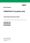
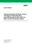
Customer Notification PG-FPL Flash Memory Programmer Operating Precautions Target Devices All 78K0/KX1+ devices All 78K0/FX1+ devices µPD78F0714 µPD78F0731 µPD78F0822B µPD78F0876 All V850ES/Kx1H devices All V850ES/Kx1+ devices All V850ES/Sx2 devices All V850ES/Fx2 devices All V850ES/Jx2 devices All V850ES/Hx2 devices µPD70F3187 Document No. TPS-LE-OP-TFPL-4 Date Published: July 2006 NEC Electronics (Europe) GmbH DISCLAIMER The related documents in this customer notification may include preliminary versions. However, preliminary versions may not have been marked as such. The information in this customer notification is current as of its date of publication. The information is subject to change without notice. For actual design-in, refer to the latest publications of NEC’s data sheets or data books, etc., for the most up-to-date specifications of NEC PRODUCT(S). Not all PRODUCT(S) and/or types are available in every country. Please check with an NEC sales representative for availability and additional information. No part of this customer notification may be copied or reproduced in any form or by any means without prior written consent of NEC. NEC assumes no responsibility for any errors that may appear in this customer notification. NEC does not assume any liability for infringement of patents, copyrights or other intellectual property rights of third parties by or arising from the use of NEC PRODUCT(S) listed in this customer notification or any other liability arising from the use of such PRODUCT(S). No license, express, implied or otherwise, is granted under any patents, copyrights or other intellectual property rights of NEC or others. Descriptions of circuits, software and other related information in this customer notification are provided for illustrative purposes of PRODUCT(S) operation and/or application examples only. The incorporation of these circuits, software and information in the design of customer’s equipment shall be done under the full responsibility of customer. NEC assumes no responsibility for any losses incurred by customers or third parties arising from the use of these circuits, software and information. While wherever feasible, NEC endeavors to enhance the quality, reliability and safe operation of PRODUCT(S) the customer agree and acknowledge that the possibility of defects and/or erroneous thereof cannot be eliminated entirely. To minimize risks of damage to property or injury (including death) to persons arising from defects and/or errors in PRODUCT(S) the customer must incorporate sufficient safety measures in their design, such as redundancy, fire-containment and anti-failure features. The customer agrees to indemnify NEC against and hold NEC harmless from any and all consequences of any and all claims, suits, actions or demands asserted against NEC made by a third party for damages caused by one or more of the items listed in the enclosed table of content of this customer notification for PRODUCT(S) supplied after the date of publication. Applicable Law: The law of the Federal Republic of Germany applies to all information provided by NEC to the Customer under this Operating Precaution document without the possibility of recourse to the Conflicts Law or the law of 5th July 1989 relating to the UN Convention on Contracts for the International Sale of Goods (the Vienna CISG agreement). Düsseldorf is the court of jurisdiction for all legal disputes arising directly or indirectly from this information. NEC is also entitled to make a claim against the Customer at his general court of jurisdiction. If the supplied goods/information are subject to German, European and/or North American export controls, the Customer shall comply with the relevant export control regulations in the event that the goods are exported and/or re-exported. If deliveries are exported without payment of duty at the request of the Customer, the Customer accepts liability for any subsequent customs administration claims with respect to NEC. Notes: (1) “NEC” as used in this statement means NEC Electronics Corporation and also includes its direct or indirect owned or controlled subsidiaries. (2) “PRODUCT(S)” means ‘NEC semiconductor products’ (NEC semiconductor products means any semiconductor product developed or manufactured by or for NEC) and/or ‘TOOLS’ (TOOLS means ‘hardware and/or software development tools’ for NEC semiconductor products’ developed, manufactured and supplied by ‘NEC’ and/or ‘hardware and/or software development tools’ supplied by NEC but developed and/or manufactured by independent 3rd Party vendors worldwide as their own product or on contract from NEC) 2 Customer Notification Table of Contents (A) Table of Operating Precautions ............................................................................................ 4 (B) Description of Operating Precautions.................................................................................. 5 (C) Cautions on Operating........................................................................................................... 9 (D) Valid Specification................................................................................................................ 11 (E) Revision History ................................................................................................................... 12 Customer Notification 3 Operating Precautions for PG-FPL (A) Table of Operating Precautions PG-FPL No. Outline Control Code A V1.00 A V1.10 A V1.20 A V1.22 A V1.30 A V1.40 A V1.50 1 Wrong behavior of the “Checksum after Program” function 2 Support of manual reset function 3 Transmission of program file may fail 4 Wrong address is displayed when a file is downloaded 5 Com-ports larger than 9 cannot be selected 6 Reset is output, when opening Device setup 7 Fixed wait-time(2s) after reset release for executing a write command 8 Security settings are executed illegally 9 Change of COM-port selection 10 Improvement of speed for write command 11 Support of devices with flash memory consisting of 255 or more blocks 12 Restriction related to Program and Verify commands in Block mode 13 Support of devices with code flash and data flash areas : Specification change not implemented : Not applicable or corrected : applicable 4 Customer Notification Operating Precautions for PG-FPL (B) Description of Operating Precautions No.1 Wrong behavior of the “Checksum after Program” function Details When Verify is executed individually after the “Checksum after Program” setting is made valid, Checksum is automatically performed after Verify is complete. No.2 Support of manual reset function Details A window that prompts a manual reset operation now appears even if a reset signal cannot be connected to the target cable. This window is opened by clicking the [Setup] button on the toolbar in the Main window, and the manual reset function becomes valid after checking the “Target Reset Message” checkbox in this window (Figure 1 or 2). Figure 1. Device Setup Window (Standard Tab) Figure 2. Device Setup Window (Advance Tab) Operation procedure when Target Reset Message is selected (1) Turn on the power to the target system. (2) Execute a write command. The following message appears and the operation is suspended. (3) Reset the target system. (4) Click the OK button to resume the write operation. Customer Notification 5 Operating Precautions for PG-FPL No.3 Transmission of program file may fail Details When using a program file that does not start from address 0h, data transmitted to the device becomes illegal in Program and Verify processing. No.4 Wrong address is displayed when a file is downloaded Details When a program file that does not start from address 0h is loaded, the display in the [load file] area in the programmer parameter window displays an address like “Area: 000000h-xxxxxxh”, which starts from address 0h. No.5 Com-ports larger than 9 cannot be selected Details If the USB driver “USB Serial Port” is recognized as COM10 or a later port, COM10 or a later port cannot be selected in the Device Setup window. No6 Reset is output, when opening Device setup Details When opening the Device Setup window, a RESET signal is output temporarily 6 Customer Notification Operating Precautions for PG-FPL No.7 Fixed wait-time(2s) after reset release for executing a write command Details When a write command is executed, the time taken from a reset signal release to a write command transmission was fixed to two seconds, regardless of the parameter file setting. This specification has been modified so that the value set in the parameter file is referenced. No.8 Security settings are executed illegally Details If the Program command or Autoprocedure (EPV) command is executed in an environment where GUI software V1.10 or earlier and parameter file V1.10 or later are used in a device that supports the security setting command, normally the security setting commands cannot be executed but they can be executed illegally. The items to be set illegally are “Disable Chip Erase” (disabling Chip Erase command), “Disable Block Erase” (disabling Block Erase command), and “Disable Program” (disabling Program command). No.9 Change of COM-port selection Details The specification has been changed so that all of the COM ports that are detected by the GUI software can be selected. This specification has been implemented in products with control code A (GUI: V1.22) or later. No.10 Improvement of speed for write command Details Unnecessary waits that occurred during communication with the device via the write command have been eliminated, and thus the communication speed has been improved. This modification has been implemented in products with control code A (GUI: V1.22) or later. Customer Notification 7 Operating Precautions for PG-FPL No.11 Support of devices with flash memory consisting of 255 or more blocks Details Devices with flash memory up to 512 blocks are supported This modification has been implemented in products with control code A (GUI: V1.30) or later. No.12 Restriction related to Program and Verify commands in Block mode Details If the Program or Verify command is executed in Block mode under the following conditions, data is transmitted from an address different from the start address set in Block mode. Condition 1: In the Operation Mode area of the Standard Device Setup dialog box, the Block radio button is selected and a value other than “0” is selected from the Start drop-down list. Condition 2: The used program file, which starts from an address lower than the one specified in condition 1, is selected by the [Load] command. [Workaround] There is no workaround. This restriction has been corrected in products with control code A (GUI: V1.40) or later. No.13 Support of devices with code flash and data flash areas Details Devices that have code flash and data flash, such as the V850ES/FX3, are supported now. Writing the code flash area is supported, but the data flash is not. A chip erase command will erase both, code flash and data flash. This modification has been implemented in products with control code A (GUI: V1.50) or later. 8 Customer Notification Operating Precautions for PG-FPL (C) Cautions on Operating No. 1 Power supply (a) The 5 V power supplied from the PG-FPL depends on the USB port of the host machine. Therefore, if the power supplied from the USB port is unstable or does not satisfy the specifications of the target device, supply the power from the target system. (b) If the MODE switch is set to MODE2, MODE3, or MODE4 (supplying power from the PG-FPL), the voltage set to the VDD/VDD2 pin is output when the PG-FPL is connected to the host machine. Therefore, be sure to disconnect the PG-FPL and the target system before connecting/disconnecting the device on the target system. No. 2 Caution when using PG-FPL in Windows 98/Me When the host machine is connected to the PG-FPL in the Windows 98 or Windows Me environment, the /RESET pin outputs a high level. If the target system is disconnected from the PG-FPL without executing a target command at all, the target system may be damaged. [Procedure 1] Execute the target command at least once after the PG-FPL is connected to the target system. Consequently, the /RESET pin output becomes low level. [Procedure 2] When another OS is used, the /RESET pin is low level from the first, so [Procedure 1] does not cause this problem. [Procedure 1] 1. The host machine and the PG-FPL are connected and the power is supplied via the USB port. 2. The target system is connected to the PG-FPL. 3. The target system is disconnected from the PG-FPL without executing the target command. [Procedure 2] 1. The host machine and the PG-FPL are connected and the power is supplied via the USB port. 2. The target system is connected to the PG-FPL. 3. The target system is disconnected from the PG-FPL after the target command is executed. No. 3 Caution for MODE switch Be sure to perform the MODE switch setting before using the PG-FPL. If the MODE switch is not set correctly, the PG-FPL or the target system may be damaged. For details on setting the MODE switch, refer to the PG-FPL user’s manual. No. 4 Checksum value differences between PG-FPL and PG-FP4 Since the checksum calculation method differs between the PG-FP4 and PG-FPL, the checksum value differs depending of the flash memory programmer to be used. Customer Notification 9 Operating Precautions for PG-FPL No. 5 General cautions on handling this product (a) Circumstances not covered by product guarantee • If the product was disassembled, altered, or repaired by the customer • If it was dropped, broken, or given another strong shock • Use at overvoltage, use outside guaranteed temperature range, storing outside guaranteed temperature range • If power was turned on while the USB cable or target system connection was in an unsatisfactory state • If the USB cable, connection cable, or the like was bent or pulled excessively • If a power supply other than the one supplied with the product is used • If the product got wet • If the product and target system were connected while a potential difference existed between the GND of the product and the GND of the target system • If a connector or cable was removed while the power was being supplied to the product • If an excessive load was placed on a connector or socket (b) Safety precaution • Be careful of electrical shock. There is a danger of electrical shock if the product is used as described above in (a) Circumstances not covered by product guarantee. 10 Customer Notification Operating Precautions for PG-FPL (D) Valid Specification Item Date published Document No. Document Title 1 September 2005 U17788E PG-FPL User’s Manual Customer Notification 11 Operating Precautions for PG-FPL (E) Revision History Item Date published Document No. Comment 1 October 2005 TPS-LE-OP-TFPL-1 1st Release 2 January 2006 TPS-LE-OP-TFPL-2 1st Update 3 April 2006 TPS-LE-OP-TFPL-3 2nd Update 4 July 2006 TPS-LE-OP-TFPL-3 3rd Update 12 Customer Notification