1
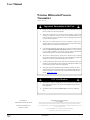
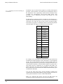
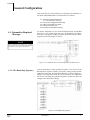
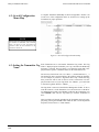
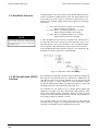
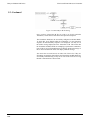
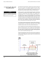
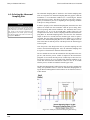
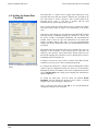
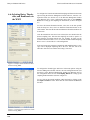
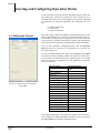
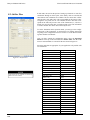
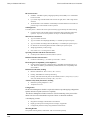
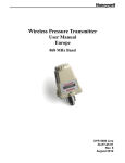
Honeywell Industrial Wireless
5.2: Baud Rate Selection
Wireless Differential Pressure Transmitter
The RF Baud Rate refers to the speed at which the Base Radio and Transmitters communicate. The RF baud rate for the Base Radio and the Transmitter must be the same in order for successful communication to occur.
There are three selectable settings with the fastest update times and ranges
listed below:
•
•
•
NOTE
If you change the baud rate of a Transmitter, you
must also change the baud rate of the Base Radio
and all other Transmitters that are communicating
with that Base Radio.
4.8K– Rate of 4.8 Kbaud (Update every 20 seconds)
- Range of 3000ft (Line of Sight)
19.2K– Rate of 19.2 Kbaud (Update every 5 seconds)
- Range of 2000ft to 2500ft (Line of Sight)
76.8K– Rate of 76.8 Kbaud (Update every 1 second)
- Range of 500ft to 750ft (Line of Sight)
A faster RF Baud Rate allows the user to transmit more information in a
given period of time, but it will also limit the Transmitter’s range. If you
need more distance out of your Transmitters or are encountering difficulties by frequently losing communications, then select a slower baud rate.
Follow the Base Radio menu map shown in Figure 5.2 to configure the RF
Baud Rate. The factory default is the 19.2K Baud Rate.
Figure 5.2: Menu Map to Baud Rate Setting
5.3: RF Identification (RF ID)
Selection
Each Transmitter is identified by the Base Radio and WMT according to the
RF ID given to that particular unit. Two Transmitters CANNOT have the
same RF ID and be on the same RF Channel (if you do not know the RF
Channel see section 5.1). If the Transmitter is in the Operations Sequence,
pressing the ENTER button displays the Read-Only Sequence on the LCD.
The RF ID of that unit will be displayed in this format: ID 3.
All Transmitters in your system are set to a default RF ID number upon
shipment. For example, if you have ordered a Base Radio and three Transmitters, the Transmitters will be configured to RF ID’s 0, 0 and 0. You must
set these units to three different IDs between 1 and 100. The Transmitters in
this example could be set to RF IDs 1, 2 and 3.
First determine the RF ID’s you’d like to give each unit. Then follow the
menu map shown in Figure 5.3 to configure the RF ID. The factory default
is RF ID 0, which disables the RF communication of the unit.
19 Rev. 5
08/06
User Manual