1
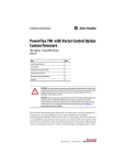
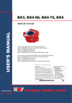
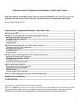
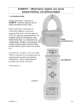
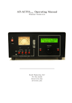
SALUKI ENGINEERING COMPANY SOUTHERN ILLINOIS POWER COOPERATIVE LAKE TEMPERATURE MONITORING SYSTEM USER MANUAL Prepared by Saluki Engineering Team #62 Client: Scott Achelpohl of Southern Illinois Power Cooperative SEC Reference # : S11-62-SIPCLAKE User Manual - 1 Contents User Guide - Buoy .............................................................................................................. 3 User Guide – CPU .............................................................................................................. 8 User Guide – Power System ............................................................................................... 9 User Guide – Temperature Sensors .................................................................................. 13 User Guide – GPS............................................................................................................. 14 User Guide – Transceiver ................................................................................................. 17 Bibliography ..................................................................................................................... 26 User Manual - 2 User Guide - Buoy Assembly of Watertight Canister 1. Insert board fully into canister until it “locks” into place Figure 1 – insertion of board into canister Figure 2 – Board locked fully into place. White handle is fully inserted into the cap. 2. Tighten down cap fully until “groves lineup” a. Note – petroleum jelly should be used on the threads every 10 times to allow easy on and off of the cap 3. Insert canister into aluminum housing with groves lined up with the hinge assembly screw heads. User Manual - 3 Figure 3 – Hinge assembly screw heads Figure 4 – Grooves lined up with screw heads 4. Spin the canister 180 degrees to lock into place Figure 5 – Canister locked into place. Note relation of groove to screw heads User Manual - 4 5. Insert 2 lag bolts to ensure canister remains in housing. Figure 7 – Lag bolts in place Insertion of Temperature Probe Protector 1. The temperature probe protector is simply slid down into the buoy’s down pipe. a. Mount sits freely on top of the recessed pipe Figure 1 – Display of recessed down pipe. Note the mount lays directly on top of the orange down pipe. User Manual - 5 Buoy Assembly Figure 1 – Preassembled MB-300 Buoy 1. Mount the supplied Aluminum Canister Housing to hinge using the supplied ½” hardware until lock washer is flush with nut. a. Hardware – bolt, lock washer, and nut Figure 2 – Hinge Assembly User Manual - 6 2. Tighten tie down bolts to buoy Figure 3 – Tie down bolts 3. Attach light to top of the aluminum housing using supplied ½” bolts Figure 4 – Attachment of light to aluminum housing User Manual - 7 User Guide – CPU Information will be provided to the client at a later date. The CPU shouldn’t need any consumer interaction. User Manual - 8 User Guide – Power System Power Supply Subsystem User Guide dc-dc converter board connections Input connections The dc-dc converter board connects to the solar charging circuits via a two conductor cable. The dc-dc converter input wires are labeled in the figure below. Each connection is established between devices via the terminal block, with labels, located on the shelf within the watertight enclosure. ̴12 V- 17 V (filtered; unregulated); maximum current: 1.5 A Ground Figure 1: input connections The wire labeled in the figure as [12 V- 17 V (filtered; unregulated); maximum current: 1.5 A] connects to the red wire of the two-conductor cable which is attached to the solar charging circuit. The black wire of the two-conductor cable connects to the wire labeled User Manual - 9 [Ground] in the figure above. These are the two input connections of the dc-dc converter board. Output Connections The dc-dc converter board connects provides power to the CPU, GPS, temperature probes, and transmitter. The dc-dc converter output wires are labeled in the figure below. As with the input connections; each connection between devices is established via the terminal block, with labels, located on the shelf within the watertight enclosure. 3.3 V (filtered; regulated); maximum current: 300 mA Ground 5 V (filtered; regulated); maximum current: 500 mA ̴12 V- 17 V (filtered; unregulated); maximum current: 500 mA 2.5 V (filtered; regulated); maximum current: 8 mA A Figure 2: output connections The CPU connects to the 3.3 V voltage source as well as the 5 V voltage source these outputs are labeled in the figure 2 above as [3.3 V (filtered; regulated); maximum current: 300 mA] and [5 V (filtered; regulated); maximum current: 500 mA]. The appropriate connection points are labeled on the shelf at the terminal block location. The GPS unit connects to the 5 V voltage source of the dc-dc converter and shares its connection with the CPU at the terminal block. The appropriate connection points are labeled on the shelf at the terminal block location. User Manual - 10 The temperature probes connect to the 2.5 V voltage source which has the label [2.5 V (filtered; regulated); maximum current: 8 mA] in figure 2. The appropriate connection points are labeled on the shelf at the terminal block location. The transmitter connects to the 12 – 17 V voltage source which has the label [12 V- 17 V (filtered; unregulated); maximum current: 500 mA] in figure 2. The appropriate connection points are labeled on the shelf at the terminal block location. IMPORTANT NOTE: Each connection between the dc-dc converter and a system device, given above, assumes a connection to the ground reference which is labeled in figure 2 above as [Ground.] Troubleshooting: The output voltages may be measured using a dc voltmeter at the terminal block with [Ground] as the reference. Each voltage should be within 300 mV of its rated value. These values are given above in figure 2 and also provided within the labels at terminal block. Case 1: None of the devices have power. a) Ensure all connections between the dc-dc converter and system devices (i.e. CPU, GPS, temperature probes, and transmitter) are well connected and connected correctly. Ensure all connections between dc-dc converter and solar charging circuits are well connected and connected correctly. b) If problem persist measure dc-dc converter input voltage, with respect to ground, at the terminal block, ensuring the measured voltage is between 12 and 17 V. c) If the required voltage range of 12-17 V is present at the terminal block measure the input voltage (see figure 1) with respect to ground on the dc-dc converter board ensuring a voltage exists between 12 V and 17 V. If the required voltage range is not present, electrically disconnect all solar panel, charge controller, and battery units from the wire harness and measure each solar charging circuit output ensuring voltages in the range of 12 V and 17 V. If any or all do not output the 12-17 V then place solar panels in direct sunlight for 4-12 hours to recharge internal battery of solar charging circuit and measure output voltage(s) ensuring a voltage in the range of 12-17 V is present. If not, replace solar charging circuit(s) (Fondriest: SP5). End troubleshooting procedure. d) If the required voltage is present on the dc-dc converter board measure the input voltage of each voltage regulator (see drawing Kbuoy-1 and corresponding datasheet for pin number(s)) . e) If all input voltages are present and correct, measure output voltages of each voltage regulator ensuring the given voltage regulator is supplying the appropriate level dc voltage. User Manual - 11 f) If the voltage is present at the output pins of the voltage regulators replace the dcdc converter output wires between the dc-dc converter board and the terminal block. End troubleshooting procedure. Case 2: Some of the devices of the system do not have power. a) Determine which devices do not have power and measure the corresponding voltages at the terminal block for the devices not powered. b) If the voltages at the terminal block are present measure the voltage(s) on the dcdc converter board ensuring they are at the appropriate voltage levels. If the voltage(s) are not present replace the wire connecting the dc-dc converter board to the terminal block. End troubleshooting procedure. c) If the voltages at the dc-dc converter board outputs are present, measure the input voltage of the corresponding voltage regulator located on the dc-dc converter board (utilize Kbouy-1 and datasheet(s) for the corresponding voltage(s)) d) If the input voltage is present measure the output voltage of the same voltage regulator and ensure it is at its rated value. If not, replace the given voltage regulator. End troubleshooting procedure. e) If the input voltage is not present replace the dc-dc converter board. Power plant power supply Plug the power supply into a 115 Vac 60 Hz outlet. Electrically connect the power supply outputs to the power inputs of the CPU enclosure. All of these output and input connections have identical labeling on both enclosures to reduce the risk of inappropriate connections. Ensure all connections between power supply and connected devices are well connected and correctly connected. Case 1: The power plant power supply does not power connected devices. a) Ensure the power supply is plugged into the 120 Vac 60 Hz outlet. b) If the power supply is plugged in measure the output voltages. If all outputs are approximately 0 V unplug the power supply and check the panel mount fuse of the power supply. c) If the fuse is blown then replace fuse. End troubleshooting procedure. d) If the fuse is not blown replace the dc power supply circuit board located within the power plant dc power supply enclosure. End troubleshooting procedure. User Manual - 12 User Guide – Temperature Sensors Temperature probe section for Users Manual In order for the temperature probes to function they need to be connected properly. There are four wire connections that need to be made for each sensor. The purple wire is the reference ground and should be connected to ground. The clear wire is the shield and should also be connected to ground. The black wire is for the excitation voltage and should be connected to the pin on the cpu unit providing the 2,500mV D.C. output. Multiple probes can be connected to the same excitation channel. The red wire provides the output voltage and needs to be connected to the pin on the cpu unit that will measure the voltage difference between the red wire and ground. After the proper connections have been securely made and after the cpu unit and all of the electrical components are placed in their water tight enclosure, the temperature probes can be submerged into the water. The sensors will be lowered down through the bottom of the buoy and the user should either use a weighting system or secure the probes to the aluminum tube at their proper locations as the probes are not weighted. The sensors are designed to provide an output voltage from 0V to 2.3V depending on the temperature for the range of -50°C to +70°C. For the temperature range of 0°F to 100°F the output voltage will be between 1.080V and 2.030V which corresponds directly to the temperature. Maintanance The CS 109-L temperature probes require minimal maintenance. It is recommended to check the probes every six months for signs of bacterial growth. If there is any growth on the probe tips it can be easily wiped off with a cloth. It is also recommended to periodically check the cabling for signs of damage or moisture intrusion. Troubleshooting The sensors should provide accurate readings if they are installed properly. If the sensors are giving incorrect temperature readings, verify that the correct connections were made. The black wire should be connected to the excitation channel, the purple wire connected to ground, and the red wire to the output channel. Also, check for damage or moisture intrusion. If the sensors are giving an unstable temperature reading, check that the clear shield wire is properly grounded. User Manual - 13 User Guide – GPS The GPS subsystem must first be tested with a PC via the USB port. Install the battery on the underside of the module with the + side facing away from the module. Connect the Antenna to the MMCX connector as shown in Figure 1. Place the Antenna where it can get satellite reception such as near a window. Connect the module to your PC with the USB A to Mini B cable also show in Figure 1. Install the USB drivers (internet connection required). Install the Linx MDEV-GPS software (provided). Set the jumper blocks to the Shorted position as shown in Figure 2. Figure 2: Jumpers Shorted-USB to PC Mode Figure 1: Module Connections User Manual - 14 Launch the Linx MDEV-GPS software as shown below. Select the appropriate COM Port and click CLOSE. Click on the GPS PAUSED button to display the GPS reading. This will cause the button to change to say READING GPS. Select ALL NMEA-0183 records received under the GPS Data Viewing Mode drop-down menu as shown below. User Manual - 15 Once the GPS has a lock (see LEDs) it will display the appropriate data as shown below. Disconnect the USB cable from the module. User Manual - 16 Microcontroller Mode Set the jumpers to the open position as shown in Figure 3. Figure 3: Microcontroller Mode User Guide – Transceiver Health and Safety Issues There is a risk of radiation exposure if the proper restrictions are not followed. This device complies with FCC radiation exposure limits as set forth for an uncontrolled environment. The system that is being used will have the ability to operate using three different types of antennas. The following antennas should be kept at least 20 cm (0.67 ft) from your body to prevent unsafe levels or radiation exposure. ¼ wave rubber whip antenna (Testing Antenna) ¼ wave mobile antenna (Buoy Antenna) The following antennas should be kept at least 2 m (6.6 ft) from your body to prevent unsafe levels or radiation exposure. These antennas should not be installed indoors. 6dB 3 element Yagi (Power Plant Antenna) Source: Coyote Datacom Inc. Proper precautions need to be taken when servicing the transceiver. The device should be powered down when being serviced. Water and electricity do not mix service the unit indoors in order to prevent damage as well as electrocution. When servicing the buoy disconnect the power so that the transceiver is not omitting any unwanted radiation. User Manual - 17 Warning… Any Modification to the CDR-915XL transceiver could violate the FCC CDR 15.247 certification causing the unit to affect the surrounding radio frequency spectrum. Do not tamper with the CDR915XL transceiver for any reason. All service should be done by a qualified radio technician that carries all of the proper certificates and training. Contents of Subsystem Device Description CDR-915XL Transceiver Modules INT-232/485 Interface Boards CBL-RS232 Serial Cable Ant-MUF9000 Mobile Antenna ANT-MXRMY A9 303 6d Bd Yagi Antenna Mounting hardware protoboard Qty 2 2 2 1 1 2 User Manual - 18 Device Characteristics CDR-915XL Transceiver Frequency: Range: RF Data Rate: Transmitter Ouput: Input Voltage: Input Current: U.S. (FCC) Operating Software 902-928 MHz Up to 10 miles 100 kbps 200 mWatt 8-15 VDC 250 mA Transmit Mode & 70 mA Receive Mode CFR.15.247 Approved Windows Application CDR-915XL Pin Definitions 1. G 2. CTS 3. DTR 4. RXD 5. TXD 6. RST 7. FRM 8. A2 9. A1 10. VCC Pin 1 – Ground - This is the power and signal ground for the data radio. Pin 2 - Clear To Send - CTS is a TTL output from the radio which indicates the device's readiness. The radio will drive the signal low to indicate that it can accept serial data. You must stop sending serial data when this signal is driven high or you risk overrunning the buffers and losing data. Pin 3 - Data Terminal Ready -DTR is a TTL input to the radio which is used to control the device's mode. DTR should be held low during normal operation and only driven high to enter command mode. Pin 4 - Receive Data - RXD is the TTL-level, asynchronous, serial data output from the radio to the user device. Incoming data (and responses to commands) will be driven on this line. Serial data is formatted in the standard way, with a single low start bit, eight data bits (LSB to MSB), parity (if enabled), and then a high stop bit(s). The baud rate, parity, and stop bit settings are user-configurable. Pin 5 - Transmit Data - TXD is the TTL-level, asynchronous, serial data input to the radio from the user device. Outgoing data (and commands) should be driven into this line. TXD expects the serial data to be formatted the same was as for RXD (above). Pin 6 – Reset - Driving RST low will hold the radio in reset. This pin should be left open during normal operation. Pin 7 – Frame - Frame is held high while data is being returned on RXD. Pins 8 & 9 – Reserved - These signals are not user-supported and should be left unconnected. Pin 10 – Power - VCC is the power to the radio. It should be kept between 9V and 28V DC. User Manual - 19 INT-232/485 Combo Interface Board Power Connector: Current: Power Jack (2.5mm x 5.5mm) Yellow LED Green LED Red LED 9-28 VDC 1000mA Jack center is positive Radio is ready to accept data from user connected equipment Data is being sent from the radio to the user-connected equipment Data is being sent from the user connected equipment to radio PIN 1 – RS-485 A PIN 2 – RD (Receive Data) is serial data from the radio to the user device. PIN 3 – TD (Transmit Data) is serial data from the user device to the radio. PIN 4 – DTR (Data Terminal Ready) indicates the user device is ready to send data to the radio for transmission. When this line is high, the radio will transmit any data across the RF network. When this line is low, the radio will process the data as commands. If left unconnected, this line will be high. PIN 5 – GND (Ground) is the interface common. PIN 6 – DSR (Data Set Ready) is always held high by the radio. PIN 7 – RTS (Request To Send) is not connected on an RS-232 Interface board. PIN 8 – CTS (Clear To Send) is used to indicate to the user device that the radio can accept more data. When this line is high, the user device is clear to send more data. When this line is low, the user device should not send data. (This line may be ignored at baud rates of 2400 and 4800 bps. The TX Packet size should be changed to 150 bytes to prevent a buffer overflow.) PIN 9 – RS-485 B User Manual - 20 Coaxial Cable Selection Coaxial Cable (Loss of 12.5 dB per 100’) CBL-RSMA-NM-RG-58 – 1 foot length CBL-RSMA-NM-RG-58 – 3 foot length CBL-RSMA-NM-RG-58 – 12 foot length CBL-RSMA-NM-RG-58 – 20 foot length Supplier Price Per Unit Coyote Datacom Coyote Datacom Coyote Datacom Coyote Datacom $22.00 $23.00 $25.00 $30.00 Coaxial Cable (Loss of 3.2 dB per 100’) CBL-NM-NM-LMR-400 – 25 foot length CBL-NM-NM-LMR-400 - 50 foot length CBL-NM-NM-LMR-400 - 100 foot length Supplier Price Per Unit Coyote Datacom Coyote Datacom Coyote Datacom $57.00 $94.00 $190.00 Custom cable lengths can be purchased from other suppliers. In order to determine the amount of power loss use the following equations for ordering cable lengths. RG-58 Coaxial Cable 12.5 dB loss every 100’ of cable (Example: 300’ of cable will result in 37.5 dB power loss) LMR-400 Coaxial Cable 3.2 dB loss every 100’ of cable (Example: 300’ of cable will result in 9.6 dB power loss) The RF connectors that are used with the CDR-915XL is (Reverse SMA). The RF connector that is used on the 6dB 3 element Yagi antenna is (N-Female). The proper tools are required by the technician to install these RF connectors. Antenna Selection Buoy Antenna: The antenna that is mounted on the buoy is a mobile antenna it only requires to be connected to the reverse SMA connector of the CDR-915XL that is within the watertight capsule. The coaxial cable should be run thru a water tight gland nut to prevent moisture from entering the capsule. If the mobile antenna must be replaced run the replacement cable the same route that the present mobile antenna cable is ran. The mobile antenna shouldn’t need any service since it shouldn’t experience any for seen wear and tear. Power Plant Antenna: The antenna that will be mounted on the SIPC power plant must be mounted to a sturdy structure as the radio tower. The 6dB Yagi antenna is a directional antenna and needs to be mounted in the direction of the expected radio transmission. The antenna should have a open view of the horizon without any obstructions in front of it. For the best reception keep other antennas away from the Yagi antenna. User Manual - 21 Since the Yagi is being mounted at a larger than normal distance the cable length must follow the characteristics in the Coaxial Cable Guidelines tables. When installing or servicing the Yagi antenna makesure that the transceiver is powered off so that unsafe levels of radiation doesn’t come in contact with the human body. The connector of the cable that will be connecting to the Yagi antenna is a N-Type-Female connector. The other end of that coax cable has to be a reverse SMA connector where it will connect to the CDR-915XL transceiver. Configuring CDR-915XL using INT-232/485 Combo Interface Board The CDR-915XL comes preset with default setting. During configuration the user is always able to return the CDR-915XL back to default settings is something causes the transceiver to not operate. Steps to configure your CDR-915XL 1. Install Radio Setup Software from the provided software. 2. Once the installation of this software is complete, locate a serial communication port on the back of your computer. If there isn’t a port available a USB to Serial cable adapter can be purchased from any major computer store. 3. Plug the INT-232/485 Combo Interface Board into your computer using the supplied serial communication cable. 4. Once the CDR-915XL and INT-232/485 Combo Interface Board are plugged into the computer you can run the Radio Setup Software that you installed in previous steps. 5. The opening screen should look like the following: User Manual - 22 (If the connection status is disconnected, change the port number until the connection status states that it is READY) 6. To gain information about you CDR-915XL you can click on the information icon on the left hand side of the screen. User Manual - 23 7. To configure your CDR-915XL transceiver to a different radio frequency consult the information screening and locate the requested radio frequency out of the list of frequencies. Make a note of the channel number listed in front of the frequency. 8. Next you will click on the Configuration icon on the left hand side of the screen which will look like the following: Set the group value to the channel value you made a note of from the information page. If you have multiple transceivers you will have to assign each transceiver a different address. The group number will remain the same. 9. Make the changes that are illustrated above. 10. Once changes are made click on the configuration icon again. A window will pop up asking if you would like to save the configuration, select yes. 11. The CDR-915XL will now have the updated radio frequency. Radio Frequency Site Survey If steps 1-4 have been completed you can reopen the Radio Setup Software. If everything is hooked up correctly the screen should look like step 5. If the screen says disconnected follow the instructions included with step 5. 6. Click on the Site Survey icon on the left hand side of the screen, the screen should look similar to the following: User Manual - 24 (The spectrum analyzer should look different at every location, don’t compare your screen to the image above.) 7. Click the reset button on the top right hand corner of the window. 8. If there are any radio frequencies in the spectrum of 902-928 MHz they should show up on the spectrum graph. (Make sure that the CDR-915XL has an antenna hooked to its SMA reverse connector when doing a Site Survey.) 9. Using the Site Survey feature allows for checking to see if the radio frequency you would like to configure your transceiver device to is available. 10. Once you have completed your site survey in one location, try a location nearby too see if the results are the same as before. Radio frequencies can be altered by physical structures as well as foliage and water. 11. Upon completion shut down the Radio Setup Software and disconnect the serial communication cable from the computer and the INT-232/485 Combo Interface Board. 12. Store equipment in a dry secure location where damage cannot accidently occur to the CDR-915XL device or the INT-232/485 Combo Interface Board. User Manual - 25 Bibliography Campbell Scientific. Brochure for 109 Temperature Probe for CR200(X)-Series Dataloggers. Campbell Scientific When Measurements Matter. [Online] January 2011. [Cited: 5 8, 2011.] http://www.campbellsci.com/documents/product-brochures/b_109.pdf. Coyote DataCom, Inc. CDR-915XL Advanced SS Data Transceiver. [Online] November 11, 2007. [Cited: Nov 2, 2011.] Fondriest Technologies. MB-300/400 User Manual. Beavercreek, OH: Fondriest Technologies, 2010. NexSens Technology, Inc. Web. <nexsens.com/pdf/nexsens_mb300_400_manual.pdf>. Lenk, Ron. Practical Design of Power Supplies. New York, NY [u.a.: McGraw-Hill [u.a., 1998. Print. McMaster-Carr. Web. 25 Nov. 2011. <http://www.mcmaster.com/>. National Oilwell Varco. Web. 1 Nov. 2011. <http://www.nov.com>. Mr. Ortega from the NOV Sales Department helped to donate the fiberglass pipe to the team – phone number (713) 375 - 3700. "NexSens MB-300 Inland Lakes Data Buoy | NexSens." NexSens Technology, Inc. Web. 15 Sept. 2010. <http://nexsens.com/products/nexsens_mb-300.htm>. Parallax Inc. Web. 25 Nov. 2011. < http://www.parallax.com>. Scherz, Paul. "Chapter 10 Voltage Regulators and Power Supplies." Practical Electronics for Inventors. New York: McGraw-Hill, 2007. Print. User Manual - 26