1
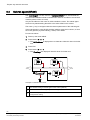
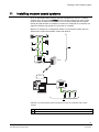
Before configuring the system 14 Before configuring the system Before commissioning the SiPass Entro system, the installer should read and complete the checklist [ 75] . 14.1 Check the communication circuits Go to all units in the system and check that they are communicating. When all units are connected (but with all removable terminal blocks disconnected in drop boxes and door controllers), check on reader block nos. 3 and 4 in drop boxes, door controllers and segment controllers that the resistance on the global and the local communication circuit respectively, is 60 Ω (ohm) plus the cable resistance. If the resistance is 120 Ω plus the cable resistance, one termination resistor is missing. If the resistance is much less than 60 Ω, there is a short circuit in the communications circuit. If the resistance is much greater than 120 Ω (open circuit), there is a break in the circuit or the termination is missing in both ends. If using a LAN, check that all cables are correctly connected to the LAN. 14.2 Check the power supply Connect the power supplies. Check that the voltage is approximately that of the power supply output and that + and – are in the right positions. Remember that a voltage drop (between the highest and lowest potential) larger than 5V between units may influence the quality of the RS485 communication. 74 Building Technologies Fire Safety & Security Products 020_SiPass_Entro_6_5_A24205-A335-B317_e_en 10.03.2010