1
Cat. No. W08E-EN-01
Cat. No. W08E-EN-01
Software Release 2.0
CX-Supervisor Software Release 2.0
CX-Supervisor
GETTING STARTED
GETTING STARTED
Authorized Distributor:
Cat. No. W08E-EN-01
Note: Specifications subject to change without notice.
Printed in Europe
CX-Supervisor
Getting Started
Software Release 2.0
OMRON
Getting Started with CX-Supervisor
Notice
OMRON products are manufactured for use according to proper procedures by a qualified operator
and only for the purposes described in this manual.
The following conventions are used to indicate and classify precautions in this manual. Always heed
the information provided in them. Failure to heed precautions can result in injury to people or
damage to the product.
DANGER!
Indicates information that, if not heeded, is likely to result in loss of life or
serious injury.
WARNING
Indicates information that, if not heeded, could possibly result in loss of
life or serious injury.
Caution
Indicates information that, if not heeded, could result in relatively serious
or minor injury, damage to the product, or faulty operation.
OMRON Product References
All OMRON products are capitalised in this manual. The word “Unit” is also capitalised when it
refers to an OMRON product, regardless of whether or not it appears in the proper name of the
product.
The abbreviation “PLC” means Programmable Logic Controller and is not used as an abbreviation for
anything else.
Revision 2.0
Page i
Getting Started with CX-Supervisor
Page ii
OMRON
Revision 2.0
OMRON
Getting Started with CX-Supervisor
Visual Aids
The following headings appear in the left column of the manual to help you locate different types of
information.
Note:
1, 2, 3…
Indicates information of particular interest for efficient and convenient
operation of the product.
Indicates lists of one sort or another, such as procedures, checklists etc.
Represents a shortcut on the Toolbar to one of the options available on the
menu of the same window.
Indicates a program must be started, usually by clicking the appropriate
option under the standard Windows ‘Start’ button.
OMRON, 2007
All rights reserved. No part of this publication may be reproduced, stored in a retrieval system, or
transmitted, in any form, or by any means, mechanical, electronic, photocopying, recording, or
otherwise, without the prior written permission of OMRON.
All copyright and trademarks acknowledged.
No patent liability is assumed with respect to the use of the information contained herein. Moreover,
because OMRON is constantly striving to improve its high-quality products, the information
contained in this manual is subject to change without notice. Every precaution has been taken in the
preparation of this manual. Nevertheless, OMRON assumes no responsibility for errors or omissions.
Neither is any liability assumed for damages resulting from the use of the information contained in
this publication.
Revision 2.0
Page iii
Getting Started with CX-Supervisor
Page iv
OMRON
Revision 2.0
OMRON
Getting Started with CX-Supervisor
About this Manual
This manual describes the CX-Supervisor application and its installation.
This manual contains the following:
Getting Started. A description of CX-Supervisor installation and its use for the first time.
Basic Tutorial. A quick guide of use for the first time.
Advanced Tutorial. A detailed step by step tutorial for the key areas.
A Glossary of Terms and Index are also provided.
Warning:
Revision 2.0
Failure to read and understand the information provided in this manual may result in
personal injury or death, damage to the product, or product failure. Please read each
section in its entirety and be sure you understand the information provided in the
section and related sections before attempting any of the procedures or operations
given.
Page v
Getting Started with CX-Supervisor
Page vi
OMRON
Revision 2.0
OMRON
Getting Started with CX-Supervisor
TABLE OF CONTENTS
CX-Supervisor ............................................................................................................... Page
Getting Started with CX-Supervisor ............................................ 1
Welcome to CX-Supervisor........................................................................................... 1
About this Manual ......................................................................................................... 2
System Requirements .................................................................................................... 3
Installing CX-Supervisor ............................................................................................... 4
Copy Protection ............................................................................................................. 4
Starting CX-Supervisor.................................................................................................. 8
Customising CX-Supervisor Settings ............................................................................ 9
The CX-Supervisor Help System................................................................................... 9
Basic Tutorial................................................................................ 11
Advanced Tutorial........................................................................ 25
Glossary of Terms......................................................................... 49
Index............................................................................................... 53
Revision 2.0
Page vii
OMRON
Getting Started with CX-Supervisor
Getting Started with CX-Supervisor
This chapter introduces the CX-Supervisor application to a new user.
Welcome to CX-Supervisor
CX-Supervisor is dedicated to the design and operation of PC based visualisation and machine
control. It is not only simple to use for small supervisory and control tasks, but it also offers a wealth
of power for the design of the most sophisticated applications. CX-Supervisor boasts powerful
functions for a wide range of PC based HMI requirements. Simple applications can be created rapidly
with the aid of a large number of predefined functions and libraries, and even very complex
applications can be generated with a powerful programming language or VBScript. CX-Supervisor
has an extremely simple, intuitive handling and high user friendliness. Importing ActiveX®
components makes it possible to create flexible applications and extend functionality.
CX-Supervisor offers a comprehensive range of facilities for the developer and is capable of
developing solutions with the following features:
♦
Operator interface to processes
♦
Data acquisition and monitoring
♦
Information management
♦
Manufacturing control
♦
Supervisory control
♦
Batch sequencing
♦
Continuous process control
♦
Alarm monitoring and reporting
♦
Material handling (monitoring and control)
♦
Simulation and modelling through graphic animation
♦
Data Logging
♦
Error logging
♦
Project Editor and cross referencing
♦
Multi-lingual user interfaces
♦
Report editor
♦
Database Connectivity
♦
Connection to OPC Servers
♦
Use of ActiveX objects
Revision 2.0
Page 1
Getting Started with CX-Supervisor
♦
OMRON
Use of Visual Basic script and Java Script
CX-Supervisor runs on standard PC desktop computers running Microsoft Windows. CX-Supervisor
is intuitive and easy to use, and allows the developer to rapidly configure, test and debug a project.
CX-Supervisor comprises two separate executable Windows programs, CX-Supervisor Development
environment and CX-Supervisor Runtime environment. Applications are created and tested using the
development environment and then delivered as a final customer application with the runtime
environment.
The runtime-only environment may only be used for executing an application previously generated
using the development environment. It is not possible to generate a new runtime application using
the runtime environment.
Note:
It is important that this copy of the CX-Supervisor software is registered on the OMRON
web site, in order to qualify for technical support and maintenance updates. OMRON will
not be able to help unless this copy has been registered.
About this Manual
This manual helps a new user get started with CX-Supervisor, by describing the software installation
and computer configuration, and by leading the user through the basics of CX-Supervisor application
programming.
Separate OMRON manuals describe the related software products; CX-Server, CX-Programmer etc.
Some small example applications are included with the CX-Supervisor software to demonstrate some
of the most useful features. These can be used to help with product familiarity.
CX-Supervisor comes with a comprehensive context-sensitive on-line help system, which is designed
to complement this manual, and provide a quick reference at any point in the CX-Supervisor
application when the manual is not to hand. This general help system uses a fast 'hypertext' system
that allows progressively more information to be obtained about any topic by selecting keywords
within the descriptive text.
Throughout this manual, it is assumed that the user has a working knowledge of Microsoft Windows,
and can:
♦
♦
♦
♦
♦
♦
♦
Page 2
Use the keyboard and mouse.
Select options from Windows menus.
Operate dialog boxes.
Locate, open and save data files.
Edit, cut and paste text.
Drag and drop.
Start programs from the “START” button.
Revision 2.0
OMRON
Getting Started with CX-Supervisor
If Windows has not been used before, spending some time working with the Microsoft
documentation is recommended before using CX-Supervisor.
This introductory chapter deals with several important aspects of installing CX-Supervisor and setting
it up for use. It is recommended that this entire chapter be read before installing the software.
System Requirements
CX-Supervisor operates on the following hardware and operating systems:
Hardware Requirements
The following configuration is the minimum system requirements for running CX-Supervisor:
♦
IBM PC compatible 600 MHz Pentium II processor or better.
♦
256Mbyte of RAM minimum.
♦
650Mbyte available hard disk space.
♦
1024 x 768 XGA display.
♦
A CD ROM drive is required in order to install the CX-Supervisor software.
Note:
These are requirements when using minimum operating system. For other operating
systems consult your documentation.
The following configuration is the recommended minimum system environment for running CXSupervisor effectively:
♦
IBM PC compatible Pentium II 1.0 GHz processor.
♦
512Mbyte of RAM.
♦
650Mbyte available hard disk space.
♦
1024 x 768 XGA display.
Operating Systems and Environments
The operating systems on which this software should be run are:
♦
Microsoft Windows 2000 (SP2)
♦
Microsoft Windows XP Professional
Note:
This product does not install or run on Windows NT, Windows ME, Windows98 or
Windows 95.
Note:
CX-Supervisor is not guaranteed to be compatible with computers running Windows
emulation (e.g. Apple Macintosh or VMWare).
Revision 2.0
Page 3
Getting Started with CX-Supervisor
Note:
OMRON
Internet Explorer 5.0 or later is required to use the version of CX-Server installed with this
product
Interfaces to Hardware Communications
CX-Supervisor utilises communications driver CX-Server for direct communication with OMRON
factory automation equipment.
If it is intended for a PLC to be connected to the development computer for executing program code
and testing, one of the following is required:
♦
RS-232C connection via a standard serial port on the computer (COM1 etc.)
♦
RS-422 connection to a 422 serial board
♦
Standard Ethernet board
♦
Standard USB port
♦ An OMRON Network Service Board
Refer to the appropriate hardware system manuals for full information about connecting and
configuring these devices for the environment.
Installing CX-Supervisor
The CX-Supervisor software is supplied on CD-ROM and is installed easily from within Windows.
To install CX-Supervisor, load the disk in the CD-ROM drive. The AutoRun feature should
automatically start the setup program and the installation of CX-Supervisor should take no more than
a few minutes. If this has been disabled see the README.TXT on the CD-ROM for manual
launching instructions.
After installation the text file README.HTML in the CX-Supervisor directory contains up-to-date
information about the software. Read this file for details of any changes or new features in CXSupervisor made since this manual was produced.
Copy Protection
CX-Supervisor is copy protected to prevent illegal use. During installation a valid License Key must
be entered. The CX-Supervisor Runtime environment has additional protection and if the protection
is not installed certain features are inaccessible. To gain access to these features the USB protection
must be installed.
Copy Protection using a USB Dongle
The Runtime copy protection method consists of a small box called a “Dongle” which is plugged into
a USB port. When CX-Supervisor is run the port is checked for a valid dongle and the program fails
if it is not present.
Page 4
Revision 2.0
OMRON
Getting Started with CX-Supervisor
Fitting a CX-Supervisor USB Dongle
Simply connect the dongle to any spare USB port of the computer noting any instructions supplied. If
there are no spare sockets a “USB Hub” device may be used to add extra sockets.
Once fitted, Windows will automatically detect the new hardware and the power light on the USB
Dongle will illuminate.
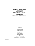
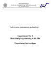
Note: Old 'USB Dongles' from previous versions cannot be used with this version. The version 2.0
Runtime can only be activated with a new version 2.0 USB Dongle which are clearly identified as
either ‘Machine Edition’ dongle or ‘PLUS’ dongle. A 'Machine Edition' dongle will only allow
projects compiled for 'Machine Edition' to run. A 'PLUS' dongle will allow both 'Machine Edition'
and 'PLUS' projects to run.
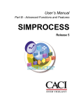
ActiveX
Machine
Edition
Yes
VBScript
Yes
Yes
Recipes
Yes
Yes
Alarms
300
5000
Animations
Yes
Yes
Max no. Devices
(PLCs etc.)
15
256
OPC Connections
Yes
Yes
Max user defined
Points
500
8000
Max Regular
Interval Scripts
10
100
Max no. Pages
100
500
MS Access
SQL, ODBC, MS
Access, MS Excel,
dBase, CSV
Feature
Supported
Databases
PLUS
Yes
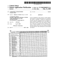
Activating a CX-Supervisor USB Dongle
The USB Dongle should not require any additional activation. The CX-Supervisor installation
process should correctly install and configure the required USB Dongle drivers, which should be
automatically loaded when the USB Dongle is fitted as above.
In exceptional circumstances, the CX-Supervisor USB Dongle Drivers can be
installed manually if required. The USB Dongle Driver installation shortcut can
be started from the Start button, and can be found under the Omron and CXSupervisor groups.
Revision 2.0
Page 5
Getting Started with CX-Supervisor
OMRON
Copy Protection using a Parallel Dongle
Old parallel port 'Hardlock Dongles' from previous versions cannot be used with this version. The
version 2.0 Runtime can only be activated with a new USB Dongle..
Copy Protection using a Software Token
Old 'Software Tokens' from previous versions cannot be used with this version. The version 2.0
Runtime can only be activated with a new USB Dongle.
Starting CX-Supervisor
After the software installation the Programs option from the Start button shows a new group window
for CX-Supervisor under the OMRON heading. The software is ready to run and can be started by
clicking on the CX-Supervisor Developer icon.
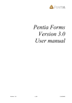
When CX-Supervisor Developer is started and a new Project created, it displays a window similar to
the one shown below. When launched automatically from the installation, the Engine demo is
automatically loaded, and by default when started thereafter the last loaded project is automatically
loaded. The CX-Supervisor window offers many features to ease the process of programming, using
the mouse or keyboard or both. It is possible to configure the display for any size monitor so that as
much or as little information is visible as required, using options from the View menu. Any display
configuration changes are saved in the Windows environment, and restored next time CX-Supervisor
is run.
Use this section to become familiar with the layout of the CX-Supervisor display, and to set it up as
desired.
Page 6
Revision 2.0
OMRON
Getting Started with CX-Supervisor
Customising CX-Supervisor Settings
By default CX-Supervisor shows the Workspace, Output view, Toolbar, Control bar and Status bar.
The display of these can be selected by activating the options from the View menu.
To display a toolbar, Window or the palette toolbox, click on the menu item with the mouse. A tick
next to a name indicates that it is currently displayed. CX-Supervisor saves the settings when it is
exited and restores them when it is next executed.
The CX-Supervisor Help System
CX-Supervisor comes with a detailed context-sensitive help system: at any time while using the
software, help can be obtained on the particular point currently being worked on, or on general
Revision 2.0
Page 7
Getting Started with CX-Supervisor
OMRON
aspects of CX-Supervisor. This system is intended to complement the manual, by providing on-line
reference to specific functions of the software and how to use them.
There are three types of CX-Supervisor help: index, context sensitive help and status bar help. An
index of help topics can be accessed at any time by clicking Index from the Help menu. Instructions
on how to use help can be accessed by clicking Using Help from the Help menu.
Alternatively, help on the topic currently in use can be obtained by pressing <F1>. Some dialogs also
provide a Help button.
At the bottom of the CX-Supervisor screen is a general status bar, which provides several helpful
pieces of information as the mouse is moved over display components.
CX-Supervisor also includes “point and click” help. To use this facility click on
the icon. The cursor changes to an arrow with a question mark next to it. Use
this cursor to point at any menu item or button on the display, and then click.
Context-sensitive help for that item is then displayed.
General information regarding CX-Supervisor can be obtained by selecting About CX-Supervisor
from the Help menu.
Page 8
Revision 2.0
OMRON
Basic Tutorial
Basic Tutorial
This chapter illustrates how to create a simple application using CX-Supervisor. It should only take about 20
minutes and should explain some key concepts:
•
The difference between the Development and Runtime applications.
•
The system is wholly controlled by data in the points, whether in memory or from a PLC
•
Controls can set the data
•
Graphical controls use Animations to control how the data is displayed
Introduction
This chapter describes how a simple traffic signal is drawn using the Graphics Editor and how it is
animated via the Animation Editor so that it changes colour − just as if it were a real traffic signal
controlling a road or rail junction.
As the first tutorial proceeds, important concepts about CX-Supervisor are introduced by this
symbol.
By the end of this tutorial, sufficient understanding of CX-Supervisor should have been gained to
allow progression to the second, more advanced tutorial which demonstrates some of the more
popular key features.
Note:
CX-Supervisor uses standard Microsoft Windows dialogs and conventions wherever
possible so that experienced Windows users should immediately feel comfortable.
Inexperienced Windows users should refer to standard Windows documentation.
The First Step
Before the tutorial can be started, the development version of CX-Supervisor must be installed on a
suitable machine, as described earlier in this manual. When this has been done, invoke CXSupervisor Development from the Start button.
When CX-Supervisor has initialised, the main screen is displayed as shown (or similar):
Revision 2.0
Page 9
Basic Tutorial
OMRON
The Concept of Projects
A project is the set of objects associated with one application. This includes Pages,
Graphics, Reports, Alarms, Animations, Point configuration, Point values, Recipes and all
other information.
Only one project can be opened by one application at a time.
A project must be created in which to conduct the tutorial; for simplicity, a separate sub-directory
should be created for each project.
1, 2, 3…
Page 10
Select New Project from the File menu and choose a Machine Edition project.
Revision 2.0
OMRON
Basic Tutorial
1.
Enter the project name as “Tutor”.
2.
Use the New Project Folder: field to determine the path to the new
project directory (for example, there could be a directory path similar
to “C:\Program Files\Omron\CX-Supervisor” on the machine).
3.
Specify the name of the new sub-directory that CX-Supervisor is to
create; for example, “tutorial”.
4.
Click on the OK button. A project called “tutor” and the specified subdirectory is created by CX-Supervisor. The project file is actually
called “tutor.scs”.
A blank page is displayed on the screen. If a blank page is not displayed, click on the New
Page button from the toolbar or select New Page from the File menu to create a new, blank
page.
CX-Supervisor Pages
A CX-Supervisor project usually consists of a number of separate pages. Each page
normally presents information relating to one particular topic, process, or activity. The
application designer uses the facilities of the graphics editor to draw and animate objects on
the page.
This tutor project consists of only one page.
Revision 2.0
Page 11
Basic Tutorial
OMRON
1, 2, 3…
1.
Name the page as “tutor.pag” using Save Page As from the File menu.
2.
Click on the Yes button when prompted to add the page to the project. The
page displayed on screen should still be empty.
Using the Graphics Editor
Now that the project exists with its own page, the graphic objects can be constructed and added to the
page.
The graphics editor uses a Graphic Object toolbar and a floating window known as the Palette to
construct and control objects on the page. These are very easy to use.
Several small icons are visible on the Graphic Object toolbar – each one representing one of the
graphical objects with which an application can be constructed. Some of the objects are graphical
Page 12
Revision 2.0
OMRON
Basic Tutorial
primitives – straight lines, ellipses, rectangles; some are rather more advanced – such as the gauge
object, which has built-in functionality.
Note:
The Graphic Object toolbar is only enabled when a page is active. If the toolbar looks
disabled, click the page to make it active.
On the Palette is a colour palette, line-style palette and fill-pattern palette. These selections control
the way in which objects appear.
Note:
The Palette can be hidden and shown using the View menu.
Experiment by creating examples of each of the various graphic objects at this stage and
configure with the Palette. When finished with these objects, delete them by clicking on
them and then hitting the <Delete> key or clicking on the Cut button from the toolbar.
1, 2, 3…
Revision 2.0
1.
Select the Select Mode button from the Graphic Object toolbar. Notice
that when the cursor is over an icon on the palette information about it is
displayed on the status bar. Similarly, if the cursor is left stationary over a
button then a tooltip message appears after a short while.
2.
Ensure that the selected colour from the palette is black, by clicking on the
colour black. Select the Round-Rectangle button from the Graphic Object
toolbar.
3.
Click the left mouse button and move the mouse pointer to near the top of
the page and drag the pointer downward. As this happens, the outline of a
round-rectangle appears on the screen to form the housing of the traffic
signal as shown below. Notice that the position, height and width of the
object being edited are displayed for reference on the status bar.
4.
Select the Rectangle button from the Graphic Object toolbar and draw the
support leg of the traffic signal.
Page 13
Basic Tutorial
OMRON
5.
Tip:
Now that the main structure of the traffic signal is complete (although
rather basic), work can begin on the coloured lights. Only two lights are
needed − one red and one green; this is best achieved by selecting the
Ellipse button from the Graphic Object toolbar and drawing a circle of
appropriate size to represent the light.
Holding the CTRL key down while drawing an ellipse ensures that a true circle is
drawn.
6.
Select the colour red and then position the light at the top of the traffic
signal.
7.
Repeat the process for the green light and position this at the bottom of the
traffic signal.
Adding a Point
Now we need to define a variable by which the traffic signal is to be controlled. As there are only 2
states i.e. ‘GO’ and ‘STOP’ a Boolean or digital value will be used.
Page 14
Revision 2.0
OMRON
Basic Tutorial
For simplicity of this tutorial this ‘Point’ or variable will be a local memory point. For a
real application of course we would be connecting to a PLC and reading a digital input.
Except for the following point definition the rest of this tutorial is identical to a real
monitoring application.
1, 2, 3…
Revision 2.0
1.
Click on the Point Editor button on the main toolbar. The Point
Editor window is displayed.
2.
Click on the Add Point button. The Add Point dialog is displayed.
3.
Now the variable, or ‘Point’, can be defined to control the traffic
signal; in this instance a simple Boolean point is used.
4.
At the Point Name field, type “GO”, as the name of the point.
5.
Check that the Point Type is “Boolean” and that “Memory” is selected
as the I/O Type.
6.
Click on the OK button. The point is added to the points database.
Page 15
Basic Tutorial
OMRON
Adding the toggle button
As this is a simulation to see the application in action we need a means of changing the value of our
new point “GO”. The simplest method is to use a “Toggle button”, a two-state button which changes
from one state to the other each time the button is pressed.
1, 2, 3…
1.
Select the Toggle Button from the Graphic Object toolbar and draw
out a button of a suitable size in relation to the traffic signal.
2.
Double-click on the newly-created Toggle button to bring up the
Toggle Button Wizard dialog.
3.
We will link the toggle operation to our new point. Click on the
Browse button and the Select Required Item dialog is displayed
4.
Select the new point ‘GO’ and click on the OK button.
5.
Click on the OK button on the Toggle Button Wizard dialog.
Animation
This simple traffic signal has only two states, ‘STOP’ and ‘GO’. If the signal is ‘STOP’, then the red
light must illuminate. If the signal is ‘GO’ the green light must illuminate. The Animation Editor is
the key to defining how an object is animated depending on point values. To configure the
animations:
1, 2, 3…
Page 16
1.
For simplicity first select the object that represents the Green light.
2.
Click on the Animation Editor button from the toolbar.
Revision 2.0
OMRON
Revision 2.0
Basic Tutorial
3.
There are a number of actions available for each particular object. With
suitable configuration, each of these actions may be applied to each object;
for example, the green light can be given the following actions:
Blink.
Close Page.
Colour Change, etc.
4.
By double-clicking the left mouse button, choose Colour Change (Digital).
By selecting this animation, CX-Supervisor is informed that the colour of
the Green light (an ellipse) is to be changed according to the value of some
Boolean (digital) variable or expression. The Colour Change dialog
appears:
5.
Now we will link this animation to our point. Click on the Browse button
on the Colour Change dialog. The Select Required Item dialog is
displayed.
6.
Select the new point ‘GO’ and click on the OK button.
Page 17
Basic Tutorial
OMRON
7.
In the Colour Change (Digital) dialog, ensure that “GO” is entered as the
digital expression.
8.
The Colour Change dialog shows the two colours between which the light
changes. The colours need to be selected so that when the traffic signal is
‘GO’, the Green light is bright-green (as per the default), but when it is
‘STOP’ i.e. State 0, the Green light dark-green or grey indicating the bulb
is not illuminated. The colours can be changed by clicking on the colour
preview box, and then using the Colour Palette dialog which subsequently
appears to choose the appropriate colour tones.
9.
The dialog should now look like this:
Click on the OK button.
The animation of the green light has now been defined.
The application should be tested to ensure that the light is operating correctly. Although the Red light
could also be animated at this stage, it is probably worth performing a runtime test on the tutor
application just to see how it operates.
Page 18
Revision 2.0
OMRON
Basic Tutorial
Testing the Project
Now the project can be tested in the runtime environment.
1, 2, 3…
1.
Click on the Run button from the toolbar. CX-Supervisor first saves the
current project and asks for confirmation to save the latest changes to
“tutor.pag”. Click on the Yes button.
2.
If this is the first time the page is saved, you will be prompted to add it to
the Project – select “Yes”.
3.
As there are no other pages to display, you will be prompted to Display the
page on Startup, select “Yes”.
4.
If you are prompted to save the project “Tutor.SCS”, select “Yes”.
5.
The runtime system starts with the page just created shown inside a frame
window.
6.
Click on the Toggle button and observe the button change state. The Green
light should change colour. When the button is clicked again, the Green
light should revert to its previous colour. Repeat this test a few more times
to observe the application in action. Notice that it really doesn’t matter
how quickly or slowly the button is selected; the light can always keep up
with the changes.
Be sure to check the colour of the Green light. Is it changing correctly between the two states? If
not, check the colour definitions back in the development environment.
Refining the Project
Any problems can be rectified by refining the project and re-running the application.
Revision 2.0
Page 19
Basic Tutorial
OMRON
1, 2, 3…
1.
Exit the Runtime environment by selecting Close from the Control menu,
or Right Clicking and selecting Exit from the popup menu.
2.
In the development environment, select the Green light and then bring up
the Animation Editor dialog.
3.
Once again, choose the Colour Change (Digital) dialog. The two colours
are shown at the bottom of the dialog. If necessary, select the colour and
change its tone by using the Colour Palette dialog.
4.
Now select the Red light and animate this in the same manner as for the
Green light. Remember that with the traffic signal, the red light needs to be
‘ON’ i.e. bright-red when ‘GO’ is false i.e. State 0. When ‘GO’ is true i.e.
State 1 the Red light should be dark-red or grey indicating the bulb is not
illuminated.
Now try runtime once again. Click on the Run button from the toolbar and try out the new
tutor application; this time both lights should change colour as the button is selected. If both
lights go on and off together then check, and possibly, change the colour definitions as
described above.
Otherwise the traffic signal should be working as expected - changing from red to green as the button
is pressed. On alternate selections, the signal should change back from green to red.
Page 20
Revision 2.0
OMRON
Basic Tutorial
Admittedly this application is very simple, but it demonstrates some key points for all your
applications:
•
The difference between the Development and Runtime applications.
•
The system is wholly controlled by data in the points, whether in memory or from a
PLC
•
Controls (like the Toggle button) can set the data
•
Graphical controls use Animations to control how the data is displayed
This concludes the Basic Tutorial and you have learnt a little about Projects, Pages, Graphical
objects, Points, Animations and running projects.
Revision 2.0
Page 21
Basic Tutorial
Page 22
OMRON
Revision 2.0
OMRON
Advanced Tutorial
Advanced Tutorial
This chapter introduces some of the more advanced topics of CX-Supervisor. It is expected the user is
already familiar with:
•
General Windows operation
•
Software installation
•
Creating, opening, saving and running of CX-Supervisor projects.
•
Creating and saving pages
•
Adding graphical objects and animations
This chapter is intended to be a quick guide to the topics, not full step-by-step instructions. For a full
description of these areas refer to the related chapters in the User Manual.
Coffee Machine scenario
This tutorial is going to take the form of a simulation of a coffee vending machine. They all have a familiar
User Interface, display functions, control functions and we will be adding alarm, recipe and security functions.
Again this tutorial will use Memory points for simplicity, but remember with minimal changes the application
could easily be monitoring and controlling a real PLC.
STEP 01 - GETTING STARTED
Follow the steps outlined, referring if necessary to the User Manual for specific instructions.
1, 2, 3…
1.
Create a new Machine Edition Project with the following specifications:
Project Name = COFFEE
Project Description = Coffee Vending Machine
Project Directory = C:\COFFEE
2.
Create a new page from the File menu. Save the created page as
“Open.pag” into the project directory, C:\COFFEE
3.
Make sure the page is added to the project, if not add it
4.
Run the application and test if the page is displayed correctly
STEP 02 – PROJECT EDITOR
Revision 2.0
Page 23
Advanced Tutorial
1, 2, 3…
OMRON
1.
Create a new page from the File menu
2.
Save the new page and name it “Main.pag”
3.
Using the Workspace, right click Main.pag to make it Display on Run and
make Open.pag not Display on Run by removing the tick.
STEP 03 – GRAPHICS PAGES
1, 2, 3…
1.
Open open.pag
2.
Double click the page to set the following properties:
Page Title = Open
Border Style = THICK
Display Mode = REPLACE
Top = 0
Left = 0
Height = 582
Width = 800
Background colour = Yellow
The dialog should now look as follows:
Page 24
Revision 2.0
OMRON
Advanced Tutorial
3.
Repeat for Main.pag with the following properties:
Page Title = Main
Border Style = THICK
Display Mode = REPLACE
Top = 0
Left = 0
Height = 582
Width = 800
Background colour = Yellow
4.
Revision 2.0
Still on Main.pag, draw a 3D floor using different graphics objects from
the graphics object toolbox. Use a line object, and 2 Polygons. Use the
colour Palette to change the fill patterns and colours. The page should now
look like this
Page 25
Advanced Tutorial
OMRON
Now draw the Coffee machine as shown in the picture below
1.
Use a Text object from the Graphics Toolbar for the display, and another
for the 2 digit selection code. Use hash ‘#’ characters to signify space to be
replaced with a value.
2.
Use 10 Push Buttons for the user selection buttons, with text 0 to 9
respectively
3.
Add a menu showing the selection numbers for the different drinks, both
with and without sugar
Tip: You can use Copy and Paste to quickly duplicate similar items
Tip: You can use the Alignment toolbar (or View Menu, Alignment) to quickly
align all selected objects horizontally or vertically
The page should now resemble the following:
Page 26
Revision 2.0
OMRON
Advanced Tutorial
4.
On the upper right corner, include new Push Buttons for displaying
different pages for later exercises. Label the buttons Alarms, Graphs &
Charts, Data Logging, File Handling, Report Generation, Database and
Security.
STEP 04 – GRAPHICS LIBRARY
Now we’ll add these to a Graphics Library for later re-use.
1, 2, 3…
1.
Select the objects used for the background. Holding the Shift key allows
selected objects to be added to the selection.
2.
Group the objects together by pressing <Ctrl>+G or selecting Group from
the Edit menu, and rename the group object to Background
3.
Select all the objects in the coffee machine by dragging the selection box
around all the objects.
4.
Group the objects together. Rename the group object to CoffeeMachine
5.
Open the Graphics Library Editor window, and position so both can be
clearly seen.
6.
Add a library called My Library
7.
Add the grouped objects to your new library by just dragging them from the
page to the Library Window. Note that object animations and scripts are
copied to the Library.
Now we’ll re-use these objects.
Revision 2.0
Page 27
Advanced Tutorial
1, 2, 3…
OMRON
1.
Open the page “open.pag”.
2.
Open the Graphics Library Editor window, and position so both can be
clearly seen.
3.
Drag the Background and Coffee Machine to the new page.
4.
Modify the page to show the machine open, as shown below.
•
Delete the menu objects
•
Add the open door
•
Add storage tanks (from the TANKS_16 library)
•
Add Push buttons under the tanks
Tip: You can also use Copy and Paste to quickly create duplicate objects like
the tanks and buttons.
Page 28
Revision 2.0
OMRON
Advanced Tutorial
STEP 05 – ANIMATION
We have 2 pages but the application still doesn’t actually do anything. Now we’ll add the points and
animations to make the machine function.
Add the required points.
1, 2, 3…
Point name
coffee_level
credit
displaytext
milk_level
selection
sugar_level
tea_level
time_counter
water_level
1.
Ensure the project is saved before continuing
2.
From the toolbar open the Point Editor (or Utilities Menu, Point Editor)
3.
Add the points required for this step with details as listed in the table
below. The Description column is optional as it only helps explain to you
the function of the point.
Point type
Integer
Boolean
Text
Integer
Integer
Integer
Integer
Integer
Integer
Default Value
2000
Description (optional)
Total level of stored coffee
TRUE when coin inserted into the machine
**************** Top line of machine display
2000
Total level of stored milk
Number of selection made
2000
Total level of stored sugar
2000
Total level of stored tea
Control pouring of drink
2000
Total level of stored water
Opening and closing the machine:
Revision 2.0
Page 29
Advanced Tutorial
1, 2, 3…
OMRON
1.
Open the page called open
2.
Select the door lock object on the bottom left
3.
From the toolbar, open the Animation Editor (or Utilities Menu,
animation Editor)
4.
Add an animation for Display Page and select the page to be opened as
Main. Note that because the pages were defined as Replace, when one
page opens it will replace (and close) pages underneath automatically.
5.
Repeat for the door lock on the page called Main to open the page called
Open
1.
Open the page called Main
2.
Select the coin and add an animation for Execute Script with the script
code “credit = 1” to acknowledge that money has been entered.
3.
Also add an animation for Visibility controlled by the value of credit.
Remember the coin should be visible while credit is false, or should be
invisible when credit is true or “credit == 1”
Inserting the coin:
1, 2, 3…
Updating displays, and pouring coffee:
1, 2, 3…
1.
Select the main display object
2.
Add a Display Value (Text) animation to with an expression displaytext.
Note: if this animation is not available then the object may not have been
originally created as a Text Object type.
3.
Add a Display Value (Analogue) animation to the 2 digit display with an
expression selection
4.
Add a Resize (Height) animation to coffee liquid object with an expression
time_counter to simulate the pouring. Minimum and Maximum should be
0 and 50 respectively.
Displaying storage levels:
Page 30
Revision 2.0
OMRON
Advanced Tutorial
1, 2, 3…
1.
Open the page called open
2.
Select the storage tank for the coffee. Use the Workspace or Ungroup to
find the rectangular window and add a Percentage Fill (Vertical)
animation to the coffee storage tank viewing window with an expression
coffee_level and minimum and maximum of 0 and 2000 respectively
3.
Repeat for the other storage tanks with the appropriate points for the
expressions.
4.
Add an Edit Value (Analogue) animation to the button below the coffee
tank with an expression coffee_level
5.
Repeat for each button using appropriate point for each level
Now would be a good time to run the application by clicking the toolbar button “Run the project” (or
Project Menu, Run) and test that you can open and close the machine, and add credit to the machine.
STEP 06 – SCRIPTS
To extend the functionality we will add a Reset() subroutine for initializing, make the coffee liquid and the
cup invisible and set a text such as “Insert coin” for the coffee machine display. This assumes the cup object,
pouring coffee and main display objects are called cup, coffee and Text_2 respectively. Either adjust the
script for your object names, or rename them in the Workspace to these values.
Add the points required by this step.
1, 2, 3…
Point name
pressed
ready
selection_made
Revision 2.0
1.
Open the Point Editor
2.
Add the points with details as listed in the table below. The Description
column is optional as it only helps explain to you the function of the point.
Point type Default Value
Boolean
Boolean
Boolean
Description (optional)
TRUE once first digit has been pressed
Machine is ready to make a drink
TRUE when a selection has been made
Page 31
Advanced Tutorial
1, 2, 3…
OMRON
1.
Open the Workspace editor
2.
Right click on Project Script to add a new Project Script
3.
Set Trigger Event of Subroutine named Reset with the following script
code to reset variables:
4.
credit = 0
selection = 0
ready = TRUE
pressed = false
selection_made = false
main.coffee.visible(0)
main.cup.visible(0)
displaytext = "Insert Coin"
main.Text_2.blink( black )
On Main.pag add a Page Script with a Trigger Event of On Initialisation
to execute every time the page is loaded with the following code:
CALL Reset( )
When the coin is inserted, we want to make a sound and change the displayed command.
1, 2, 3…
1.
Copy the sound file cashreg.wav from the folder of the sample programs to
the project folder C:\Coffee
2.
Create a Page Script with Trigger Event of On Condition with an
Expression of credit == 1 and script code of :
displaytext = "Make a Selection"
PlaySound("c:\coffee\cashreg.wav")
Include a script for displaying the user selection in the Selection Display and assign this selection to the
selection variable. Use the variables selection to store the number typed, pressed to note when the first digit
has been entered and selection_made to determine when the second digit has been entered therefore the
selection is complete.
Page 32
Revision 2.0
OMRON
Advanced Tutorial
1, 2, 3…
1.
Add a Execute Script animation to the Push Button with caption “1” with
the following code:
IF pressed == TRUE THEN
selection = (selection * 10 ) + 1
pressed = FALSE
selection_made = TRUE
ELSE
selection = 1
pressed = TRUE
selection_made = FALSE
ENDIF
2.
Repeat for the other buttons, replacing both the 1’s with the appropriate
digit.
To round off this step, include a script to produce the selection entered by the user. This script should:
- Display a message for informing the user what is happening
- Display the cup and the coffee liquid.
- Play a sound file to simulate the coffee dropping, and one when finished
- Display a message to notify the user to pick up the coffee
1, 2, 3…
1.
Copy the sound files glu.wav and finished.wav from the folder of the
sample programs to the project folder C:\Coffee
2.
Add a page script to trigger On Condition called Make the Drink with an
expression of “(selection_made == TRUE) and (credit == 1) and (ready
== TRUE)”. Add the following code:
ready = FALSE
displaytext = "Making your selection"
cup.visible( 1)
coffee.visible (1)
for time_counter = 0 to 50
'just looping for coffee animation
next
PlaySound("c:\coffee\glu.wav")
PlaySound("c:\coffee\glu.wav")
PlaySound("c:\coffee\glu.wav")
PlaySound("c:\coffee\glu.wav")
Sleep(2000)
coffee.visible(0)
PlaySound("c:\coffee\finished.wav")
displaytext = "Pick up your selection"
Revision 2.0
Page 33
Advanced Tutorial
OMRON
3.
Add an Execute Script animation to coffee cup with code to call the Reset
subroutine when the cup is clicked.
Now’s a good time to run the application and test the changes so far.
STEP 07 – RECIPES
So we can buy, select and make a drink, but how do we handle making different types of drinks? By creating a
‘Recipe’ for each choice, predetermined amounts of ingredients can be used.
Add the points required by this step.
Point name
aux_text
coffee_amount
milk_amount
selection_name
sugar_amount
tea_amount
water_amount
Point type Default Value
Text
Integer
Integer
Text
Integer
Integer
Integer
1, 2, 3…
Description (optional)
Temporary text area for conversions
Amount of coffee for this selection
Amount of milk for this selection
Name of selection made
Amount of sugar for this selection
Amount of tea for this selection
Amount of water for this selection
1.
Open the Recipe Editor.
2.
Create a new recipe called “11” and add the following ingredients. Note
that for simplicity the Recipe name is made the same as the selection code.
Ingredient 1
Ingredient 2
Ingredient 3
Ingredient 4
Ingredient 5
Ingredient 6
3.
Ingredient Name
Name
Coffee
Water
Sugar
Milk
Tea
Point
selection_name
coffee_amount
water_amount
sugar_amount
milk_amount
tea_amount
Quantity
Black Coffee
100
100
0
0
0
Create remaining recipes with ingredient quantities as detailed in the list
below.
Tip: You can Copy and Paste Recipe 11 and the recipe name will automatically
be incremented. The Ingredient values may then just be edited.
Page 34
Revision 2.0
OMRON
Advanced Tutorial
Recipe
Name
12
13
14
15
16
Name
Coffee
Water
Sugar
Milk
Tea
Espresso
White
Coffee
Milk
Tea
Water
50
50
75
50
0
0
0
50
0
0
0
0
0
0
100
100
0
0
0
100
0
0
0
100
0
4.
Copy all the previous recipes for the remaining selections (21, 22, 23, 24,
25, 26) and change the sugar ingredient to 50, and name with a “with
Sugar” suffix.
5.
Add the code to the Make the Drink script to download the recipe
ingredients :
aux_text = ValueToText( selection )
DownloadRecipe (aux_text)
Sleep( 1000)
'Take quantities from storage
coffee_level = coffee_level - coffee_amount
water_level = water_level - water_amount
milk_level = milk_level - milk_amount
tea_level = tea_level - tea_amount
sugar_level = sugar_level - sugar_amount
When run, you will see that each time a drink is made the storage tanks are emptied by the correct amount for
each ingredient.
STEP 08 – ALARMS
We can provide the mechanism to create an alarm should any of the resources run out.
1, 2, 3…
Revision 2.0
1.
Open the Alarm Editor.
2.
Add the alarms with details from the list below.
Page 35
Advanced Tutorial
Name
coffee_level_alarm
water_level_alarm
milk_level_alarm
tea_level_alarm
sugar_level_alarm
OMRON
Expression
coffee_level <= 0
water_level <= 0
milk_level <= 0
tea_level < = 0
sugar_level <= 0
Raised Message
Coffee deposit is empty
Water deposit is empty
Milk deposit is empty
Tea deposit is empty
Sugar deposit is empty
Normal Message
Coffee deposit is refilled
Water deposit is refilled
Milk deposit is refilled
Tea deposit is refilled
Sugar deposit is refilled
Test the alarms to see them in action.
Add Alarm viewing page:
1, 2, 3…
1.
Make a new page with the following properties and save it to the project
folder.
Page Title = Alarm
Border Style = THICK
Display Mode = POPUP
Top = 0
Left = 505
Height = 582
Width = 295
2.
Use the Workspace to remove the Display On Run option from the popup
menu.
3.
Add an ‘Alarm’ Graphical Object for displaying alarms in real time.
Configure the object as you wish.
4.
Add a button with text “Alarm Status Viewer” and add script code:
DisplayAlarmStatus()
5.
Add a button with text “Alarm History Log” and add script code:
DisplayAlarmHistory()
6.
Add a ‘Close’ button with an animation to close the page.
7.
Open Main page and add an animation to the “Alarms” button to display
the new page called Alarm.
This concludes the section on alarms. Test out your application then move on to the next step.
STEP 9 – GRAPHS AND CHARTS
Real-time data can be graphically represented on Bar Charts and trend graphs.
Page 36
Revision 2.0
OMRON
Advanced Tutorial
Add the points required by this step.
Point name
Point type Default Value
milk_temperature
Integer
70
water_temperature Integer
80
1, 2, 3…
Description (optional)
Temperature of milk (degrees C)
Temperature of water (degrees C)
1.
Make a new page with the following properties and save it to the project
folder.
Page Title = Graphs
Border Style = THICK
Display Mode = POPUP
Top = 0
Left = 505
Height = 582
Width = 295
2.
Add a ‘Chart’ Graphical Object for displaying alarms in real time.
Configure the object to graph the 5 resource levels (coffee_level etc), with
appropriate labels
3.
Use the Workspace to remove the Display On Run option from the popup
menu.
4.
Add a ‘Trend Graph’ Graphical Object for displaying water_temperature
and milk_temperature. Configure as preferred, scaling from 0 to 200.
5.
Add 2 sliders and link to water_temperature and milk_temperature to
simulate changing temperatures.
6.
Add a ‘Close’ button with an animation to close the page.
7.
Open Main page and add an animation to the “Graphs & Charts” button to
display the new page called Graphs.
STEP 10 – DATA LOGGING
In addition to simple trending, we can add comprehensive Data Logging. First create the items to log.
Revision 2.0
Page 37
Advanced Tutorial
1, 2, 3…
OMRON
1.
Open the Workspace Editor and select the Data Logging tab
2.
Right click and select Add DataSet…
3.
Right click on the added Data Set and select Add Item…. Add the item
Milk Temperature and enter milk_temperature in the expression field.
4.
Repeat to add an item called Water Temperature for point
water_temperature.
Then create a page to view and export the data and control logging:
1, 2, 3…
1.
Make a new page with the following properties
Page Title = Datalog
Border Style = THICK
Display Mode = POPUP
Top = 0
Left = 505
Height = 582
Width = 295
2.
Use the Workspace to remove the Display On Run option from the popup
menu.
3.
Add a button to automatically open the data log viewer using the command
“OpenLogView("Dataset1", "Milk Temperature,Water
Temperature", "")”
4.
Add a button to export data to CSV using the command
“ExportLog("Dataset1", "Milk Temperature,Water Temperature",
"CSV", 0, "c:\coffee\export.txt")”
5.
Add a button to manually restart logging using the command
“StartLogging("Dataset1")”
6.
Add a button to manually restart logging using the command
“StopLogging("Dataset1")”
7.
Add a ‘Close’ button with an animation to close the page.
8.
Open Main page and add an animation to the “Data Logging” button to
display the new page called Datalog.
STEP 11 – FILE HANDLING
Page 38
Revision 2.0
OMRON
Advanced Tutorial
We’ll add a file handling page allowing the selected drink to be written to a file on disk. The file format will
look like this:
03:42:52 10/30/2002 – User Selection: 14
03:44:28 10/30/2002 – User Selection: 22
03:53:28 10/31/2002 – User Selection: 16
First add the points required by this step.
Point name
aux_text2
fileindex
filename
ret
Point type Default Value
Text
Integer
Text
Integer
Description (optional)
Temporary text area for conversions
Index to current position in text file
Name of text file to read from.
General purpose 'return' value from various script
functions
Then write the subroutine to do the work. This subroutine should be called every time a drink is made.
1, 2, 3…
1.
At the Project level, add a subroutine script called WriteToDisk
2.
Add an integer parameter called sel
3.
Add code to format the data and write to disk:
aux_text2 = ValueToText( selection )
aux_text = $Time + " "+ $Date+ " - User selection: "+aux_text2
ret = WriteMessage("selections.txt", -1, aux_text, true)
4.
Add script code to Make the Drink script to call the new subroutine
Add the detail to the File Handling page:
Revision 2.0
Page 39
Advanced Tutorial
1, 2, 3…
OMRON
1.
Make a new page with the following properties
Page Title = File
Border Style = THICK
Display Mode = POPUP
Top = 0
Left = 505
Height = 582
Width = 295
2.
Use the Workspace to remove the Display On Run option from the popup
menu.
3.
Add a button with caption Select File with the following script for selecting
the previously created file (selections.txt):
filename = SelectFile("Text Files (*.txt)|*.txt|All Files (*.*)|*.*||",
"C:\Coffee")
4.
Add a button with caption Line Read with the following script for reading
a line of text from the selected file:
aux_text = ""
ReadMessage(filename, fileindex, aux_text, 42)
fileindex = fileindex + 42
5.
Add a button with caption Reset Index with the following script for
resetting the cursor to the start of the file:
fileindex = 0
6.
Add 3 Text objects with Display animations to display the points filename,
aux_text, and fileindex.
7.
Add a ‘Close’ button with an animation to close the page.
8.
Open Main page and add an animation to the “File Handling” button to
display the new page called File.
STEP 12 – REPORT GENERATION
Data can easily be formatted and exported in a textual report, for example in .TXT, .RTF or .HTML format.
The template file will contain the following text:
DEPOSIT LEVEL REPORT
(("DATE: %s", $Date ))
Page 40
Revision 2.0
OMRON
Advanced Tutorial
(("TIME: %s", $Time ))
(("Coffee Level: %d", coffee_level))
(("Water Level: %d", water_level))
(("Milk Level: %d", milk_level))
(("Tea Level: %d", tea_level))
(("Sugar Level: %d", sugar_level))
(("Active Alarms: %d", $ActiveAlarms))
1, 2, 3…
1.
Create a file in the project directory called source.txt with the template
text. This template will be evaluated and the values within brackets
formatted at runtime.
2.
Make a new page with the following properties
Page Title = Report
Border Style = THICK
Display Mode = POPUP
Top = 0
Left = 505
Height = 582
Width = 295
3.
Use the Workspace to remove the Display On Run option from the popup
menu.
4.
Add a button with caption Generate Report with the following script for
creating the output report file (report.txt):
GenerateReport("C:\coffee\source.txt","report.txt")
5.
Add a button with caption View Report with the following script for
launching an associated viewer:
ViewReport("C:\coffee\report.txt")
6.
Add a button with caption Edit Report with the following script for
loading the template into an installed editor:
EditFile("C:\coffee\source.txt")
Revision 2.0
7.
Add a ‘Close’ button with an animation to close the page.
8.
Open Main page and add an animation to the “Report Generation” button
to display the new page called Report.
Page 41
Advanced Tutorial
OMRON
Creating HTML reports:
1, 2, 3…
1.
Create a file in the project directory called source.htm with the template
text. If using Word or more powerful html editor, feel free to experiment
with different fonts, font sizes and colours etc.
2.
Add 3 buttons to Generate, View and Edit the report as per the text
example.
STEP 13 – DATABASE ACCESS
We will add the facility to write the ingredients used to a standard database, and add a page to read through
records previously written. First we must create the database template using Microsoft Access. Please consult
your Microsoft documentation for full details of these operations. If you do not have Microsoft Access, you
can still read and write Access files from CX-Supervisor but you will need to copy a database file from the
demo folder to use as a template. Alternatively you can use any other ADO compatible data source, with
suitable changes to the connection details.
Add the point required by this step.
Point name
record_index
Point type Default Value
Integer
1, 2, 3…
Field Name
Selection
Page 42
Description (optional)
Index to current database record
1.
Launch Microsoft Access and create a new database called coffee.mdb in
the project directory C:\Coffee
2.
Create a new table, in Design View if prompted.
3.
Insert 6 new Fields and rename them as per the table below.
4.
Open the table Design, and configure the data type and field size from the
table below.
5.
Save the table as Ingredients, without an index if prompted
6.
Close Microsoft Access, saving any changes.
Field Data Type
Memo
Field Size
-
Revision 2.0
OMRON
Advanced Tutorial
Coffee
Water
Milk
Tea
Sugar
Number
Number
Number
Number
Number
Integer
Integer
Integer
Integer
Integer
You should now have a template Access database (or other) to use. The next step is to add the database
connections in the Developer.
1, 2, 3…
1.
Open CX-Supervisor Developer and load the project.
2.
Open the Workspace and switch to the Database tab
3.
Right click and add a new connection called Connection1 and specify the
new template file C:\Coffee\coffee.mdb as the Data Source.
4.
Right click the Connection and select Connect. The icon will change to
indicate the connection is live.
5.
Add a new Recordset for adding records, called Recordset1 to the
connection and ensure Ingredients is selected as the table name for the
Source. To allow writing to the database make sure Pessimistic (or
Optimistic) lock is selected.
6.
Add a Field called selection linked to point selection_made and Field
Selection. Change the Field Property to Add.
7.
Repeat to add coffee linked to point coffee_amount and Field coffee with
the Field Property Add and repeat for milk, sugar, tea, and water.
8.
Add a new Recordset for reading records, called Recordset2 to the
connection and ensure Ingredients is selected as the table name for the
Source.
9.
Copy each field from Recordset1 and Paste to Recordset2. Change all the
Field Properties from Add to Value.
With the template of the database now defined, it is very to easy write the data to the database
Revision 2.0
Page 43
Advanced Tutorial
OMRON
1, 2, 3…
1.
At the Project level, add a subroutine script called WriteToDatabase
2.
Add code to write to the database, requery the table so that the latest data
can be seen, and navigate back to the original record:
DBAddNew( "Connection1.Recordset1" )
DBExecute( "Connection1.Recordset2", "Requery" )
DBMove( "Connection1.Recordset2", "Position", record_index)
3.
Add script code to Make the Drink script to call the new subroutine
Written database records can now be viewed:
1, 2, 3…
1.
At the Project level, add a subroutine script called ReadFromDatabase
2.
Add code to read to the database:
DBRead( "Connection1.Recordset2" )
record_index = DBProperty( "Connection1.Recordset2",
"CurrentRecord" )
3.
Make a new page with the following properties
Page Title = Database
Border Style = THICK
Display Mode = POPUP
Top = 0
Left = 505
Height = 582
Width = 295
4.
Use the Workspace to remove the Display On Run option from the popup
menu.
5.
Add a button for navigating to the next record with the script:
ret = DBProperty( "Connection1.Recordset2", "RecordCount" )
IF record_index < ret THEN
DBMove( "Connection1.Recordset2", "Next" )
ENDIF
CALL ReadFromDatabase( )
6.
Add a button for navigating to the previous record with the script:
DBMove( "Connection1.Recordset2", "Previous" )
CALL ReadFromDatabase( )
7.
Page 44
Add a Text object with a Display animation to display the point
record_index.
Revision 2.0
OMRON
Advanced Tutorial
8.
Add 6 Text objects with Display animations to display the points
selection_made,
coffee_amount,
water_amount,
milk_amount,
tea_amount, and sugar_amount.
9.
Add a ‘Close’ button with an animation to close the page.
10. Open Main page and add an animation to the “Database” button to display
the new page called Database.
STEP 14 – SECURITY
Operations can be restricted to users with acceptable security privileges. We will only allow Supervisors or
those with higher privileges to open the machine.
1, 2, 3…
1.
Open the Main page
2.
Select the door lock on the bottom left of the machine.
3.
Open the Animation Editor and select the Display Page action previously
added. On the toolbar, change the Security Level for this operation from
All Users to Supervisor.
4.
Add an Execute Script animation with the following code:
IF $SecurityLevel < 2 THEN
Message( "You are not authorized to open the machine")
ENDIF
Revision 2.0
Page 45
Advanced Tutorial
OMRON
And add a page to control the security
1, 2, 3…
1.
Make a new page with the following properties
Page Title = Security
Border Style = THICK
Display Mode = POPUP
Top = 0
Left = 505
Height = 582
Width = 295
2.
Use the Workspace to remove the Display On Run option from the popup
menu.
3.
Add 2 buttons with captions Login and Logout and add code to call script
functions (just “Login()” and “Logout()” respectively).
4.
If you desire, add Text objects with Display animations to display the
points $SecurityLevel, $SecurityName, and $UserName.
5.
Add a ‘Close’ button with an animation to close the page.
6.
Open Main page and add an animation to the “Security” button to display
the new page called Security.
You can now test the security. Note the default user names and passwords below are case sensitive:
User
Operator
Supervisor
Manager
Designer
Password
Operator
Supervisor
Manager
Designer
This concludes the Advanced tutorial where you have learnt about Graphics Libraries, Recipes, more
animations, different scripts, Alarms, Graphs and Charts, Data Logging, File handling, Report generation,
Database connectivity, and Security. These topics have only been touched on briefly, to show some basic
possibilities and are further detailed in the User Manual and Script Reference manual.
The final solution will have been installed and can be run from the Start button, in Demos under the CXSupervisor folder.
Page 46
Revision 2.0
OMRON
GLOSSARY
GLOSSARY
ADO
ADO stands for ActiveX Data Objects and is data access technology which
uses OLE-DB to access data sources in a uniform way e.g. MS-Access
databases, MS-Excel spreadsheets and Comma Separated Variable files.
Application
A software program that accomplishes a specific task. Examples of
applications are CX-Supervisor, CX-Programmer, Microsoft Word for
Windows and Microsoft Excel. CX-Supervisor and its development
environment allows the creation and testing of new applications through a
Graphical User Interface (GUI).
Bitmap
The representation of an image stored in a computer’s memory. Each
picture element (pixel) is represented by bits stored in the memory. In CXSupervisor a bitmap image can be installed as a single object.
Communications Driver
The relevant communications management system for OMRON PLCs in
conjunction with Microsoft Windows, providing facilities for other CX
Automation Suite software to maintain PLC device and address
information and to communicate with OMRON PLCs and their supported
network types.
CX-Supervisor
A software application which creates and maintains graphical user
interfaces and communicates with PLCs and other I/O mechanisms.
DDE
Dynamic Data Exchange. An obsolete Microsoft technology which
provides a channel through which correctly prepared programs can actively
exchange data and control other applications within Microsoft Windows.
Development environment
Applications are created using the development environment within CXSupervisor. On completion, the finished application can be delivered as a
final customer application to be run by the run-time environment.
Dongle
A hardware key that plugs in the USB port that unlocks operation.
GUI
Graphical User Interface. Part of a program that interacts with the user and
takes full advantage of the graphics displays of computers. A GUI
employs pull-down menus and dialog boxes for ease of use. Like all
Microsoft Windows based applications, CX-Supervisor has a GUI.
I/O type
Input / Output type. An attribute of a point that defines the origin and
destination of the data for that point. The data for a point can originate (be
input from) and is destined (is output to) to the internal computer memory,
PLC, DDE target application.
Revision 2.0
Page 47
GLOSSARY
OMRON
Icon
Pictorial representations of computer resources and functions. The CXSupervisor development environment and run-time environment are run
from icons. Icons are also used in CX-Supervisor to indicate an OLE
object.
Microsoft Excel
A spread sheet application.
Microsoft Windows
A windowing environment for personal computers, that is noted for its
GUI, and for features such as multiple typefaces, desk accessories (such as
a clock, calculator, calendar and notepad), and the capability of moving
text and graphics from one application to another via a clipboard.
CX-Supervisor will run only under Microsoft Windows.
Microsoft Word
A word processing application.
See also SVGA mode and VGA mode.
Object
In CX-Supervisor, an object can be text, graphics, a control, a bitmap, or
OLE object as created in the development environment. A complex object
can exist as a combination of two or more objects of any of the above
types. Specifically, graphical objects can be categorised as a line, an arc, a
polygon (including a square and rectangle), a round rectangle, an ellipse
(including a circle), or a Polyline. A control is essentially a complex
graphic object and is specifically either a button, a toggle button, a slider, a
trend graph, a rotational gauge or a linear gauge.
OLE
Object Linking and Embedding. Used to transfer and share information
between Microsoft Windows based applications and accessories. When
OLE is used in CX-Supervisor, it is possible to view or even edit a file
from a target application.
OLE-DB
OLE-DB is the underlying database technology, on which ADO relies.
OLE-BD is designed to be the successor to ODBC.
Operator
A symbol used as a function, with infix syntax if it has two arguments (e.g.
“+”) or prefix syntax if it has only one argument (e.g. NOT). The CXSupervisor script language uses operators for built-in functions such as
arithmetic and logic.
Pages
The combination and manipulation of pages containing objects within
projects forms the basis of CX-Supervisor. More than one page can exist
for each project. The pages in a project provide the visual aspect of CXSupervisor corresponding to a display with the objects contained in each
page providing a graphical representation of the system being monitored.
Page 48
Revision 2.0
OMRON
GLOSSARY
Pixel
A single displayable point on the screen from which a displayed image is
constructed. The screen resolution of the computer’s Visual Display Unit
(VDU) is defined by the number of pixels across and the number of pixels
down (e.g. 1024 x 768).
PLC
Programmable Logic Controller.
Point
A point is used to hold a value of a predefined type - Boolean, Integer,
Text, etc. The contents of a point may be controlled by an object or I/O
mechanism such as DDE. The contents of a point may control the action
or appearance of an object, or be used for output via an I/O mechanism.
Project
A CX-Supervisor application will consist of one or a number of pages
linked together. The pages may contain passive or active graphics, text or
animations, and may be grouped together logically to form a project. A
project may consist of many pages, or simply a single page. Projects may
be built and tested within the CX-Supervisor development environment,
and run stand-alone under the CX-Supervisor run-time environment.
Only one project at a time may be open for editing within the CXSupervisor development environment.
Run Time Environment
Applications are run using the run-time environment of CX-Supervisor,
following creation of the application in the CX-Supervisor development
environment.
SCADA
Supervisory Control and Data Acquisition.
SVGA mode
A mode of video display that provides 800 × 600 pixel resolution (or
higher) with 16 or more colours and is supported on Super Video Graphics
Adapter systems.
Topic
Within the CX-Supervisor script language, Topic is used in DDE functions
to specify a file name pertaining to an outside application. Using DDE
functions, CX-Supervisor allows the opening of a file, part of the server
application.
VGA mode
A mode of video display that provides 640 × 480 pixel resolution with 16
colours and is supported on Video Graphics Adapter systems.
Windows Desktop
An integral part of Microsoft Windows which allows Microsoft Windows
based applications to be started from icons and for all applications to be
organised. CX-Supervisor can be run from Windows Desktop.
Revision 2.0
Page 49
GLOSSARY
Page 50
OMRON
Revision 2.0
OMRON
INDEX – Getting Started
INDEX
Activating · 6
Fitting · 5
A
Dynamic Data Exchange · 49
About this Manual · 2
Accessing the Help System · 9
Activating a Dongle · 6
Activating CX-Supervisor Token · 6
F
Fitting a Dongle · 5
ActiveX Data Objects · 49
Adding a Point - Tutorial
Advanced - Tutorial
Animation - Tutorial
G
Animations · 16–20
Application · 49
Getting Started · 1, 11
B
Graphical User Interface · 49
Graphics Editor · 14–16
View · 12
Bitmaps · 49
H
C
Hardware Communication Interface · 4
Hardware Copy Protection · See Dongle. See Dongle
Hardware Requirements · 3
Help System · 9
Communications Driver · 49
Concepts of Projects - Tutorial
Copy Protection · 4
Backing up Token Diskettes · 8
Disk Cache Operation · 7
Disk Compression · 7
Disk Defragmentors · 8
File Maintenance · 7
Protection using a Token · 4
Restrictions · 7
System Backup · See
Token Installation · 7
Customising Settings · 9
CX-Supervisor · 49
CX-Supervisor Pages - Tutorial
D
HTML reports · 44
I
Icon · 50
Input / Output Types · 49
Installing CX-Supervisor · 4
Interfaces to Hardware · 4
Introduction to CX-Supervisor · 1, 11
M
Microsoft Excel · 50
Microsoft Windows · 50
Development Environment · 49
Dongle · 5
Revision 2.0
Page 51
INDEX – Getting Started
O
Object · 50
Object Linking Embedding (OLE) · 50
Operating Systems and Environments · 3
Operator · 50
P
Pages · 50
Pixel · 51
Point · 51
Point Editor
Create point · 20
Project · 51
Concepts · 12–13
Creating a new project · 12
R
Refining Projects- Tutorial
Run Time Environment · 51
Runtime
Testing · 11, 20, 21, 23
S
SCADA · 51
Settings - Customising CX-Supervisor · 9
Simple Tutorial · 12–22
Software Copy Protection · 4
Using a Token · 6
Starting CX-Supervisor · 1, 8, 11
System Requirements · 3
Hardware Requirements · 3
Interfaces to Hardware · 4
Operating System · 3
T
Testing the Project - Tutorial
Page 52
OMRON
The First Steps with CX-Supervisor · 11
Token
Activating a Token · 6
Backing up Token Diskettes · 8
Copy Protection · 6
Disk Cache Operation · 7
Disk Compression · 7
Disk Defragmenters · 8
File Maintenance · 7
Installing a Token · 7
Restrictions · 7
System Backup · 7
Topic · 51
Tutorial
Adding a Point · 16, 17
Advanced · 25
Alarms · 37
Animation · 18, 31
Charts · 38
Concepts of Projects · 12
CX-Supervisor Pages · 13
Data Logging · 39
Database access · 44
File Handling · 40
Graphics Editor · 14
Graphics Library · 29
Graphs · 38
HTML Reports · 42
Reading Files · 40
Recipes · 36
Refining the Project · 21
Report Generation · 42
Scripts · 33
Security · 47
Simple · 12–22
Testing the Project · 20
U
Using a Token for copy protection · 6
Using the Graphics Editor- Tutorial
V
VGA Mode · 51
Revision 2.0
OMRON
W
Revision 2.0
INDEX – Getting Started
Welcome to CX-Supervisor · 1
Windows Desktop · 51
Page 53
Terms and Conditions of Sale
1. Offer; Acceptance. These terms and conditions (these "Terms") are deemed
part of all quotes, agreements, purchase orders, acknowledgments, price lists,
catalogs, manuals, brochures and other documents, whether electronic or in
writing, relating to the sale of products or services (collectively, the "Products")
by Omron Electronics LLC and its subsidiary companies (“Omron”). Omron
objects to any terms or conditions proposed in Buyer’s purchase order or other
documents which are inconsistent with, or in addition to, these Terms.
2. Prices; Payment Terms. All prices stated are current, subject to change without notice by Omron. Omron reserves the right to increase or decrease prices
on any unshipped portions of outstanding orders. Payments for Products are
due net 30 days unless otherwise stated in the invoice.
3. Discounts. Cash discounts, if any, will apply only on the net amount of invoices
sent to Buyer after deducting transportation charges, taxes and duties, and will
be allowed only if (i) the invoice is paid according to Omron’s payment terms
and (ii) Buyer has no past due amounts.
4. Interest. Omron, at its option, may charge Buyer 1-1/2% interest per month or
the maximum legal rate, whichever is less, on any balance not paid within the
stated terms.
5. Orders. Omron will accept no order less than $200 net billing.
6. Governmental Approvals. Buyer shall be responsible for, and shall bear all
costs involved in, obtaining any government approvals required for the importation or sale of the Products.
7. Taxes. All taxes, duties and other governmental charges (other than general
real property and income taxes), including any interest or penalties thereon,
imposed directly or indirectly on Omron or required to be collected directly or
indirectly by Omron for the manufacture, production, sale, delivery, importation, consumption or use of the Products sold hereunder (including customs
duties and sales, excise, use, turnover and license taxes) shall be charged to
and remitted by Buyer to Omron.
8. Financial. If the financial position of Buyer at any time becomes unsatisfactory
to Omron, Omron reserves the right to stop shipments or require satisfactory
security or payment in advance. If Buyer fails to make payment or otherwise
comply with these Terms or any related agreement, Omron may (without liability and in addition to other remedies) cancel any unshipped portion of Products sold hereunder and stop any Products in transit until Buyer pays all
amounts, including amounts payable hereunder, whether or not then due,
which are owing to it by Buyer. Buyer shall in any event remain liable for all
unpaid accounts.
9. Cancellation; Etc. Orders are not subject to rescheduling or cancellation
unless Buyer indemnifies Omron against all related costs or expenses.
10. Force Majeure. Omron shall not be liable for any delay or failure in delivery
resulting from causes beyond its control, including earthquakes, fires, floods,
strikes or other labor disputes, shortage of labor or materials, accidents to
machinery, acts of sabotage, riots, delay in or lack of transportation or the
requirements of any government authority.
11. Shipping; Delivery. Unless otherwise expressly agreed in writing by Omron:
a. Shipments shall be by a carrier selected by Omron; Omron will not drop ship
except in “break down” situations.
b. Such carrier shall act as the agent of Buyer and delivery to such carrier shall
constitute delivery to Buyer;
c. All sales and shipments of Products shall be FOB shipping point (unless otherwise stated in writing by Omron), at which point title and risk of loss shall
pass from Omron to Buyer; provided that Omron shall retain a security interest in the Products until the full purchase price is paid;
d. Delivery and shipping dates are estimates only; and
e. Omron will package Products as it deems proper for protection against normal handling and extra charges apply to special conditions.
12. Claims. Any claim by Buyer against Omron for shortage or damage to the
Products occurring before delivery to the carrier must be presented in writing
to Omron within 30 days of receipt of shipment and include the original transportation bill signed by the carrier noting that the carrier received the Products
from Omron in the condition claimed.
13. Warranties. (a) Exclusive Warranty. Omron’s exclusive warranty is that the
Products will be free from defects in materials and workmanship for a period of
twelve months from the date of sale by Omron (or such other period expressed
in writing by Omron). Omron disclaims all other warranties, express or implied.
(b) Limitations. OMRON MAKES NO WARRANTY OR REPRESENTATION,
EXPRESS OR IMPLIED, ABOUT NON-INFRINGEMENT, MERCHANTABIL-
14.
15.
16.
17.
18.
ITY OR FITNESS FOR A PARTICULAR PURPOSE OF THE PRODUCTS.
BUYER ACKNOWLEDGES THAT IT ALONE HAS DETERMINED THAT THE
PRODUCTS WILL SUITABLY MEET THE REQUIREMENTS OF THEIR
INTENDED USE. Omron further disclaims all warranties and responsibility of
any type for claims or expenses based on infringement by the Products or otherwise of any intellectual property right. (c) Buyer Remedy. Omron’s sole obligation hereunder shall be, at Omron’s election, to (i) replace (in the form
originally shipped with Buyer responsible for labor charges for removal or
replacement thereof) the non-complying Product, (ii) repair the non-complying
Product, or (iii) repay or credit Buyer an amount equal to the purchase price of
the non-complying Product; provided that in no event shall Omron be responsible for warranty, repair, indemnity or any other claims or expenses regarding
the Products unless Omron’s analysis confirms that the Products were properly handled, stored, installed and maintained and not subject to contamination, abuse, misuse or inappropriate modification. Return of any Products by
Buyer must be approved in writing by Omron before shipment. Omron Companies shall not be liable for the suitability or unsuitability or the results from the
use of Products in combination with any electrical or electronic components,
circuits, system assemblies or any other materials or substances or environments. Any advice, recommendations or information given orally or in writing,
are not to be construed as an amendment or addition to the above warranty.
See http://www.omron247.com or contact your Omron representative for published information.
Limitation on Liability; Etc. OMRON COMPANIES SHALL NOT BE LIABLE
FOR SPECIAL, INDIRECT, INCIDENTAL, OR CONSEQUENTIAL DAMAGES,
LOSS OF PROFITS OR PRODUCTION OR COMMERCIAL LOSS IN ANY
WAY CONNECTED WITH THE PRODUCTS, WHETHER SUCH CLAIM IS
BASED IN CONTRACT, WARRANTY, NEGLIGENCE OR STRICT LIABILITY.
Further, in no event shall liability of Omron Companies exceed the individual
price of the Product on which liability is asserted.
Indemnities. Buyer shall indemnify and hold harmless Omron Companies and
their employees from and against all liabilities, losses, claims, costs and
expenses (including attorney's fees and expenses) related to any claim, investigation, litigation or proceeding (whether or not Omron is a party) which arises
or is alleged to arise from Buyer's acts or omissions under these Terms or in
any way with respect to the Products. Without limiting the foregoing, Buyer (at
its own expense) shall indemnify and hold harmless Omron and defend or settle any action brought against such Companies to the extent based on a claim
that any Product made to Buyer specifications infringed intellectual property
rights of another party.
Property; Confidentiality. Any intellectual property in the Products is the exclusive property of Omron Companies and Buyer shall not attempt to duplicate it
in any way without the written permission of Omron. Notwithstanding any
charges to Buyer for engineering or tooling, all engineering and tooling shall
remain the exclusive property of Omron. All information and materials supplied
by Omron to Buyer relating to the Products are confidential and proprietary,
and Buyer shall limit distribution thereof to its trusted employees and strictly
prevent disclosure to any third party.
Export Controls. Buyer shall comply with all applicable laws, regulations and
licenses regarding (i) export of products or information; (iii) sale of products to
“forbidden” or other proscribed persons; and (ii) disclosure to non-citizens of
regulated technology or information.
Miscellaneous. (a) Waiver. No failure or delay by Omron in exercising any right
and no course of dealing between Buyer and Omron shall operate as a waiver
of rights by Omron. (b) Assignment. Buyer may not assign its rights hereunder
without Omron's written consent. (c) Law. These Terms are governed by the
law of the jurisdiction of the home office of the Omron company from which
Buyer is purchasing the Products (without regard to conflict of law principles). (d) Amendment. These Terms constitute the entire agreement between
Buyer and Omron relating to the Products, and no provision may be changed
or waived unless in writing signed by the parties. (e) Severability. If any provision hereof is rendered ineffective or invalid, such provision shall not invalidate
any other provision. (f) Setoff. Buyer shall have no right to set off any amounts
against the amount owing in respect of this invoice. (g) Definitions. As used
herein, “including” means “including without limitation”; and “Omron Companies” (or similar words) mean Omron Corporation and any direct or indirect
subsidiary or affiliate thereof.
Certain Precautions on Specifications and Use
1. Suitability of Use. Omron Companies shall not be responsible for conformity
with any standards, codes or regulations which apply to the combination of the
Product in the Buyer’s application or use of the Product. At Buyer’s request,
Omron will provide applicable third party certification documents identifying
ratings and limitations of use which apply to the Product. This information by
itself is not sufficient for a complete determination of the suitability of the Product in combination with the end product, machine, system, or other application
or use. Buyer shall be solely responsible for determining appropriateness of
the particular Product with respect to Buyer’s application, product or system.
Buyer shall take application responsibility in all cases but the following is a
non-exhaustive list of applications for which particular attention must be given:
(i) Outdoor use, uses involving potential chemical contamination or electrical
interference, or conditions or uses not described in this document.
(ii) Use in consumer products or any use in significant quantities.
(iii) Energy control systems, combustion systems, railroad systems, aviation
systems, medical equipment, amusement machines, vehicles, safety equipment, and installations subject to separate industry or government regulations.
(iv) Systems, machines and equipment that could present a risk to life or property. Please know and observe all prohibitions of use applicable to this Product.
NEVER USE THE PRODUCT FOR AN APPLICATION INVOLVING SERIOUS
RISK TO LIFE OR PROPERTY OR IN LARGE QUANTITIES WITHOUT
ENSURING THAT THE SYSTEM AS A WHOLE HAS BEEN DESIGNED TO
2.
3.
4.
5.
ADDRESS THE RISKS, AND THAT THE OMRON’S PRODUCT IS PROPERLY RATED AND INSTALLED FOR THE INTENDED USE WITHIN THE
OVERALL EQUIPMENT OR SYSTEM.
Programmable Products. Omron Companies shall not be responsible for the
user’s programming of a programmable Product, or any consequence thereof.
Performance Data. Data presented in Omron Company websites, catalogs
and other materials is provided as a guide for the user in determining suitability and does not constitute a warranty. It may represent the result of Omron’s
test conditions, and the user must correlate it to actual application requirements. Actual performance is subject to the Omron’s Warranty and Limitations
of Liability.
Change in Specifications. Product specifications and accessories may be
changed at any time based on improvements and other reasons. It is our practice to change part numbers when published ratings or features are changed,
or when significant construction changes are made. However, some specifications of the Product may be changed without any notice. When in doubt, special part numbers may be assigned to fix or establish key specifications for
your application. Please consult with your Omron’s representative at any time
to confirm actual specifications of purchased Product.
Errors and Omissions. Information presented by Omron Companies has been
checked and is believed to be accurate; however, no responsibility is assumed
for clerical, typographical or proofreading errors or omissions.
OMRON ELECTRONICS LLC • THE AMERICAS HEADQUARTERS
Schaumburg, IL USA • 847.843.7900 • 800.556.6766 • www.omron247.com
OMRON CANADA, INC. • HEAD OFFICE
OMRON ARGENTINA • SALES OFFICE
Toronto, ON, Canada • 416.286.6465 • 866.986.6766 • www.omron.ca
Cono Sur • 54.11.4787.1129
OMRON ELETRÔNICA DO BRASIL LTDA • HEAD OFFICE
OMRON CHILE • SALES OFFICE
São Paulo, SP, Brasil • 55.11.2101.6300 • www.omron.com.br
Santiago 56.2206.4592
OMRON ELECTRONICS MEXICO SA DE CV • HEAD OFFICE
OTHER OMRON LATIN AMERICA SALES
Apodaca, N.L. • 52.811.156.99.10 • [email protected]
56.2206.4592
W08E-EN-01
Note: Specifications are subject to change.
© 2008 Omron Electronics LLC
Printed in U.S.A.