1
Bulletin No. 80445-109-01A
January 2001
Model 6 OMNI-Center Enhanced
List of Figures
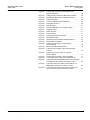
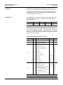
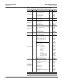
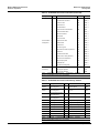
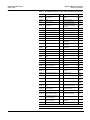
Figure 43:
Figure 44:
Figure 45:
Figure 46:
Figure 47:
Figure 48:
Figure 49:
Figure 50:
Figure 51:
Figure 52:
Figure 53:
Figure 54:
Figure 55:
Figure 56:
Figure 57:
Figure 58:
Figure 59:
Figure 60:
Figure 61:
Figure 62:
Figure 63:
Figure 64:
Figure 65:
Figure 66:
© 2001 Schneider Electric All Rights Reserved
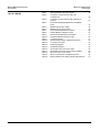
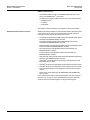
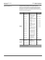
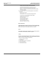
Power Leads and Top of Terminal Blocks Fed
through Wiring Port . . . . . . . . . . . . . . . . . . . . . . . . . . . . . . . 68
Pulling the Twin Handle Cam Mechanism Forward . . . . . . 69
Operating the Mechanism-to-Structure Interlock . . . . . . . . 69
Locked Out Device . . . . . . . . . . . . . . . . . . . . . . . . . . . . . . . 69
Control Unit Bottom Plate Folded Down. . . . . . . . . . . . . . . 69
Driving Out Hinge Pin. . . . . . . . . . . . . . . . . . . . . . . . . . . . . 69
Stab Assembly . . . . . . . . . . . . . . . . . . . . . . . . . . . . . . . . . . 70
Operator Mechanism in the Tripped Position . . . . . . . . . . . 71
Inspecting Fuses . . . . . . . . . . . . . . . . . . . . . . . . . . . . . . . . 71
Starter Contacts . . . . . . . . . . . . . . . . . . . . . . . . . . . . . . . . . 71
Control Devices . . . . . . . . . . . . . . . . . . . . . . . . . . . . . . . . . 71
Tightening Electrical Connections . . . . . . . . . . . . . . . . . . . 71
Manual Bus Shutter . . . . . . . . . . . . . . . . . . . . . . . . . . . . . . 72
Operating the Door Interlock Defeat Mechanism . . . . . . . . 73
Shelf and Door Installation . . . . . . . . . . . . . . . . . . . . . . . . . 76
Cutting the Vertical Wire Trough Grommet
(when supplied) . . . . . . . . . . . . . . . . . . . . . . . . . . . . . . . . . . 76
Removing the Manual Bus Shutter. . . . . . . . . . . . . . . . . . . 76
Pulling the Twin Handles of the Cam Mechanism
Forward . . . . . . . . . . . . . . . . . . . . . . . . . . . . . . . . . . . . . . . . 76
Tightening the Control Unit Lock-in Device
(when supplied) . . . . . . . . . . . . . . . . . . . . . . . . . . . . . . . . . 77
Power Leads Connected to Power Terminals . . . . . . . . . . 77
Connecting Control Leads to the Terminal Blocks . . . . . . . 77
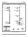
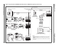
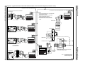
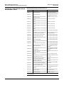
Typical Schematic for MODBUS PLUS Communications
to a MODICON PLC System (not drawn to scale) . . . . . . . . 83
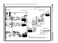
Typical Schematic for Profibus Communication to a
MODICON PLC System (not drawn to scale) . . . . . . . . . . . 85
Typical Schematic for DeviceNet Communications to
an SLC-500 PLC System (not drawn to scale). . . . . . . . . . . 87
7