1
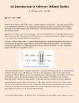
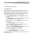
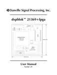
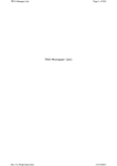
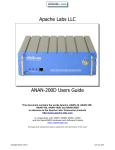
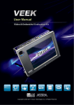
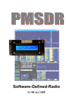
OpenHPSDR for VHF/UHF/Microwave, version 2.0
by Roger Rehr W3SZ
I. Introduction The first presentation that I gave on the use of DSP techniques in Amateur Radio was
fourteen years ago, in 2001. At that time I presented at the NEWS Conference a talk on the use of DSP
techniques in Amateur weak signal work, titled “A Brief Discussion of Some Software DSP Solutions
I've Tried”. I did not use the term “Software Defined Radio” once. The software I discussed included
Brian Beezley K6STI's DSP Blaster, Leif Asbrink SM5BSZ's MS-DOS PC-Receiver, which Leif was
just porting to Linux at that time, and which had not yet received the name “Linrad”, Bob Larkin
W7PUA's DSP-10 hardware and software, and Spectran, by I2PHD and IK2CZL. Gerald
Youngblood's now famous 4-part QEX series titled “A Software-Defined Radio for the Masses” had
not yet appeared, but would be published in the second half of 2002 and early 2003. The first Flex
Radio product, the SDR-1000, would appear in 2003, two years after the talk I gave here.
A lot has changed since then! Software defined radios are now used by experimenter and appliance
operator alike. There are SDRs with knobs (e.g. Elecraft KX3) and SDRs without knobs. There are
SDRs usable by the appliance operator (e.g. Elecraft KX3, FlexRadios) and those more suited for the
experimenter (openHPSDR projects). Although I was able to cover the totality of the DSP solutions
available to the Amateur Radio operator in 2001 in one paper, that is no longer possible. In this paper I
will focus on the openHPSDR project, or High Performance Software Defined Radio project, as these
are the radios that I use at W3SZ. The openHPSDR project was originally called just “HPSDR”, but
for a variety of reasons not germane to my discussion today, the project is now officially termed the
“openHPSDR” project.
I have previously presented talks and papers detailing the great importance of having full-time
bandscopes for VHF/UHF/Microwave work (including a talk at this conference in 2012, where I
presented the first iteration of my openHPSDR VHF/UHF/microwave controller), and hopefully
everyone reading this is convinced of the necessity of having full-time bandscopes on each of the bands
through 432 or 903 or 1296 MHz (I won't argue the small point of where the cutoff lies), with an
additional bandscope for 2.3 GHz (or 903 MHz or 1296 MHz) and up. The reader is referred to prior
presentations in this paper and in this paper and at this link if he/she remains in doubt on this point.
II. History of openHPSDR In 2005, Phil Covington started the High Performance SDR (HPSDR)
project, using a motherboard with an FPGA and a USB 2.0 interface. Around the same time, Phil
Harman (then VK6APH and now VK6PH) and Bill Tracey, KD5TFD developed a sound card
replacement for the SDR-1000, also using a motherboard with an FPGA and a USB 2.0 interface. This
was the XYLO SDR group. These groups merged in early 2006, and HPSDR.org was created. Phil
Covington developed the ATLAS backplane and the OZY board, to replace the XYLO board. He then
developed the Quick Silver board, which was the initial prototype for the Mercury receiver board.
Mercury development began in 2006 and continued through 2007, with Phil Harman VK6PH acting as
project leader. In March, 2008 TAPR agreed to fund the Mercury development proposal. Since that
time TAPR has continued to provide development funding for the openHPSDR hardware, and the
openHPSDR hardware has been available for purchase on the TAPR website. Additional sources of the
openHPSDR hardware have included Gerd Loch of Loch Leiterplatten GmbH, and more recently,
Apache Labs, owned and managed by “Abhi”, Abhishek Arunoday Prakas, who was the primary PCB
layout team member for Hermes. I recommend that you peruse both the TAPR website at
http://www.tapr.org/hpsdr_index.html and the Apache Labs website at https://apache-labs.com/ if you
are interested in purchasing openHPSDR hardware. To get a more complete view of the openHPSDR
project than I can provide here, refer to the openHPSDR website at http://openhpsdr.org/
III. First Generation Architecture The initial openHPSDR architecture was that of a common
backplane into which various plug-in boards were connected. The graphic below, taken from the
openHPSDR website (openhpsdr.org), gives further detail:
In the graphic above you can see the Atlas backplane running vertically on the left of the graphic. Atlas
can accommodate up to 6 daughter boards. At the top, connected to Atlas, is a communication board,
connecting the openHPSDR hardware to a computer. Ozy was the first such board, and it connected to
the computer by USB. Magister was an updated version of Ozy. Metis is the most recently released
communications board, connecting the openHPSDR hardware to the computer via Ethernet. Moving
down the Atlas bus, we see next Mercury. Mercury is the Direct DownConversion (DDC) receiver.
Alex optionally connects to Mercury to provide filters. I do not use Alex for my VHF and up work, as
it is not necessary for this purpose. Next in line is a transmitter board. Penelope was the first Direct
UpConversion (DUC) transmitter produced by this project; Pennylane is a newer version. Either of
these transmitters optionally connects to an amplifier and the Alex filters. Next in line is Excalibur,
which is an optional time standard board, with optional external 10 MHz input for GSP locking. Janus
was a sound interface card, which is no longer needed. Finally, LPU is a linear power supply that takes
13.8 VDC in and supplies appropriate voltages to the Atlas-connected boards. An enclosure box, named
Pandora, is available for this system. Pandora measures approximately 12 x 9 x 5.5 inches.
My current station uses this Atlas backplane model for all of its radios, although I do have some
Hermes radios that I will discuss below, and by the time you read this some of them may have been
incorporated into my system. Below is a picture of Pandora with 4 installed daughter cards. I took this
image from the openHPSDR website, as I was too lazy to open up one of my Pandora boxes to show
the insides.
The board in the foreground is the LPU power supply. The next board is the DDC receiver Mercury,
the board above that is the DUC transmitter Penelope, the board above that is the USB computer
interface board Ozy, and the hardware enclosed in the aluminum case at the very top of the picture with
ribbon cable coming out the back is Alex, the set of HF filters. The board sitting behind the Pandora
with a large heat sink visible below the circuit board is the PennyWhistle 160-6 meter amplifier, which
will deliver 16-20 watts output with 250 mW drive supplied by either Penelope or Pennylane.
Here is a picture of the Atlas backplane with its 6 board slots:
The Excalibur GPS-disciplined 10 MHz source is below:
The Mercury DDC Receiver is shown below:
Below is the Penelope DUC transmitter.
IV. Second Generation Architecture In 2009 it was decided that a single board transceiver would be
the next openHPSDR project. It was to be named Hermes. The Mercury transmitter and Penelope
receiver code were successfully placed into one FPGA in 2009, and in 2010 it was decided to add an
Ethernet interface to the board. By mid 2012 the Hermes boards were available for purchase on the
TAPR website, and on October 1, 2012 Hermes became available from the Apache Labs website as
well.
A block diagram of Hermes is below, taken from the openHPSDR Hermes Wiki page:
Both Hermes and the earlier Atlas/Penelope/Mercury hardware provide transceive capability covering
approximately 0-55 MHz. Published performance Specifications include:
Blocking Dynamic Range: no detectable gain compression below ADC overload
Dynamic Range 125 dB
Image Rejection > 110 dB
Full Duplex
Transmitter two-tone 3rd order IMD -50 dBc @ 400 mW output
500 mW RF output on 160 – 10 m amateur bands, 350 mW on 6 m
Noise Floor -135 dBm in 500 Hz
Seven user-configurable open collector outputs
Separate open collector PTT connection
Stereo outputs at line level and headphone level
Low phase noise master clock (-140 dBc/Hz @ 1 kHz at 14 MHz)
Hermes board size 160 mm x 120 mm (8 layers)
Below is a picture of the Hermes board, taken from the Hermes User Manual, version 1.18.
On the right edge near the top are two gold SMA connectors, used for RF out and RF in. Below that is
the 1 Watt audio amplifier output. Below that is the edge connector with 26 pins for PTT, line level
stereo audio in and out, stereo headphone out, 3 digital inputs, 2 analog inputs, 7 open collector
outputs, speaker output, and several ground connections. The gold SMA connector at the bottom of the
right edge is for 10 MHz in, in case GPS locking is desired.
On the left edge, the top connector is for microphone in. The next connector is for headphone, and the
third and last connector in that triad is for CW key/keyer.
Below that on the left edge is the RJ45 Ethernet connector.
Below is an illustration of a Hermes board that I've placed in an ANAN-10 case, sitting on top of a
Pandora box, so you can get some idea of the relative sizes of these two units.
V. Apache Labs As was noted above, “Abhi”, Abhishek Arunoday Prakash, founded and owns and
manages Apache Labs. Apache's current openHPSDR-related products include the ANAN-10E, the
ANAN-10, the ANAN-100, the ANAN-100D, the ANAN-200D, and the Angelia. All of these radios
have receive coverage from 10 kHz through 55 MHz and transmit coverage of the Amateur bands from
160 through 6 meters. The Angelia has a maximum RF output of 500 mW. The ANAN-10E and the
ANAN-10 have a maximum RF output of 10 Watts, and the other ANAN radios have a maximum RF
output of 100 watts. The Angelia is a special purpose product, with dual phase-locked receive channels
suitable for diversity reception. The ANAN-10E and the ANAN-100 permit up to 4 receivers, and the
ANAN-10, ANAN-100D and the ANAN-200D permit up to 7 receivers. The ANAN-10E uses a 14 bit
ADC, while the other radios all use 16 bit ADCs. The ANAN-10E uses an EP3C25 FPGA. The 10 and
the 100 use the larger EP3C40 FPGA, whereas the 100D uses an even larger EP4CE115, and the 200D
uses the still-larger EP4CGX150. The 10 and the 100 have 16 MB of FLASH RAM, and the 100D and
200D have 128 MB. The 100D and the 200D each have 32 Mbit of SRAM; the 10 and the 100 have
none. A spreadsheet comparing several of the different ANAN models is here. Apache Labs also sells
the Hermes board, which is no longer available from TAPR.
VI. Hermes-Lite There is currently an openHPSDR interest group led by Steve Haynal, KF7O that is
working on a cheaper version of Hermes, called Hermes-Lite. The main differences between the units
are [1] Hermes-Lite uses a 12 bit ADC rather than a 16 bit ADC, thus reducing digital dynamic range,
[2] Hermes-Lite uses a BeMicro SDK FPGA board instead of an onboard FPGA, [3] the Hermes-Lite
will cover 0-30 MHz rather than 0-55 MHz. Anticipated cost for those who build their own is $150 or
less. There is a GitHub project page for Hermes-Lite at https://github.com/softerhardware/Hermes-Lite
VII. Hermes VNA. Both Phil Harman (VK6PH) and Alex Shovkoplyas (VE3NEA) have written
software that will turn the Hermes transceiver into a Vector Network Analyzer (VNA). An executable
for Phil's software is available on the openHPSDR downloads page. The source code is available here,
and as of the time of this writing the executable that is obtained by compiling this source code is newer
and has better function than the executable file on the openHPSDR page. Alex's VNA software is
called Ham VNA and is available here.
VII. Receiver and Transceiver Software. The most full-featured and most widely used software for
the openHPSDR radios is PowerSDR, which started with source code modified primarily by Bill
Tracey (KD5TFD) and Doug Wigley (W5WC) from the FlexRadio PowerSDR software. PowerSDR is
written using Microsoft's C# (C Sharp) programming language, and runs on Windows. Power SDR has
been very actively maintained by Doug, with Warren Pratt (NR0V) making major contributions
including replacing the original DttSP DSP code with his wdsp library and adding a new and novel
noise blanker to name just a couple of his many contributions. PowerSDR (and the other software
discussed in this section) can be downloaded from the openHPSDR downloads page.
There is also cuSDR, which requires NVIDIA CUDA hardware and, as of the time of the writing of this
paper, remains receive only. Like PowerSDR, cuSDR is Windows-based. GHPSDR and GNURADIOHPSDR are other available software packages for the openHPSDR hardware, and both provide
transceive capability.
The final piece of generally available software that we will discuss here is KISS Konsole, which also
provides transceive capability. It was developed by Phil Harman (VK6PH) as a simpler alternative to
PowerSDR, suitable for experimentation and exploration by HPSDR users. I have used it as the basis
for the software that I have developed for my VHF/UHF/Microwave station and which I will discuss
below. KISS Konsole is windows-based and is written in C# (C Sharp), although in mid 2014 Jae
Stutzman (K5JAE) reported porting KISS Konsole to Linux, using the Mono Development Kit.
The ability for "users" to play with the code contained in KISS Konsole and PowerSDR was
substantially increased when Microsoft decided to make the complete Visual Studio IDE (Integrated
Development Environment) available as a free download in 2014. Previously, only limited versions of
the Visual Studio software had been available at no cost. Currently Visual Studio Community 2013 is
the most recent version, although Visual Studio Community 2015 is due to be released sometime soon.
You may read about and download Visual Studio Community 2013 here.
If you are serious about programming with Visual Studio, then you should also install NuGet, which is
a package manager for the Microsoft development platform. With NuGet you will gain access to many
third party addons to Visual Studio. You can download NuGet from here.
VIII. My Modified KISS Konsole Software Project. In 2012 I presented at the combined
PackRats/NEWSGroup VHF/UHF/Microwave Conference a paper titled, "What's All This Multiple
Bandscope Stuff, Anyhow?". At that time I described the software and hardware that I had built to give
me "always on" bandscopes on 50, 144, 222, 432, and 1296 MHz, with an additional always on
bandscope that was shared among 903 MHz and 2, 3, 5, 10, and 24 GHz. That system has worked very
well for me over the years. The station control GUI actually consisted of several interlocking software
pieces, which is a less elegant solution than would be a solution consisting of only a single program.
Additionally, because my solution used multiple instances of VNC (Virtual Network Computing), one
for each radio, this solution was not as efficient as it might be in terms of network utilization, although
I never experienced any network issues, due to the fact that I carefully chose the VNC parameters to
minimize network resource utilization. The illustration below, although simplified, gives some idea of
the complexity of this earlier solution. Each green-colored box represents a different piece of software
written by me for this earlier project:
My primary goals with the current project that I describe in this paper were four. The first goal was to
implement the entire Control system as a single program that would seamlessly connect with the
N1MM+ logging program, and be seen by N1MM+ as a single radio covering all bands from 50 MHz
through 24 GHz. The second goal was to reduce substantially the network bandwidth required for
communication between the individual radio/SDR servers and the SDR Controller software. The third
goal was to eliminate the need for a Hardware Controller. The fourth goal was to provide the capability
for remote operation from a computer not co-located with the radios, by means of either a wired or
wireless Ethernet connection.
I had to run my previous system on a Mac Pro Dual Quad Core with Apple's Gigabit network interface,
as I needed this horsepower in order to achieve adequate bandwidth for the multiple incoming VNC
instances. At the time I put that system together, Apple's Ethernet performance was far better than that
available with any easily available Windows-based hardware. I was very successful in reducing both
the network bandwidth required and CPU utilization with the new software, even though the new
software provides for simultaneous streaming of receive audio from two SDRs to the client computer in
addition to seven full time bandscopes, radio control, etc. The network bandwidth of the new system is
is on the order of 0.5% of a 100 Mbps bandwidth connection, that is, on the order of only 500 kbps.
Running on a 3.6 GHz Intel I3 4160, the current system gives approximately 25-30% CPU utilization.
The block diagram of the new system is below.
You can see that the controller now consists of only one program, labeled C Sharp SDR Controller, that
interfaces with N1MM + and the individual SDRs and their C Sharp SDR Servers. The link with
N1MM is via virtual serial ports, and the link with the radios is via a wired or wireless Ethernet link,
using UDP packets.
To create the new SDR Controller, I basically wrote two new pieces of software, both derived from the
KISS Konsole model. One piece is a server that is directly connected to the openHPSDR radio
hardware, and that does the DSP processing and radio control. This server software runs on a
"headless" computer with no video monitor, keyboard, or mouse, and the operator has no direct
communications with that computer / software. All communications are through the second piece of
software. Also, there are no physical connections to the SDR server or its associated radio hardware
for microphone audio input, CW key input, PTT input, or receive audio output. All of these
connections are made via the Ethernet.
The second piece of software is the C Sharp SDR Controller shown in the block diagram above. The C
Sharp SDR Controller software is the user interface, and is located on the logging computer at which
the operator sits. That computer can be located either at the radio site or remotely, as long as there is an
Ethernet connection available. This SDR Controller accepts input from the user, either directly or via
N1MM, and it is responsible for all communications with the individual radio/server units, and for
assigning footswitches, microphone, CW key/keyer, receive audio, and transverters to the appropriate
IF radio automatically with no need for user intervention. The CW key, microphone, and footswitches
are all connected to this computer.
I also did retain the ability to use the Hardware SDR Controller with this system, but I am not currently
using it.
To describe the project in list form:
In the first iteration of this software, before I eliminated the need for the Hardware SDR Controller, the
basic VK6PH KISS Konsole Software attributes/functions that were retained in my new Server module
included:
1. Connects directly to the radio [via Ethernet]
2. Receives baseband receive IQ data from the radio
3. Receives mic input from the radio
4. Receives key input from the radio
5. Receives PTT input from the radio
6. Sends commands to the radio
7. Sends processed receive audio back to the radio
8. Sends transmit IQ data back to radio
However, with the elimination of the need for the Hardware SDR Controller, the functions of the server
change substantially (only 1 and 2 are unchanged):
1. Connects directly to the radio [via Ethernet]
2. Receives baseband receive IQ data from the radio
3. Receives mic input via the Ethernet from the client and sends appropriate IQ data to the radio
4. Receives key input via the Ethernet from the client and sends appropriate IQ data to the radio
5. Receives PTT input via the Ethernet from the client and forwards to the radio
6. Receives commands from the client and forwards these commands to the radio if appropriate
7. Sends processed receive audio to the client
8. Microwave server receives band information from client and sends band information to N3FTI
bandswitch
Other major changes/additions that I made to KISS Konsole when I created the Server module were:
1. Adds capability for server to receive commands from client software, so that server and radio can be
controlled remotely by the client software.
2. Adds adjustable FFT Size for Spectrum and Waterfall. There was previously only one small FFT
size that was "hardwired in". This is not acceptable for weak signal work. FFT size is now adjustable
from 4096 to 524288. To do this I had to split the audio FFT processing from the graphic FFT
processing, and I used FFTW and the C# wrapper for it named FFTWSharp. I had to extend the
FFTSharp dll to implement Wisdom. That is described near the bottom of this page.
3. Adds CW sidetone using default computer sound playback device. Because C# does not have audio
support, I used the CSCore C# wrapper for Windows audio functions for this.
4. Adds receive audio using default computer sound playback device. Previously there was receive
audio available only at the openHPSDR hardware. Although receive audio was created in the computer
from IQ data, it was sent back to the radio and could not previously be listened to through the
computer. Because C# does not have audio support, I used the CSCore C# wrapper for Windows audio
functions for this.
5. Server sends Spectrum/Waterfall data to client over the Ethernet
6. Server can send CW sidetone data to client over the Ethernet. This is not used with current mode of
operation, where CW is generated at the client.
7. Adds "Wisdom" FFT optimization to server. When server software is first run on a particular
machine, optimization of the FFT routines is performed.
8. Adds zoom of spectrum and waterfall displays.
9. Adds frequency stepping using up/down arrows on keyboard.
10. Adds keyboard-adjustable step size for frequency adjustment.
11. Adds keyboard-adjustable mode selection.
(9-11 were added so that a ShuttlePRO could be used to modify these parameters)
The client module has the following main features:
1. Sends via the Ethernet commands to the servers for the radios selected as the Main and Auxiliary
radios, to control all necessary functions of these two radios and their associated servers.
2. Constantly receives via the Ethernet and displays Spectrum/Waterfall data from all radios,
simultaneously, so that all bandscopes are always visible for all bands.
3. Receives via the Ethernet receive audio from the servers for the radios selected as the Main and
Auxiliary radios.
3. Interfaces with N1MM+ logging program, appearing to N1MM+ as two Kenwood TS-2000s
covering HF bands and all bands from 50 MHz through 24 GHz, inclusive.
4. Connects/switches footswitches, CW key/keyer, microphone, 2 receive audio channels with
appropriate server/radio, automatically,
5. Creates CW sidetone on default audio playback device on logging computer. Because C# does not
have audio support, I used the CSCore C# wrapper for Windows audio functions for this.
6. Adds multiple waterfall palettes (original, enhanced, Spectran, black-white, Linrad, Linrad Log,
Linrad Auto)
7. Adds spectrum/waterfall zoom
8. Adds frequency adjustment by up/down arrows.
9. Adds key-adjustable step size for frequency adjustment.
10. Adds key-adjustable mode selection.
(8-10 were added so that a ShuttlePRO could be used to select these parameters)
As described by its creator Phil Harman, VK6PH, "K.I.S.S (Keep It Simple Stupid) Konsole is a
straightforward PC program that will allow beginners in SDR and DSP programming to get their feet
wet. KK is intended as a learning experience and not as a competitor or replacement for any existing
Console code." My use of KISS Konsole as the basis for this project was just what Phil had intended
when he first wrote KISS Konsole back in 2009. I took a great starting point and added to it and
modified it to make a software system that fulfilled my needs for my VHF/UHF/Microwave station.
With this new software, the use of a homebrew hardware controller as I used with the old system to
automatically switch two footswitches, the microphone, the CW key, and two receive audio channels to
the desired radios is no longer necessary. All switching is automatically done in software, and direct
physical connections to the micropohone audio, CW key, and PTT input jacks on the SDR radios are
not needed and are not made. Because it was previously discussed in detail, and because it is no longer
necessary (although it can still be used with this software if desired), I will not discuss the hardware
controller in detail here. You may read more about it in this paper and in this paper and at this link.
The image below shows the main monitor screen when the new C Sharp SDR Controller Client
software and N1MM are running:
The Server/Client combination provide full-time separate bandscopes for 50, 144, 222, 432, 903, and
1296 MHz and another bandscope for 2, 3, 5, 10, and 24 GHz. In addition, an HF bandscope/radio can
be enabled if desired. There is full integration with N1MM Plus. As noted above, there is automatic
switching of microphone audio, CW Key / Keyer, Footswitch, receive audio channels for the two
selected radios, and of the 2, 3, 5, 10, and 24 GHz transverters to the microwave IF radio. The system
is designed to allow remote operation.
On the left side of the screen is the SDR Controller Software Client, and on the right is N1MM+. The
small bandscopes belong to those bands that are not selected as either the Main Radio or the Auxiliary
Radio. The two larger bandscopes belong to the Main Radio (on top) and the Auxiliary Radio (below).
Starting at top left, the small bandscope in the top left corner is 50 MHz. Next to this small bandscope,
on its right, is 144 MHz. Next to that is the bandscope for 222 MHz,. Missing from the first spot in the
next row is 432 MHz, which is missing because it has been selected as the Aux Radio. When another
band is selected to be the Aux radio, the 432 bandscope will return to small size and to this position. To
the right of this radio is the 903 MHz small bandscope. To the right of 903 MHz is the 1296 MHz
small bandscope. On the left, below the empty 432 MHz small bandscope space, is another blank
space, which is reserved for the Microwave bandscope, which has been selected as the Main Radio. IF
an HF radio were selected in the setup menu,to the right of the empty space that is reserved for the
small Microwave bandscope the HF small bandscope would appear.
Below the large Main and Aux bandscopes is the Controller Bar, which will be discussed more below.
The N1MM+ entry windows for the Main and Aux Radios are situated immediately next to their
respective large radio bandscopes. To the right of the N1MM+ entry windows are the N1MM+
bandmaps for these bands. Note that the bandmaps display the same frequency as their respective
radio's bandscopes, as they should. Below the bandmaps is the N1MM+ log entry list, and below that
is the N1MM+ rotor control.
One can change bands in several ways. First, left clicking on a small bandscope will move that band to
the large Main Radio position, and return the radio that was in the Main Radio position to its reserved
small bandscope position. Right clicking on a small bandscope will move that band to the large Aux
Radio position, and return the radio that was in that position to its reserved small bandscope position.
Double left clicking on the Main Radio or the Aux Radio while holding down the control key will
return that radio to its small bandscope reserved position.
Secondly, one can change bands (or frequencies within a band) by typing the frequency in the N1MM+
entry window. If one types 5760125 into the N1MM+ entry window for the main radio, then the
Microwave radio will be placed in the Large Main Radio position and set to 5760.125. Similarly, if one
types 432100 into the N1MM+ entry window for the Aux Radio, then the 432 MHz radio will be
placed in the Large Aux Radio position and set to 432.100.
Thirdly, one can change bands by using the Controller Bar that is situated below the large Aux Radio
bandscope. This Controller Bar is shown below.
If you are reading this on paper, the details of this controller will be difficult to see. If you are reading
it from a PDF file, you can zoom in: 150% zoom will allow you to read the text on the controller bar
easily, although you will likely need to scroll from left to right to see the whole bar.
The bar has two rows of "radiobuttons", as they are called. The top row is for the Main Radio, and the
bottom row is for the Aux Radio. The left two-thirds of the bar have radio buttons for HF and each of
the bands from 50 MHz to 24 GHz. Clicking on any one of these buttons in the top row will place that
radio/band in the Main Radio position. Clicking any one of these buttons in the bottom row will place
that radio/band in the Aux Radio position.
Just to the right of the radio buttons are two rows of buttons for the footswitch, the microphone, the
CW key, and two audio channels. Clicking on any one of these buttons in the upper row will connect
that button's hardware to the Main Radio. Clicking on any one of these buttons in the bottom row will
connect that button's hardware to the Aux Radio. Each time a new band/radio is selected as either the
Main or Aux Radio, the hardware assigned to each button will be connected to the appropriate radio.
To the right of these buttons are buttons to mute the audio for the Main or Auxiliary radios.
At the extreme right of the controller bar are buttons to reset the microphone or receive audio. These
are primarily for testing purposes.
One can also change frequencies by left-clicking on the spectrum display. The frequency will move to
the frequency represented by the point that was clicked on. Finally, one can change the frequency by
using the up or down arrows on the keyboard, or by using a ShuttlePro device if one is available.
The C# SDR Controller communicates with N1MM+ via virtual com ports, using the N1MM+ CAT
control facility. N1MM+ thinks that the C# SDR Controller is two Kenwood TS-2000s that cover HF
plus all of the amateur bands between 50 MHz and 24 GHz, inclusive.
The microwave server controls switching of the transverters for 2 GHz-24GHz, via an N3FTI
bandswitch. These transverters all use a common IF radio. The lower bands each have dedicated IF
radios.
No manual switching of any hardware is required for operation between 50 MHz and 24 GHz. As
previously noted, the C Sharp SDR Controller takes care of all hardware switching automatically.
All radio functions necessary for operation are available on the large Main and Aux Radio bandscopes,
as shown in the image below and discussed below. Changing a control value on the large Main or Aux
Radio Bandscopes will set the value of that control on the server software, and thus on the appropriate
hardware radio. You may want to zoom in on this image to get a better view of the controls.
The left three-quarters of the Main and Aux Radio bandscopes are occupied by a spectrum display on
the top and a waterfall beneath. To these displays I added zoom capability, and also the ability to
increase the FFT size up to 524288. I generally use an FFT size of 262144, which gives adequately
small bin size (just less than 1 Hz when running a sampling rate of 192 kHz). On the right you can see
the digital frequency readout and the S meter at the top, and the "usual" radio controls below including
receive volume, AGC Gain, Filter Width, Noise Blankers, Noise Reduction, Automatic Notch Filter,
Preamp on/off, CW Sidetone on/off, Squelch controls, Mode, AGC Type, and frequency step size.
Transmit controls include Drive level, Mic Gain, Speech Processor on/off and Level, and Noise Gate
on/off and Level. In addition there are of course Tune and MOX controls. There is also a Setup button,
which brings up a setup menu to allow the user to set some band-specific parameters from the client.
This menu is shown below.
The band-specific setup menu allows the user to set
maximum and minimum signal levels for the spectrum
and waterfall displays, to activate waterfall AGC is
desired, to set the maximum audio AGC level, and to
set sampling rate and FFT size.
The VNC button, which you probably noticed sitting
just above the Setup button, brings up a VNC
connection to the server computer for the selected
radio, allowing direct interaction with the server, and
providing access to a much larger selection of setup
parameters which are of the set once and forget thereafter variety. Some software settings are available
from a Setup button on the Controller Bar. The four setup menu pages that are accessed via this button
are for parameters that are either common to all radios or which are best addressed from a common
menu where all bands are available..
The first such menu, shown on the left, is labeled,
“Server IP”, and allows the user to set the IP
address for each radio's server. On this menu page
the user also sets the COM ports for connecting
with N1MM+ and for connecting to the legacy
Hardware SDR Controller if it is used. On this page
there is also a checkbox to allow the user to choose
whether or not the HF radio is to be enabled and
displayed.
Displayed on the right is the Transverter menu page, on
which the user sets the LO frequency and offset for each
band. The Gain By Band menu page allows one to adjust for
large band by band disparities in transverter drive level
requirements. More modest differences in drive level can be
dealt with using the Drive control on the Main and Auxiliary
radios.
On the left is the fourth menu page accessed by the Setup
button on the Controller Bar. It allows the user to set the
CW sidetone pitch and volume. It also allows the user to
choose Ethernet or Hardwired connections for CW
keying, receive audio, transmit (microphone or digital)
audio, and MOX (PTT) control. It also has controls to
set the waterfall pallet, to set the COM port used for CW
keying input and PTT (footswitch) input, to set the COM
port that is used for WinKeyer control (if this function is
not assigned to N1MM+), and to set the location where
the software looks for the VNC executable file, which is
called when the VNC button is clicked.
During use, the software system provides a superb operating experience. On one screen the user sees
all of the individual bandscopes and N1MM+. If the operator sees an interesting signal on one of the
small bandscopes, he left clicks on that to bring radio to the Main Radio position (or if he wishes, he
can instead right click it to bring it to the Aux Radio position). If necessary, he then left-clicks on the
signal of interest to center it in the passband. He then just steps on the footswitch (or activates the
MOX control on the radio display) and either speaks into the microphone or uses the CW key to send
his information to the other station. He types the other station's call and report into the appropriate
N1MM+ entry boxes and hits the "Enter" key.
He is then ready for the next contact. He can either stay on that frequency, or move about that band by
either left clicking on the spectrum, using the up/down arrow keys on the keyboard, dialing the knob on
the ShuttlePro, or typing a frequency into N1MM+.
Or, he can change bands by either left or right clicking on the small bandscope he desires to use, which
will bring it to the Main or Aux Radio position, or he can click on the radiobutton for the desired band
on either the Main or Aux row of the Controller Bar. Or he can type a frequency for another band into
the appropriate N1MM+ entry window, and change bands that way, being taken directly to that
frequency.
"Running the Bands" from 50 MHz through 24 GHz becomes a matter of just sequentially clicking on
the small bandscope for each band, making the contact, and then clicking on the small bandscope for
the next band, or typing the desired frequency for the next band into N1MM+. All the while, the
second band can be "parked" in the Aux radio position, monitoring the liaison frequency at all times,
and ready to transmit with just a tap on the footswitch or a click on the MOX control.
It is not necessary in the course of usual operations to directly access the radio servers, but as noted
above the servers can be easily accessed by clicking the VNC button. When that is done, a VNC
session of the server immediately pops up on the screen. The server GUI is shown below:
The server's GUI is very similar to, but not identical to, the original GUI from Phil Harman VK6PH's
KISS Konsole. One of the major differences is the ability to zoom the waterfall and spectrum, which
was not present in the original software. A hint at the wide variety of parameters that can be adjusted
from the Setup button on the server's GUI is seen below:
Shown is the first tab, labeled
Configuration. There are 7 additional
tabs containing a wide variety of
parameters that rarely need adjusting,
once set.
The original plan when I upgraded this software system was to use the Hardware SDR Controller when
I was co-located with the radios, and to use the software-only controller when operating my station
remotely over a 5 mile wireless link. However, the software-only controller has worked so well that I
am not currently using the hardware controller, even for local operation. A key to the excellent
performance of the software-only contoller has been keeping Ethernet bandwidth low. Radio control
functions and the seven always -on bandscopes consume approximately 450-500 kbps (~0.5 Mbps).
When I initially added two receive audio channels with no compression, that pushed the bandwidth up
to approximately 2500 kbps (2.5 Mbps). I therefore added the Opus codec to the software. That
reduces the required Ethernet bandwidth for the receive audio streams for two radios to less than 50
kbps (0.05 Mbps), so that total Ethernet bandwidth remains on the order of 500 kbps. During transmit
mode, the microphone audio channel requires a bandwidth of approximately 25 kbps (0.025 mbps) or
less. CW keying requires only a small bandwidth, because I send only state changes from key up to
key down or vice versa.
I have placed a short, less than 10 minute, video demonstrating the operation of the system on You
Tube. It should be watched in as high definition mode as your system will permit. The URL for this
video is: https://youtu.be/CfOgDMXlpJQ
Hardware Connections. The client uses the default audio devices on the client computer. Thus the
microphone needs to be set up to be the default Windows recording device and the headphones or
speaker need to be set up to be the default Windows playback device. As noted above, the CW key and
PTT control (footswitch) are accessed through a COM port on the client computer. As most modern
computers do not have legacy serial ports, this is most easily accomplished using a five-dollar USB to
serial adapter. Using such an adapter also provides protective isolation between the external hardware
and the computer. As designed, the software uses the following pin assignments on the DB9 connector:
Pin 1 (Carrier Detect): Footswitch center pin
Pin 4 (DTR): CW Key(er) shell connection (common pull-up)
Pin 5 (Ground): Shield connected only at computer end
Pin 6 (DSR): CW dash signal
Pin 7 (RTS): footswitch shell connection (pull-up)
Pin 8 (CTS): CW dot signal
Pin 1 has a 10K resistor in series with the signal line
Summary. "Always-On" bandscopes for each of the 50 MHz and up bands are essential to
maintaining situational awareness of band conditions and activity, particularly during contest activity.
The openHPSDR hardware/software system provides a superb opportunity for the interested Amateur
Radio Operator to delve into the world of Software-Defined Radios, providing opportunities for
experimentation with both hardware and software.
I have presented a project for station automation and "Always-On” bandscopes for a station covering
50 MHz through 24 GHz based on the openHPSDR hardware and the KISS Konsole software. This
provides for both local and remote operation, and eliminates the need for hardware switching of receive
and transmit audio, CW keying input, and MOX (PTT) input.
The software presented is highly adapted for my particular station, and the intent is not for others to use
the software presented as is, but to take the ideas presented here and create their own "Ideal Systems"
for use at their stations, based on their particular circumstances. The locations from which the source
code for the server and client can be downloaded are given below.
Roger Rehr
W3SZ
August 15, 2015
References are included as hyperlinks throughout the document.
There is further information on C Sharp SDR Controller and the Hardware SDR Controller on my web
page http://www.nitehawk.com/w3sz/CSharpsdrclientANDserverVersion2pt0.html and you can
download the source code for this software from links on that page, or from
http://www.nitehawk.com/w3sz/w3szclient.zip for the client and from
http://www.nitehawk.com/w3sz/w3szserver.zip for the server.