1
Software-Defined-Radio
for HF and VHF
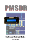
PMSDR
Software-Defined Radio for HF and VHF
v1.0 - Apr. 2011
“From Factory to Field Usage”
Copyright Notice
Without prior express written permission from RF<->SYSTEM ©, this manual may not
be transferred either in complete or excerpted form, using electronic or mechanical
methods, duplicated, or copied or otherwise transcribed by whatever method.
Information contained in the Manual may change without prior notification, and such
changes imply no obligations on RF<->SYSTEM ©.
.
Copyright 2011 RF-SYSTEM ©
http://www.rfsystem.it
http://www.iw3aut.altervista.org
Introduction
Contents
Introduction
Assembly Instructions
PMSDR Circuit Board
Optional Display
Optional Enclosure
Optional T/R Switch
Optional VHF/UHF Down-Converter
Driver and Software Installation
Specifics for the PC Software Program HDSDR
Choice of a Suitable Soundcard
Testing the Soundcard / Soundcard Tester
Installing the DLL
Techniques for Use with HDSDR (Pan-Adapter)
Ways of using the EXTIO_PMSDR.INI
FM Reception in 3rd Harmonic-Mode
Examples
DREAM
PowerSDR-IQ
Winrad Variants
Firmware Updates
Accessories
Lab Report
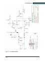
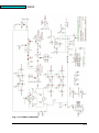
Circuit Diagrams
Trouble Shooting/Test Points
Appendix I
Introduction to the Fundamentals of SDR Technology
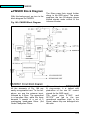
PMSDR Block Diagram
References, Links, Legends
Panadapter Mode: Quick Outline
Appendix II
PMSDR & WIN7
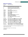
WinRad: Hot Keys
The CD
Liability Disclaimer
Freeware
Key Word List / Index
4
6
10
13
16
17
22
26
33
37
39
44
50
64
69
73
77
82
85
93
99
102
105
113
115
117
119
130
131
132
133
135
3
Introduction
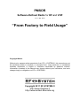
Introduction
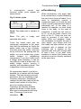
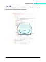
The PMSDR is an example of a
QSD-SDR Receiver (Quadrature Sample-Detector; Software-DefinedRadio). The concepts applied here
produce a clean output spectrum,
very low phase noise, and an almost
unbeatable cost/capability ratio. This
way, one may produce a small but
capable SDR receiver with a general
suitability
over
the
complete
shortwave domain. The control
connection to the PC, as well as the
DC power, takes place through a
USB connection. The I/Q outputs are
connected to the stereo line input of
the PC’s soundcard. Audio is
available via either headphones or
loudspeaker.
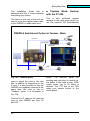
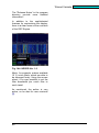
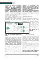
Fig. 1: PC-PMSDR Connections
This offers a simple and capable
solution for all conceivable options
for long and shortwave reception.
A novel use of oscillator overtones
makes even VHF reception possible,
with only a small loss of sensitivity.
Reception is also possible in the 2m
amateur band (144MHz), without an
additional converter.
If there is concern over restrictions
imposed by this method, an optional
down-converter is available.
4
■ Free Software
Ultimately, reception takes place on
the PC via free software.
The connecting link between the
hardware and the control software is
a so-called DLL (Dynamic Link
Library). This DLL contains program
code used by both the PMSDR and
the PC control software.
With this DLL, PMSDR possesses
wide ranging capabilities. Among
others, it will function as a
bidirectional, tunable Panadapter.
There are many additional options,
interconnection possibilities, and
CAT-Interfaces to other programs as
well, including several transceivers
that are already available, or being
continuously adapted and further
developed.
PMSDR works optimally and with
support of all the capabilities offered
by the DLL mentioned above, with
the outstanding software program
“Winrad.“ Winrad was first developed
for Windows by Alberto (I2PHD), but
unfortunately this software was not
further developed by its author.
Alberto graciously placed the source
code in the public domain. Capable
individuals
are
continuously
developing
these
programs.
Construction Notes
On the accompanying CD you will
find the most current Winrad version
in its original form [3] as well as its
extension as HDSDR [8] (previously
WinradHD), and WRplus [10].
There has been a further very
significant development in a program
called WinradF [9]. Unfortunately the
link to the home page of this author
is inactive, and at present no one
knows if this important beginning will
be followed further...
With a loss of a bit of operator
convenience, PMSDR can also
operate with PowerSDR-IQ, with
G8JCFSDR Software, as well as with
the SDR Shell for Linux.
All modes can be received with this
software.
Virtual
interfaces
(additional software, for example:
VAC, Com0Com, VSPE; on the CD)
make possible operation with other
software, for example that for digital
modes.
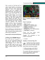
■ The Receiver
The receiver in the PMSDR is
designed to be a highly capable allband receiver for the frequency
range 0.1-55 MHz. Thanks to the
excellent properties of the mixer,
supported by automatically switched
preselection filters, the large signal
behavior
is
unusually
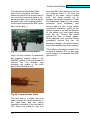
good.
Experiments with the large 40m fullsize loop from the QRP-Project [5]
have demonstrated that the PMSDR
shows that it can, even in the
evening hours, and without a
preselector, receive the weakest
amateur signals. Therefore, PMSDR
is an ideal tool for monitoring for the
amateur radio operator as well as for
the shortwave listener. Even friends
of the “magic band“ can listen in on
the activity of the 50 MHz band
without difficulty.
■ Requirements on the PC
The requirements on the capabilities
of the PC are not severe. Even
running the system on a netbook
causes no problems with PMSDR.
■Further Development
PMSDR
is
continuously
in
development. Please visit the
developer’s web site on a regular
basis [1]. You will probably find a
current DLL, or also new Firmware
which can be quickly installed in
PMSDR over the USB connection.
You
will
find
detailed
technical information in an
Appendix.
5
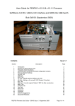
Construction Notes
Construction Notes
Switch (Switchboard) and DownConverter.
This kit is tailored to meet your
particular requirements. All parts that are
really difficult to handle (surface mount
devices) have been installed on the
circuit boards by professional circuit
board producers using automatic
positioning devices.
To complete the kit, only the installation
of the uncritical, larger components
(such as LEDs, headers, sockets,
crystals, and so forth) remains. This
requires no experience soldering SMD
components, greatly facilitating the
mounting process. One estimates the
necessary time for assembly of the main
circuit board and enclosure to be
approximately one hour!
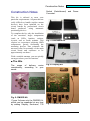
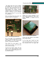
Fig. 3: Enclosure Kit
With a suitable antenna, you are quickly
on target to hear your first stations.
■ The Kits
The scope
considerably,
needs.
of delivery varies
according to your
Fig. 4: Display Kit
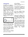
Fig. 2: PMSDR Kit
Figure 2 shows only the PMSDR Kit,
which can be expanded at any time
by adding Display, Enclosure, T/R
6
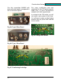
Fig. 5: Down-Converter Kit
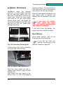
Construction Notes
■ Protect against Static
Electricity!
During soldering and when handling
the boards, one must be certain to
provide full protection against static
electricity.
Fig. 6: Switchboard T/R Kit
■ Tools needed:
You will find the following set of tools
to be adequate:
-Solder: ca. 0.5 to 0.7mm
-Desoldering braid: 2.5mm
-Soldering iron: ca. 30 to 50 watt, best
if temperature regulated and with a
narrow chisel tip.
-A small electronics sidecutter and
various screwdrivers will be useful.
-A particularly useful device is a “third
hand,” which greatly facilitates the
work. Circuit board holders of various
types are available (vide [6] or [7]).
Electrostatic discharge can easily
destroy the chips on the circuit
boards. Such damage can cause
later difficulty in troubleshooting and
in localizing problems. A grounding
strap or wrist band is not absolutely
necessary, but if you have one, use
it. Touching a grounded surface,
such as a nearby radiator or the
exterior of your soldering station is
sufficient. IF you should feel a static
discharge (a “shock”), regard this as
“Level Red” and look for the reason.
Are you perhaps standing on a
carpet? If so, use a different
workplace. If you are wearing felt or
fur slippers, immediately change to
other shoes (or work barefoot).
Components that are particularly
static-sensitive are marked in the
parts list and specifically pointed out
in the assembly instructions. Be sure
to leave these parts in their antistatic
packaging until you are actually
ready to use them. The packaging
consists either of an antistatic plastic
bag, or conductive plastic foam into
which the leads of the parts are
inserted.
■ Soldering
Fig. 7: Third Hand
If this is your first experience with
soldering on circuit boards, please
definitely
read
further.
The
experienced among you can skip this
section without further ado.
7
Construction Notes
All circuit boards are double sided,
and all holes are plated through. This
means that one does not have to
(and should not!) solder on the
component side of the boards. In a
few cases (changes in the enclosure
originating with the vendor), it may
become necessary to place a
component on the conductor side of
the board. Always work with a
preheated soldering iron. If you are
able to set the temperature of the
iron, use 350°C to 400°C. Use a
minimal soldering time! Beginners,
particularly, have a tendency to stay
on a solder point too long, detaching
a conductor trace and applying an
excess of solder. One should never
use any additional soldering aids
such as liquid flux, soldering paste.
Modern-day solder for electronics
use contains a core of flux that
already serves this purpose.
■ Lead-Free, If You Please!
At present, there are solders of
various compositions. The high toxic
lead content makes it necessary to
comply with the provisions of EHS!
During soldering, do not place your
nose directly in the smoke coming
from the operation! Commerciallyavailable so-called "environmentally
friendly" solder has not been proven
in practice. The cheapest and most
widely used alloy, called Sn64Pb36,
consists of 64% tin and 36% lead.
Compositions with 2% copper or
silver have a lower melting point,
which
makes
the
soldering
somewhat easier, and the joints are
noticeably shiny.
The latter has of course no particular
electrical significance, but pleases
8
many hobbyists. Whether you use
silver or copper based solder makes
no real difference except to your
wallet!
■ 30-50 Watt Soldering
Station
A soldering station that works with
low
voltage
and
potential
equalization is optimum. Please do
not use one of the old soldering iron
models, in which the tip is inserted
into the core and held in place by a
screw. In this old style iron, the tip is
often poorly held in the heating
element and has, on this account,
very poor heat transfer. If you need
to buy a new iron, please buy a
modern one. These irons have a
plated tip and are pre-tinned.
Keep the soldering iron tip clean as
you work. Use a damp sponge or a
damp cloth to clean the tip regularly.
An 0.8 to 1.0 mm tip is ideal for
normal circuit board traces. For
large-area surfaces, this kind of tip is
not really suitable, and a somewhat
broader tip (so-called chisel point) is
advantageous because of the
improved heat transfer. At least
these two tip types are useful. They
can be interchanged when it
becomes necessary to solder, e.g.,
some large flat surface. Only heat
the point being soldered just
sufficiently
to
give
a
good
connection.
A small circuit board holder makes
working on the board easier.
Construction Notes
In
cross-section,
correct
and
incorrect solder joints appear as
shown below:
Fig. 8: Solder joints
Good: The solder joint is concave in
shape.
Poor: The joint is
saturated with solder.
lumpy
and
Touch the board trace and the
component connection at the same
time with the soldering tip. Apply the
solder within one or two seconds.
First take away the solder, and then
the tip of the iron. Be sparing with the
solder; too much solder may cause
solder
bridges
to
neighboring
components. If you don’t notice such
a bridge while soldering, it can be
very difficult to find at a later time. If a
solder bridge occurs, remove it
carefully with desoldering braid. This
is described in the next section.
■ Desoldering
When desoldering, only apply heat
for a minimal time, to avoid detaching
the circuit trace from the board. If you
need to completely remove a
component again, cut it with the side
cutter in such a way that each lead is
individually left. In the case of a
resistor for example, cut both leads
close to the body. In the case of
transistors, 3 leads are left, and on
an IC, cut all the leads, close to the
body of the IC. There are now two
ways to proceed: If you have a
helper (Wife, son daughter, friend;
not necessarily an expert) the rest is
quite simple: your helper pulls the
free leads one after another on your
command with a tweezer as the
soldering iron is applied on the
opposite side with just enough heat
to melt it free;. If you don’t have
someone to assist, both heating and
extraction must be cleverly executed
at the same time.
All components should, in so far as
possible, be in contact with the board
surface. This has nothing to do with
aesthetics, but is a necessity in high
frequency technique. Accordingly,
resistors lie with their body flat on the
circuit board unless of course they
are to be installed vertically.
Capacitors are likewise installed
against the board. In other words,
there are no components with long
legs. (These are to be found
elsewhere ... )
9
Construction Notes
This works best with the aid of a
stable board holder, as mentioned
above. When the leads have been
removed, then the component
hole(s) can be cleaned with
desoldering braid. Use braid with a
width of 2.5 mm, and always work
with a clean, fresh piece. Cut and
discard used pieces of the braid
before using it anew. Put a small
surface of the braid on the solder
point, then put your soldering iron
lightly against the braid, until the
solder is sucked up into the copper.
The component can then be easily
removed, replaced, and soldered
cleanly in place. Use a circuit board
holder, as we have mentioned
several times already. This frees
both hands, and also makes the resoldering go much more simply!
Since soldering is a general part of
electronics assembly, we give here a
URL containing videos dealing with a
wide variety of situations:
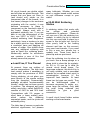
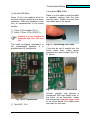
Fig. 9: Insertion Diagram, PMSDRBoard
Parts / Locations:
[
[
[
[
[
[
[
] Red: Crystal
] Orange: 3x USB/BNC Jacks
] Green: 2x 2-rowed headers
] Yellow: LED Block
] Violet: HF-Transformer
] Bright Blue: 3x 1-rowed headers
] Dark Blue: 2x Buttons
Check
the
box
when
component type is installed.
each
www.solder.net/technical/tips.asp
■ Filling the PMSDR Board
Crystal: The orientation
crystal is immaterial.
of
the
[ ] Crystal
Let's start with the installation of a
few of the remaining additional
components. Refer to the colorcoded diagram, Fig. 9. Take care
that the BNC jacks lie flat on the
board. If this is done, their leading
edge is exactly parallel to the PCB
edge.
Headers: (vide also Page 14!)
Headers are always mounted
with the short ends inserted
into the circuit board. Make sure that
they sit flat on the board surface.
[ ] 2-Rowed Header (2x10 PIN’s)
[ ] 2-Rowed Header (2x 8 PIN’s)
The double LED block must also sit
squarely and parallel, aligned with
the front edge of the board.
10
Construction Notes
It is marked: MCL T4-6.
[ ] Double LED Block
Some of the row headers must be
cut from a longer header with a sharp
sidecutter. Place the headers so that
they sit perpendicular to the board
surface.
Place it on the pads so that the label
is readable viewing from the side
with the jacks. Solder as usual from
the solder side of the board.
[ ] 1 Row, 8 Pin Header (SV1)
[ ] 2 ditto. 1 Row, 2 Pin (JP2/JP3)
Nothing is to be installed at
positions SV4, SV5, SV6, and
JP1.
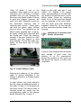
The small six-legged component in
the components package is a
prefabricated HF transformer.
Fig. 11: Positioning the Leads
If the pins do not fit straight into the
holes, bend them using gentle
pressure on a hard surface, as in Fig.
11 above..
Fig. 12: Alternative Conformation
Fig. 10 HF Transformer
[ ] Trafo MCL T4-6
Another supplier may provide a
component with legs clearly bent to
the sides. As an exception, solder
this component from the upper side
of the circuit board. The solder pads
are ready for this case.
11
Construction Notes
Jacks and Buttons:
Again, note that these sit level on the
board, and are aligned parallel to the
front board edge. On the ground pins
of the BNC plugs, use a suitably-hot
iron with a broad tip to avoid damage
to the board by overheating as a
result of heating too long. Even if the
buttons have a square shape, the
solder tails are not arranged in a
square but rectangular form. Don’t
use force on the solder eyelets;
insure that the solder tails sit exactly
over the solder eyelets. Press the
buttons carefully against the board.
The leads snap into place when they
are properly positioned.
[
[
[
[
[
] Stereo Jack for 3.5 mm plug.
] USB Jack
] 2x pushbuttons
] BNC Jack
] Antenna
Do not install if installing
the Switchboard option!
12
Construction Notes
■ Option: Display
If you didn’t order the display option,
skip to the section on installation of
the PMSDR in the enclosure…
There are displays on the
market that produce very
significant interference, and which
therefore have a severe influence on
the sensitivity of reception with the
PMSDR. The display we deliver was
chosen for its minimal interference,
and its power supply is also
decoupled.
Insert Spacers Here
Fig. 14: Display Assembly
At this point, prepare the ribbon
cable for connection to the display.
Fig. 13: Display Kit
The display unit, with adhesive and
frame, is delivered ready to use.
Examine Figs. 14 and 15 for
placement of screws and plastic
spacer.
13
Construction Notes
Pin-1
Pin-1
Potentiometer:
LCD-Contrast
Fig. 15: Display in place and
connected
Split the cable end opposite from the
connector as follows. Begin with wire
number 1 (with the red tracer). If your
cable has no red tracer, see Fig. 15.
missing. If possible, use your
fingernail rather than a tool. Divide
the ribbon cable between the 6th and
7th wire for 3 to 5 cm. Count further
to the 10th wire and divide the cable
again between wires 10 and 11.
Cut away about 2 cm of the free
section (wires 7-10). Now, again
using your fingernail, separate the
individual wires 1 through 6 and 11
through 16 so that the ends are each
ca. 2 cm long.
1-6
7-10
11-16
Fig. 16: Prepared Ribbon Cable
This shows how to identify wire 1 via
the connector if the color tracer is
14
Construction Notes
Strip off about 3 mm of the
insulation. Here again do not use a
sidecutter, as in so doing, it is highly
probable that you will damage the
thin wires and make breaks in them.
A good wire stripper, however, will
work very well. Especially good are
the automatic versions, with a
relatively wide “mouth.“ These types
can strip the ribbon cable, several
wires at once. The insulation on the
ribbon cable supplied can, however,
be easily nicked and removed with
the thumb nail. Check the resulting
strands. If they are fanned out, then
carefully use two fingers to twist
them together. Tin the wire ends very
lightly, so that there are no loose
strands.
Begin on the right with wire 1 and
solder 1-6. Eyelets 7-10 remain
open, corresponding to the fact that
you earlier cut back the wires on the
ribbon cable. Finish by soldering
wires 11-16. At this point the display
can be fastened to the front panel.
Use the 2mm nuts and bushings
supplied. Follow Fig. 14; the nuts are
on the innermost position inside the
housing.
Addendum for headers and
header connectors.
If your kit was supplied with mounted
pins instead of bare ones, the
printing 16 (or 20, respectively)
shows the position of the notch on
the board. Be careful to follow this
orientation.
Fig. 17: Solder Ribbon Cable
Subsequent soldering of the ribbon
cable is greatly simplified if the
display is placed in a suitable holder
or clamps.
In what follows, pay close attention
that the wires are soldered exactly in
the order 1-6 and 11-16. Nowhere do
two wires cross! The ribbon cable is
inserted strand by strand into the
corresponding pads of the display
board. Examine Fig. 15 and 17.
15
Construction Notes
■ Option: Enclosure
Installation
using
the
optional
enclosure is quite simple. Remove
the nut and lock washer from the
BNC jack, as well as the nut from the
stereo jack. Insert the back panel
right side up on the board edge
bearing these jacks, and install the
nut and lock washer on the BNC jack
and the nut onto the stereo jack,
leaving them loose.
enclosure screws. The screws will be
a bit hard to turn, as on first insertion
they have to cut their own threads.
When the back panel is attached, the
front panel (with or without the
display) can be screwed to the front
side.
If you have the display,
don’t attach the cover,
since the contrast potentiometer
may need to be adjusted.
If you don’t have the display, the
upper cover can now be mounted.
Best Wishes
We’re about finished, and not far
from receiving the first signals.
Fig. 18: Enclosure (Housing) Kit
Tighten these nuts before installing
the upper part of the housing...
Fig. 19: Insert Circuit Board Here
Slide the circuit board into the Ushaped lower section, using the first
(lowest) slot.
Now attach the rear panel at the
bottom with 2 of the 8 self-tapping
16
If you did not order any
options, skip directly to the
Start-up Chapter on page 25.
Construction Notes
■ Option: T/R Switch
(Switchboard)
Fig. 23: Switch Circuit Board
This board is, like the PMSDR board,
delivered with SMD in place.
Fig. 20: T/R Switch Option
The switch is available in two
variants, which differ only in the
cutouts of the rear panel. If you
ordered your kit including the switch,
you received rear panel Type 2.
Fig. 24: Switch Layout
Populate the board with the 7
components as follows:
Placement of Components:
Fig. 21: Type 2 Rear Panel; In this
case, do not install the antenna
jack on the PMSDR circuit board!
In the other case, i.e. when
retrofitting, you receive a rear panel
of Type 1.
[
[
[
[
[
[
[
] Rd: Relay
] Orange: 2x BNC Jacks
] Green: 2-Rowed Header
] Yellow: LED Block
] Light Blue: MMCX/SMA-Jack
] Dark Blue: LED Block
] Coax Cable with MMCX Plug
Install the individual components
according to their corresponding
colors.
Fig. 22 Type 1 Rear Panel
17
Construction Notes
You should first attach both BNC
jacks to the rear panel, and then
solder the result to the circuit board If
you try to first mount the jacks to the
board and then mount the rear panel,
the panel will not be exactly parallel
to the board (because the BNC jacks
have a little “play.“).
Fig. 25: Finished Circuit Board
Now it is only a matter of connecting
the supplied coaxial cable to the
PMSDR, putting on the pin header to
connect the two boards, and
screwing the board to the back
panel. But first things first:
Fig. 26: Prepared Coax Cable
The task now is to solder the coax
cable so that the shield connects to
the right lead, and the center
conductor connects to the left lead of
JP2 Orient the cable so that you
18
have the BNC jack directly in front of
you. Remove about 1 cm from the
sheath of the coax, using a sharp
knife, but being careful not to
damage the shield beneath it. Dress
the shield back away from the center
conductor (and insulation) and
remove about 5 mm of the center
conductor’s insulation. Lightly tin the
center conductor, as well as that part
of the shield you bent back away
from the tip. Tinning the shield
should be done in small stages.
Work stepwise, until you have tinned
completely around the rim. By
working in stages, you avoid melting
the center insulation by over-heating.
The cable is now ready to install. The
location is labeled JP2 on the main
circuit board. It is between the BNC
jack and IC1.
Construction Notes
Fig. 29: Interconnected Units
Fig. 27: Detail around JP2
Be sure to check carefully for a shortcircuit between the pins of JP2.
The two units will
connected as follows.
.
finally
be
■ Interconnection of the Units
Now screw the switchboard down to
the back panel. This secures the
small board via the 3 screws on the
jack.
Fig. 28: Connection to JP2
19
Construction Notes
Plug one side of the ribbon cable on
the board, as shown here.
Fig. 32: T/R Switch Installed
Fig. 30: Ribbon Cable connected
Put the small coax MMCX/SMA plug
carefully in its socket.
The PMSDR with the T/R switch
installed corresponds to one or the
other of these figures:
Fig. 33: Rear, Type 2; Completed
Fig. 31: Detail, MMCX plug
Screw the rear panel to the
enclosure, and finally connect the
other end of the ribbon cable to the
row of pins SV3 on the PMSDR
board.
The cable runs directly linearly from
the upper board to the lower board.
Finally, put the enclosure cover on,
and you’re finished.
20
Fig. 34: Rear, Type 1; Completed
Construction Notes
■ Alternative
Modification
Fig. 35:
Diagram
Detail
T/R-Switch
To install this, you only need to
remove the upper part of the
housing. The board is then already in
the correct orientation. The two
eyelets may easily be soldered from
the side turned toward you.
from
Circuit
Fig. 36: Additional Bridge
There
is
a
small
additional
modification that we want to share
with you. It allows simultaneous
reception via RX/TX and PMSDR.
This allows good comparisons to be
made between methods. You lose
only about 3 dB in sensitivity with the
two receiver inputs. Fig. 36 shows
the added connection. Use a short
piece of insulated wire as a bridge on
the underside of the board between
the two eyelets shown.
Important Notice: This modification
carries with it a risk of damage for
the switch board: If, for whatever
reason the RF vox fails or does not
respond, the full RF power of the
transmitter will go into the receiver
channel and in all probability damage
it. We therefore recommend that the
switchboard, when modified in this
way, not be used with the internal RF
vox, but that it be controlled by the
PTT output of the transceiver.
21
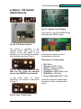
Construction Notes
■ Option: VHF/UHF
Down-Converter
Fig. 39: Type 2 Rear Panel
Fig. 37: Kit
The T/R switch function is built into
the down-converter. That is, there is
only an either/or installation option in
the existing PMSDR housing; either
the switch function or the downconverter with built-in switching
function.
Both the construction and the
installation in the PMSDR enclosure
run very similarly to the installation
already described for the switch.
Which of the two rear panels is
appropriate
depends
on
your
situation. If you are upgrading a
currently existing PMSDR, it is this:
Fig. 40: Component Placement
We have adapted the kit to the state
of the art, and now provide a fully
tested and calibrated board. (Fig. 37
still shows the old version). There are
three components to be installed:
[ ] BNC Jack
[ ] Double LED Block
[ ] 3,5mm plug jack
Figs. 40 and 41 show clearly the
positions of the parts to be used.
Fig. 38: Type 1 Rear Panel
If you are building from scratch, it is
this rear panel:
22
Construction Notes
The filters that are on the module
are already set up. (They are Filter
F2, C21, C28, und C29 for the 2m
Band, as well as Filter F1 for the
70cm Band.) For experts: Jumper
JP4/JP5 allows the connection of a
network analyzer for the extended
filter range for filter F2, (or for filter
F1 at JP2/JP3.)
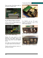
After mounting these few parts, the
board is ready for installation.
Fig. 42: Units Interconnected
Please pay careful attention to the
short coax connection to JP2 on the
board PMSDR. It should not be
twisted.
Fig. 43: Circuit board installed
Fig. 41: The fully populated board
As in the case of the switchboard
(above), strip the short piece of coax
and connect it to JP2 on the main
board. The process is identical.
Screw the rear panel to the bottom
part of the housing.
As the final step, install the front
plate and display panel, and close up
the enclosure with the upper half.
Now attach the rear panel in the
same way as before, and screw the
unit onto the housing.
Connect the ribbon cable and the
coax to the down-converter board
and to the corresponding points on
the PMSDR board.
23
Construction Notes
The fully assembled PMSDR with
down-converter again corresponds to
one of these two figures.
The same modification that was
mentioned for the T/R switch may be
made here, to allow simultaneous
reception with both apparatuses.
In contrast to the T/R switch, you will
not need to use a piece of wire here.
It is sufficient to make a solder bridge
between the two points with a bit of
excess solder.
Fig. 44: Type 2 Rear Panel
Fig. 46: Bridge with solder
Fig. 45: Type 1 Rear Panel
Fig. 47: Positioning the bridge
24
PMSDRP
PMSDR
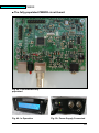
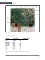
■ The fully-populated PMSDR circuit board
Fig. 48: Circuit Board fully
populated
Fig. 49: In Operation
Fig. 50: Power Supply Connected
25
Sound Card Set-Up
■ Setting up the PMSDR
■ Overview
1. Connect PMSDR to the computer
via USB cable and audio cable.
2. Install USB driver
3. Install HDSDR software.
4. Copy DLLs contained in the
HDSDR directory.
5. Set up and ready the PC sound
card.
6. Make necessary settings in
HDSDR.
7. Connect antenna and
8. Start HDSDR.
■In Detail:
■ 1.) USB and Audio Cable
Fig. 51:
Installed
USB
Driver
Properly
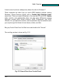
If the highlighted line shows the
same or similar, everything is OK. In
this case, proceed to Step 3. If the
driver is not found automatically, the
Device Manager shows:
Connect your USB and audio cable
to your computer.
■ 2.) Install USB Driver
The PMSDR is both powered and
controlled through the USB Port.
The necessary drivers should
already be present (automatically
installed) in Windows XP, Windows
Vista and Windows 7. In case they
are not, install them by hand as
described below.
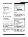
Windows automatically signals that it
has found new hardware when a
USB cable is connected. If the
system recognizes the necessary
driver, then a subsequent call to the
Device Manager shows a screen
similar to:
26
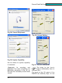
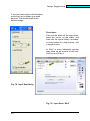
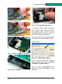
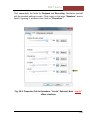
Fig. 52: USB Driver not recognized
In this case, you must intervene by
hand. Right-click on the line in
Device Manager with the yellow
alarm labeled „PMSDR USB Board“,
in order to open the context menu.
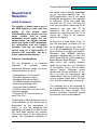
Sound Card Set-Up
We proceed with a question &
answer game. Answer the question
about “automatic updating“ with “No,
not this time,“ and click on „Proceed“
In the next Dialog click on the
buttons
“Search
the
following
sources“ and “Search.“ Now select
the path to your CD drive (containing
the CD we provided). On the CD, find
the
folder
PMSDR_MCHPUSB
driver, click on it, and answer OK.
This will locate the driver and install
it. Device Manager should now show
“Microchip Custom USB Device“ as it
appears in Fig. 51.
As soon as the driver is installed, the
green LED on the rear panel of the
PMSDR should come on, and if you
have the display installed, it will light
up in a blue color.
If you have the display option
installed, the trim-pot R7 next to the
display cable plug should be used to
adjust the contrast according to your
taste. The upper half of the enclosure
can now be replaced and attached
with the self-tapping screws provided
■ 3.) Installing Software
You should now install appropriate
software for your PMSDR. The
Winrad series from Alberto (I2PHD)
is ideal, capable, and simple to
operate.
Other programs, such as the oftenrecommended “PowerSDR-IQ“ are
harder to configure and use. These
non-Winrad based programs do not
support the above-mentioned DLLs
very well, which consequently
significantly limits their utility.
If you wish to run Winrad with
HDSDR on a netbook, you are better
off with this version, which can
compensate for the limited vertical
resolution of the netbook. The
program can be called up with a tag
(-wv), which fully utilizes the
available resolution in each case. Of
this, more later.
Pick out the installation file for
HDSDR from the PC-Software folder
on the CD, and start the installation
program. The best choice for the
requested parameters is to leave
them with their default values.
HDSDR will then be put in the folder
“c:/Programme/HDSDR“ (WinXP)
(“Program Files“ for Win7).
■ 4.) Copy DLLs
The DLL files mentioned above must
also be put into this folder, so that
PMSDR can talk to HDSDR. Using
Windows Explorer, call up the folder
on the CD that contains the DLL files
The following example was created
with the use of the very advanced
program
suite
HDSDR,
from
DG0JBJ. Use Windows Explorer to
access the DLL directory. Copy the 3
DLLs contained there, and also the
package HDSDR, from DG0JBJ.
27
Sound Card Set-Up
and copy the 3 DLL files into the
program folder of HDSDR. They are
“cc3260.dll,“
“ExtIO_PMSDR.dll,“
“mpusbapi.dll“.
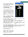
Update the DLLs
We have already mentioned earlier
that these DLL are continuously
under development. Therefore it is
appropriate to look for new versions
on the web site of the developer from
time to time. With new versions, you
simply proceed as usual. The DLL
are presented in “zip“ format. That is,
these files are compressed to save
space, and must be unpacked to
recover the original form. Double
clicking opens the archive. The 3
files inside should be copied to the
HDSDR folder. Answer with “yes“ to
overwrite the prior versions.
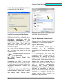
■ 5.) Prepare the Sound Card (XP)
PMSDR puts out two 90-degree
phase shifted audio signals. These
are the so-called I/Q signals, which
are worked up to an audible signal in
the sound card. These signals must
be processed in parallel.
Your sound card must have a
stereo input!
Unfortunately this is not the case with
some sound cards. Check your
available sound card for stereo
capability. We proceed assuming
that your computer is outfitted with a
stereo input. Connect the computer
to the PMSDR with a stereo cable.
28
Audio Connection
In most usual cases you will need a
cable with a 3.5 mm stereo plug on
both ends. To avoid distracting
influences, it is useful also to connect
headphones to the headphone
output jack.
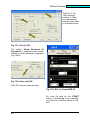
Fig. 53: The Samsung NC10
(Microphone Input = Pink; Line
Output = green)
Figs. 53-55 show typical sound card
inputs for various computers. (NC10
vide P. 37)
Sound Card Set-Up
Fig. 54: Standard Laptop Line-In
Fig. 55: Standard PC Line-In (Blue)
For making the following settings on
the PC only minimal computer skills
are needed.
Make the settings as you see them in
the following pictures.
Fig. 57: Audio Properties
The following examples are taken
from Windows XP, with a Realtek
AC97 Audio sound card, which is
standard in most notebooks.
A
short
series
of
pictures
subsequently shows the calls for
Windows 7 (vide Appendix).
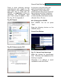
Bring up Control Panel from the Start
menu and double click “Sounds.“
Make the settings as you see them in
the following pictures.
Fig. 56: Sounds and Audio
Click sequentially the fields for
Sound Reproduction and Sound
Recording. Choose AC97 as the
default.
In the Advanced box, set the speaker
output to headphone output.
29
Sound Card Set-Up
Fig. 58: Choose Earphones
Fig. 60: Volume Setting
Fig. 59: System Capability
Set the sliders for system capability
to maximum.
(Separately for recording
and
playback) You want everything not
absolutely necessary to be off, so
that only the necessary control fields
remain.
30
Fig. 61: Line-In to Minimum
The slider for the Line-In
input is deliberately close to
the lower limit,
The levels at the I/Q output of the
PMSDR are relatively high, so use
Sound Card Set-Up
the least input amplification possible.
Be sure that all the balance sliders
are in the middle!
The following Recording settings
active: Only Line-In!
The adjustments now showing up
have been reduced to a minimum.
The only input appearing on your
notebook or PC MUST be a stereo
input.
Your PC manual should answer the
question in this case.
Fig. 63: Playback Choices
Fig. 62: Recording Choices
At this point, using “options“ and
“properties,“ you have deactivated
everything not in use.
The following Playback
settings
active:
Only
Loudness and Wave!
Fig. 64: Additional functions
If this is not the case, use the
microphone input, not the line in jack,
but please note that
:
Mic-Boost must
switched on!
not
be
31
Sound Card Set-Up
In the advanced installation, there is
a check box for “Mic Boost.“
Fig. 65: Do not check Mic-Boost.
Nothing should be activated here,
otherwise everything will be
hopelessly overloaded! If your
microphone input is also not a stereo
input, you must first get an
appropriate USB sound card*, then
proceed as usual.
As a rule, all line inputs are stereo,
so it is likely that there is no real
problem here.
* Suitable models are listed
in an Appendix.
5a.) Win7 Sound
Appendix II
Cards.
See
Procedures for WIN 7 run in an
analogous way to those given for XP.
A short series of pictures offers the
necessary assistance, should you
require it.
A left mouse click on the WIN 7 Start
symbol opens a dialog box, in which
you simply enter “sound card.“
32
Normally this opens a selection box
with fairly obvious choices:
Fig. 66: Keywords “Sound Card“
Simply click on “Change Sound Card
Installation,“ if this choice appears.
Fig. 67: Recording
The new window shows you a
summary
of
all
installation
possibilities for Recording and PlayBack.
It is unfortunately the case that
computers offer a large range of
possibilities for setting up sound
cards. Some computers come with
built-in sound. Some users choose to
replace the built-in sound with a
sound card, which will usually come
with
a
software
management
package
that
offers
differentappearing control applets. A general
principle to remember is that the
basic on-off control of built-in sound
hardware is available through the
system setup utility (usually by
pressing F2 at boot time).
Sound Card Set-Up
There is some uniformity amongs
manufacturers with regard to the
color-coding of the analog line-level
input jack that is used with the
PMSDR…it is light blue. If there is a
rear-panel L/R microphone input
jack, it will usually be pink in color.
See Fig. 55-2 in Appendix II.
At this point, and particularly with
add-in sound cards, look under
“Properties“ to see if there are
enhancements that can be turned off.
Among these would be “Equalizers,“
“Power Saving,“ as well as all sorts
of other functions that distort sounds
(Reverb, Echo, 3D, etc.)
Fig. 68: Repeat
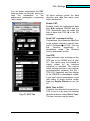
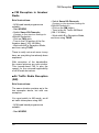
■ 6.) Settings for HDSDR
Boot HDSDR, but do not press
“Start.“
Enter the following choices on the
HDSDR screen:
Sound-Card Button:
Fig. 69: Enhancements Off!
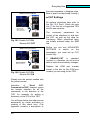
Fig. 70: Sound-Card Selections
Make the choices for Input/Output
here.. Definitely use headphones for
listening to signals.
Otherwise it is difficult to avoid
unpleasant cross-talk effects.
33
Sound Card Choice
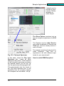
Soundcard Sampling Rate Button:
Fig. 71: Choosing the sampling
frequency
Fix the sampling rate (48 KHz, 96
KHz, 192 KHz).
The AC97 only allows a sampling
rate of 48 kHz. (see PC manual for
information.). The rate showing on
the right is set automatically by the
program.
Sound-Card Options Button:
Fig. 73: DLL GUI
Choosing “PMSDR“ causes the GUI
to appear at once: The I/O window of
the DLL. (GUI stands, by the way, for
Graphical User Interface, namely the
operator service window.)
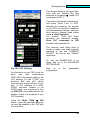
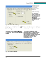
Fig. 72: PMSDR Data Input
Fig.
74:
Choices
Choose Select Input
Choose PMSDR
Be sure that the MME 16 Bit drivers
are activated, as in the picture.
Choose the Channel Mode, and be
sure that the I/Q Mode is activated.
34
Sound-Card
Driver
Image Suppression
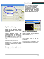
Fig. 76: Inverting I/Q Input
Fig. 75: I/Q-Output
■ Adapting Screen Size:
Previously mentioned options for
matching the screen resolution are
found
under
OptionsStartup
Options (called “Window View“;
abbreviated wv).
If, during SSB reception in lower or
upper sideband, the signals are not
decoded, (speech sounds strangely
distorted), use Swap I/Q Channels
to invert the signal.
For a netbook with its decreased
vertical resolution, these settings are
probably not available. In this case,
start the program with the tag “-wv“.
Go to the desktop of your computer,
and call up the connection to the
program path with a right mouse click
on the HDSDR icon, under
Properties. This should now read:
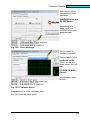
Fig. 77: 80m Band Reception
"C:\Program\HDSDR\HDSDR.exe –
wv“ (For WIN 7: "C:\Program
Files\HDSDR\ HDSDR.exe –wv“)
There is one further setting for
reception:
■ 7.) and 8.) Connect Antenna
and click START Button
Clicking START should now show a
picture similar to that in Fig. 77!
Listen using earphones.
35
Image Suppression
If you don’t see noise in the baseline,
move the Line-In slider up a small
amount. This should lead to the
desired image.
Procedure:
First pull the slider all the way down,
leave the cursor on the slider, and
then use the arrow button „increase“
to move further up, step by step, until
a signal is seen.
In Win7 a more elaborate window
may show up as a result of this call.
Don’t be put off by it.
Fig. 78: Input Sensitivity
Fig. 79: Input Sens. Win7
36
Sound Card Choice
Sound Card
Selection
Initial Comment:
The quality of what comes out of
the SDR stands or falls with the
quality of the sound card!
Unfortunately one cannot use the
same criteria that a music
enthusiast would apply. For the
same reason, the various reviews
which one finds in HIFI magazines
are misleading and not usable;
consider that we are using the
sound card as a high-quality 2channel A/D converter, not as a
music reproduction device!
Practical considerations:
For our purposes it is therefore
important
to
consider
some
completely different things of a more
technical nature, such as:
- Outstanding A / D converter?
- Excellent dynamic range?
- Equipped with stereo input?
- Full duplex signal processing?
- Built-in anti-aliasing filter?
- Low-pass filter available?
- Uniform noise floor over the entire
frequency range?
- Internal DC-DC run-out close to
zero? Etc. Etc....
our sound card is directly dependent
on the so-called sample rate. For
SDR applications, this is the same
bandwidth as shown on the waterfall
or spectrum. There are cards that
can yield 48, 96, even 192 kHz. Be
sure you purchase a card with 24 bit
resolution, not one with 16 bit
resolution! The 24 bit choice will
already do everything that the 16 bit
choice will. There is no question
which is the better!
At this point, a word about 16 vs. 24
bits. On one hand, one talks of 16 or
24 bit drivers, and on the other, of
16- or 24 bit resolution. These really
have nothing to do with one another.
Window’s own WMME interface
generally operates with 16 bits, the
ASIO driver with 24. (ASIO stands for
Audio-Stream-Input-Output).
The
latter driver will usually produce
better timing with the "run" behavior
of the signals. This is the so-called
latency period. Windows native
drivers are usually sufficient for us.
But it is, from our experience, not
reasonable to first buy a 48 kHz card,
only to replace it later with a 192 kHz
one. The price difference is minimal!
The following list is not intended to
be comprehensive, but merely offers
something for every budget. The
internet provides technical details
and current prices in abundance!
Unfortunately, these details are not in
most manuals, so that either one is
dependent on the experience of
others, or one has adequate test
capabilities at hand to be able to see
the card itself behind the scenes!
This is the basis for the table given
below. The bandwidth capability of
37
PMSDRP
Images
One final comment: First try what
you have available before you
spend a lot of money for something
new! The built-in sound cards in
computers or notebooks are usually
adequate, as long as they provide
stereo inputs.
Always use the LINE-input! (Only
this input is usually set up as the
stereo input needed by PMSDR.)
The tried and true SAMSUNG NC10
is an exception. This small computer
has no line-in input on its high quality
built-in sound card, only usually a
microphone input and a headphone
output.
Nevertheless,
the
microphone input is stereo, and can
therefore be used for our purposes!
One limitation: this card can only
produce a 48 kHz resolution.
The boxed text to the right may be of
some help in finding a sound card.
The prices shown are only
approximate, and will vary from
vendor to vendor, sometimes over a
large range. Some of the cards
labeled “discontinued” show up used
in places like eBay, or even new in
Amazon. Shop around!
The following cards are well
suited to our applications, not
only for the PMSDR, but also for
every SDR.
ESI JULI@PCI, PCI, to 192 KHz,
(discontinued, hard to find)
ESI MAYA44e, PCIe, to 96 kHz,
(discontinued, hard to find)
Infrasonic Quartet, PCI, to 192
KHz, ca. US$ 100 (discontinued,
available)
Creative EMU-1820, PCI with
external connection box, to 192 kHz,
ca. US $ 200-300
Creative EMU-1212, PCIe with
external connection board, to 192
kHz,, ca. US$ 160-260
Creative EMU-1616, to 192 kHz,
various forms: PCI, PCIe, with ext.
Interface, ca. US$ 350 to 450
Creative EMU-0404 USB to 192
kHz, ca. US$ 175
Creative EMU-0202 USB to 192
kHz, ca. US$ 90
Creative EMU-0204 USB to 192
kHz, ca. US$ 130
M-Audio Audiophile to 192 kHz
PCI ca. US$ 200
The bold-face suggestions are
especially suited and
recommended for 192 kHz use.
Fig. 80:
Cards.
38
Selection
of
Proven
Image Suppression
Sound Card Test
Extremely helpful for this is a test
device with which you can see at a
glance what is going on, and from
which you can judge suitability or
non-suitability.
The circuit is relatively simple. A
time, NE555, is used as a tone
generator. Two RC elements, as
phase shifters, emulate the I / Q
signals. The phase difference of 90
degrees is only true for the
fundamental. The output frequency
of this device is somewhat
dependent on power supply voltage.
For 6V one gets ca. 15 KHz; for 9V
ca. 17 KHz.
Such a test device can be built up
quickly and without problems, using
a small project board.
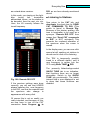
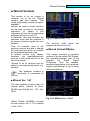
Fig. 81: Soundcard-Tester
This small test circuit is driven from a
battery pack, and costs only a few
Euros. It generates test signals
which are fed into the sound card to
be tested. The screen image from
HDSDR then gives information on
the suitability or non-suitability. If
nothing seems to go, and nobody
knows why, this little device can
quickly provide insight. You can get
the completed tester from [11].
Fig. 82: Phase shifter built from a
NE555
39
PMSDRP
Images
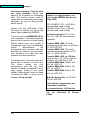
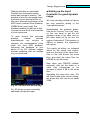
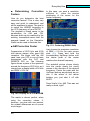
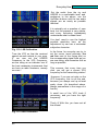
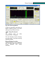
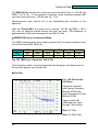
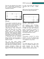
The original signal is clearly seen on
the right at ca. 17 kHz, while the
image
appears,
significantly
suppressed, at left. The difference in
these values shows an excellent
innate image suppression of about
70 dB.
Fig. 83: Carrier and Image Signal
When a connection is made to
the soundcard input, the result
should look something like Fig.
83.
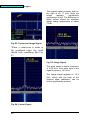
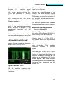
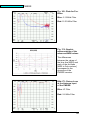
Fig. 85: Image Signal
The scale shows a center frequency
of 3760 kHz. Also seen here is the
signal frequency, 16.5 kHz.
The image signal appears at -16.5
KHz, which with the help of the
channel skew calibration, can be
further significantly reduced.
Fig. 84: Carrier Signal
40
Image Suppression
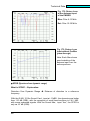
■ Image Frequency Suppression
Use the Options button to open the
calibration window.
Fig. 86: Channel Skew Calib.
Setting the slides requires a lot of
care! It does not matter at first
whether you start with the amplitude
or phase. Start with the Coarse
slider, and move it VERY slowly,
while watching the image signal. The
point is to minimize the image signal
by mutual adjustment of the two
pairs of controls.
When the Coarse slider produces no
further result, then turn to the Fine
slider. These settings are somewhat
interdependent. Set to work carefully
with both controls until you have
succeeded in minimizing the image
signal. With careful handling, you
can nearly null out the image, as
shown in Fig. 87. At this point the
suppression of the image frequency
produces a suppression of a whole
85 dB! We do have to point out that
(unfortunately) this is an “average“
setting. That is, the result you obtain
actually pertains precisely only for
this single frequency.
Reception frequencies that lie
markedly right or left of this one,
show less image suppression.
Fig. 87: Resulting Suppression
An automatic, constantly re-adjusting
determination of the correction value
would be extremely useful. (Keyword
phrase: WBIR; Wide-Band-ImageRejection). In some software suites
(PowerSDR, Rocky [14]) something
like this is already implemented, but
unfortunately not yet in HDSDR.
41
Soundcard Control
Soundcard Control
It should look like:
Requirements:
The PMSDR is fully connected,
but NOT turned on (USB plug
removed).
For this test, it does not matter
whether
an
antenna
is
connected or not.
In HDSDR, all settings have been
made as indicated above.
HDSDR has been started using
START
Fig. 89: PMSDR Chosen
- A signal at the LO frequency
produced a DC signal by mixing
effects,.
- Many sound cards are AC coupled.
If this is the case, you will see a
black stripe and no line!
- If the sound card is DC coupled,
then a few mV of DC offset will
produce a strong signal at the center
frequency. A little DC offset will
produce a gigantic center peak.
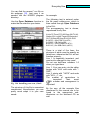
Fig. 88: Soundcard selected.
For Select Input, you currently have
only Sound Card to select. PMSDR
is grayed out, since it is not
connected. Choose Sound Card.
The result is a more or less narrow
line in the center of the frequency
scale.
If one looks further into this matter,
one finds the following causes:
42
But that is only the beginning! There
are many totally-different signalpaths in a sound card, and at least
as many (or mutually incompatible)
ways to connect them with each
other.
These
pathways
are
directly
influenced by the various links in the
relevant software.
Image Suppression
What sounds like an unsolvable
Gordian knot fortunately usually
works well enough in practice. The
problem is that one can spend many
frustrating hours working at this. In
this case, alternative activation of the
ASIO driver (instead of the Windows
WMME driver) may help! The
broadest meaning of that line is that
it shows the sum of all non-linearities
of your sound card.
To work around this user-side
problem,
market
oriented
manufacturers
are
striving
to
integrate the corresponding audio
chips into their SDR products.
Assuming the hardware of your
device to be OK, different images
illustrate problems with the settings
of your sound card!
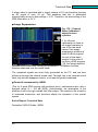
■ Setting up the Input
Controller for good dynamic
range.
We have already pointed out above
the very sensitive setting of the
“input potentiometer.“
Nevertheless, the question arises,
how far do I have to "turn it up" here,
on the one hand to get the full
dynamic range of my card, and on
the other hand not to go into the
region of saturation? This question is
difficult to answer, but experience
will help us.
Do exactly as before, as indicated
above for the sound card control,
and note the level of the noise floor.
Use a ruler laid across the noise
floor, and read the noise floor for
HDSDR on the left scale.
Now close your PMSDR (without
antenna!), and set the slider to a
value that corresponds to an
increase of about 6 dB in the noise
floor.
Assuming the noise floor was -103
dB, then at about the correct setting,
the noise floor will now be at about
97dB.
Fig. 90: It should not be this way!
Fig. 90 shows an open and totally
saturated microphone input.
43
Everyday Use
The DLL and its
Settings
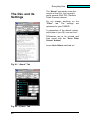
The “About“ tab merely notes the
version of the DLL, the copyright,
and a general GNU GPL (General
Public License) release.
Do not change anything on the
“Filter“ tab. The settings are
optimized for your PMSDR.
A comparison of the default values
with those of your DLL can not hurt!
Differences are to be revised and
then saved with the “Save Filter
Values“ button!
Leave Auto Select switched on!
Fig. 91: “About“ Tab
Fig. 92: “Filters“ Tab
44
Everyday Use
for routine use of the system are
given.
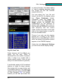
Fig. 94: Quick Tune Tab
The Debug window is used primarily
by developers to detect errors. Don’t
change anything here!
For example, here you can set the
possible speed-dial settings to your
own taste. More on that later, in the
section dealing with the initialization
file (*. INI) of the DLL. The ± Fast
Tune button places the preset
Tuning Steps values on the
frequency bar. The button “Write
It is of interest to open the Quick
Tune window; various possibilities
TUNE RIG“ transfers the
selected frequencies to the TRX.
Fig. 93: “Debug“ tab
45
DLL Settings
in various formats. Use those ending
in *.csv for updating purposes. Copy
the current file into the HDSDR
program directory.
You can select the *.csv file and
bring it into the DLL for display, using
the “Open Database“ button.
Installation under the Filters tab
permits, using the Language and
target options, all possible filter
combinations for the selection of
stored radio stations. One click on
this list sets the PMSDR on both the
right frequency and the correct
mode. Position the slider on the right
side of the lower border in order to
see the extended fields.
Those of you who use this display
should put a check in the “Show
Station“ box in the LCD field. If this is
done, the name of the station chosen
appears in the PMSDR display!
Under the tab Advanced Settings
you will find a similar display setting.
Fig. 95: Sked Tab
Radio listeners will find Sked very
useful. (by the way, “sked“ is
shorthand from the world of amateur
radio. It refers to a contact with a
certain specific station. Here we are
using it for radio listeners in general!)
A world-wide variety of HF broadcast
stations is listed for direct access.
One mouse click on your choice, and
it is instantly tuned in. The station list
comes from the freely available ElBI
of Eike Bierwirth [13], on whose
website you will find Up-to-date files
46
DLL Settings
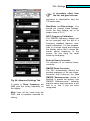
A secondary effect from
the lab, and good to know:
Activation or deactivation trips the
T/R switch relay.
Bias/Slider and Bias-voltage: You
should not change these settings.
Leave the bias voltage set to its
proper value of 2.5 V.
Si570 Frequency Calibration:
The PMSDR frequency display can
be set precisely with the aid of a
frequency standard (beacon, timesignal transmitter). For this purpose,
tune to a known signal and change
the display value until it shows the
known carrier frequency of the
source. Do this using the small
button by the display.
External Down-Converter:
For activation of an external downconverter.
Fig. 96: Advanced Settings Tab
A check in Show Frequency on
LCD puts the tuning frequency on
the display.
PMSDR Down-Converter:
The DLL automatically detects the
possible presence of its own downconverter. Until it does so, the Use
PMSDR Downconverter choice is
blocked. A grayed out legend “Use
PMSDR Downconverter“ indicates
that the native down-converter is not
built in or that it has not been
recognized.
Mute turns off the mixer from the
QSD, and is therefore reserved for
testing.
47
DLL Settings
Simultaneous
Converters:
In the presence of the native PMSDR
down-converter, you should never try
to also activate an external
converter. This also applies to the
3rd harmonic mode. If you intend to
use this mode, do not activate the
external converter.
IF-Panadapter:
In reading the next paragraph, where
the example illustrates how to deal
with the PMSDR as a panadapter
you will find an extensive explanation
of the subject of IF Pan-Adapters.
(See panadapter settings).
Mixer inv.:
Is a function that you select
depending on RX/TX status as well
as sometimes with an IF board, since
a few IF boards invert the signal
layer. This occurs, for example, with
the Elecraft K3 and requires use of
“Mixer Inv.“
Switchboard:
If this option is in operation, it allows
one to set a PTT drop-out delay, in
ms.
“Only
SSB/CW“
should
preferably be used with the internal
RF VOX of the switchboard.
Use of this switch is only meaningful
when hardware PTT-control is not
used. If you use the PTT control
output of your TRX, set the delay
value to zero.
48
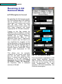
3th Harmonic Mode:
Another section is dedicated to the
experimental mode called 3rd
harmonic mode
.
Reception up into the VHF range (to
165 MHz) is possible, using the 3rd
overtone of the local oscillator. There
is some loss in sensitivity, but
operation in this way does not
require addition of a down-converter!
Auto-Select This mode switches in
automatically, when a frequency over
55 MHz is specified.
Save Current
Default:
Frequency
as
This does exactly what it says: The
current frequency is used each time
the PMSDR is brought up.
The special significance of
this application becomes
clear, for example, when using the
PMSDR as a WEB SDR receiver
[16,17]. Here, the USB interface only
serves as a power supply. This
setting insures that the PMSDR
comes up with the default frequency
every time it boots!
DLL Settings
You will better understand the CAT
settings under the final tab, when you
read the explanation in the
subsequent paragraphs concerning
“daily usage.“
All these settings control the data
direction and data flow when used
with a transceiver.
Enable CAT:
Enables firstly the bidirectional data
flow between PMSDR and the
TRX. Specifically here we mean the
flow of data from TRX to the PC
software.
Send CAT commands to Rig:
Contrariwise this influences data flow
in the reverse direction, namely from
the PC-Software to TRX. You use
this
function
specifically
in
panadapter mode. The following
section elaborates on this.
Use RTS:
when activated, sets a voltage on the
RTS line of the RS232 port of your
PC. This option may be needed to
supply power for an interface
converter or interface. The various
offset settings provide a very precise
synchronization between the RX /
TRX-VFO frequency and the display
of the PMSDR in panadapter mode.
If you don’t work in panadapter mode
(but rather in direct receive mode)
then use Enable Offsets to turn this
off.
Fig. 97: CAT Tab
Write Tune to RIG:
Transfers the selected frequency to a
TRX if one is to be used, as already
described above under Quick Tune.
The two functions are the same.
49
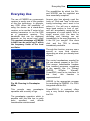
Everyday Use
Everyday Use
The possibilities by which the DLL
and HDSDR can be exploited are
here essentially complete!
The use of PMSDR as a panoramic
receiver is surely one of the goodies
of this fine technology. In principle,
any SDR offers the possibility of
using the device as a stand-alone
receiver, or to use the IF output of an
existing transceiver to run the SDR
as a panoramic receiver. The
bandwidth that can be displayed
depends on the sound card used!
The greatest advantage of PMSDR
is that it can be set to any IF within
the frequency limits of the local
oscillator.
Anyone who has already used the
luxury of “Click and Tune“ in this new
tuning technology won’t want to be
without it. You will see a relatively
large band section in front of you,
and will immediately recognize the
emergence of a new station. With a
single mouse click, the bars for
decoding and listening are set
immediately to the new frequency. Is
it the DX you sought? One more
click, and the TRX is already
immediately available.
Through this function, one may use a
second or even third receiver,
depending on what you already have
at hand.
The control mechanisms needed for
this are already present in the DLL.
That means considerable freedom
from installed programs, regardless
of the specific one (i.e. Winrad,
HDSDR,
WRplus,
WinradF,
PowerSDR) used as an interface. In
this
form,
this
freedom
is
unprecedented!
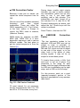
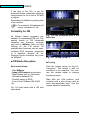
Fig. 98: Running In Panadapter
Mode
This permits easy panadapter
operation with a variety of rigs.
The panadapter operation which is
possible with this little box is really
quite
excellent,
and
affords
considerable entertainment!
50
HDSDR is the appropriate program
for controlling the PMSDR. It is 100%
integrated with the DLL.
PowerSDR-IQ, in contrast, offers
only a very limited integration with
the DLL.
Everyday Use
In what follows, you will see a
description of the use of a FT9502000 in this regard. For all other
transceivers, see below for a
summary and for the information
needed to convert a FT-950/2000 to
this functionality.
What is described here is naturally,
mutatis mutandis, as much for
normal HF reception as for standalone mode.
The board will be installed at the
location allocated for the DMU2000
unit in this device. The amateur radio
market has the relevant boards in
stock. On behalf of all others, we
mention [4] here.
.
Installation is very simple and only
takes a few minutes. It does not void
the guarantee. One needs nothing
more than a screwdriver and a small
cable tie. Installation should not be a
concern.
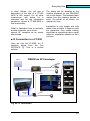
■ IF Connection to a FT-950
Here we use the IF-2000, an IF
interface board from the firm
RFSPACE [2]. This is a proven
solution.
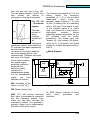
PMSDR als ZF-Panadapter
Antenne
IF- Out
CAT Interface
Soundcard
Line In
USB
Fig. 99: IF Connection
51
Everyday Use
The Installation Guide that is
delivered with the IF board explains
everything very clearly.
The vents on the rear of the unit are
used to route the supplied coax cable
to the PMSDR. A small cable tie is
■ Tandem Mode
with the FT-950
Hookup
This is only protected against
damage to the input stage when you
use the optional T/R (switchboard)
PMSDR & Switchboard Option im Tandem - Mode
PTT control
Ant. (max100W)
CAT Interface
Soundcard Line In
USB
Fig. 100: Tandem-Mode
used to attach the coax to the vent
fins. In addition to connecting to the
IF port, it is also possible to use the
PMSDR as a separate receiver at the
same time. We refer to this as
“Tandem“ mode. It is illustrated in
Fig. 100.
Connect the IF cable to the antenna
input of your PMSDR per Figs. 99
and 100.
52
switch. The antenna signal (for
sending and receiving) is routed via
this board. In this case, a max. 100W
output power (up to 50 MHz) is
allowed. The PTT line of the TRX
takes over secure control of the
circuit board.
Everyday Use
Do not confuse PTT In and
PTT out!
Do not become
confused by the normal PTT jack on
your transceiver (PTT-In), sometimes
used with a foot switch.
This is a jack for an input signal
(switch-contact to GND), and is not
suitable as a control input for PTT
control of the switchboard.
Remedy:
Use the hardware control signal that
is present, for example, in the control
socket for an external power
amplifier (PTT-Out).
Alternative:
Equip your foot switch with a second
microswitch, and use it for hardware
control of the switchboard.
■ CAT-Connection
yet. Now we will configure the
software so that the interaction
between hardware and software
works smoothly. Essentially, it is only
the DLL that needs to be processed,
in graphical form on your screen
when you start HDSDR. You will
recognize the picture from the above
material.
Please
verify,
by
comparison with the website [1], that
the current DLL is loaded.
■ Interdependencies:
Send/Receive Direction (of
the CAT signal)
For a better understanding of the
following, note that “ENABLE-CAT“
is meant to activate the CAT
connection in general, as well as
here specifically to direct the data
flow from the transceiver to the PC
software!
Figs. 101 and 102 clarify this.
In both cases, we need a CAT
connection between the PC and the
TRX. A simple 1-to-1 cable will be
sufficient. The cable must not be
crossed internally at the plugs, and
each end needs a 9-pin female
RS232 connector! (This is NOT a null
modem cable!)
A USB-RS232 converter [1] may of
course also be used here.
■ Configuring HDSDR
All the information in the following
applies equally for both modes,
tandem, or IF configuration. Boot
HDSDR [9], but do not press START
53
Everyday Use
the entire operation in telegram style.
Best to print it out and keep it handy.)
PMSDR & Transceiver & Winrad
■ CAT Settings
Winrad steuert das
PMSDR, als auch den
TRX, via CAT Interface.
All settings described here refer to
the DLL v3.3 Rev2. Check the web
site [1] for the list of supported TRX
and for new versions.
CAT-Interface
The necessary parameters for
control of the interfaces to and from
the RIG, as well as the data for
Frequency Offset (described later)
are initially entered under the CAT
tab.
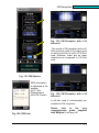
Fig. 101: Enable CAT ON
Remote RIG OFF
Before you can use ADVANCED
SETTINGS to switch on the
panadapter, you must set up CAT
control fully.
PMSDR & Transceiver & Winrad
Mit Hilfe des Cat-Interfaces
steuert der TRX sowohl das
PMSDR, als auch Winrad.
CAT-Interface
Fig. 102: Enable CAT ON
Remote RIG ON
Please note the entries marked with
the yellow arrows!
Activation
of
“Send
CATCommands to RIG“ however, opens
the transfer direction for all the
commands in the direction of the
TRX, for example for writing a
frequency to the VFO of the TRX.
You will learn below just what we can
accomplish by clever activation or
clearing of this check box,! (The
Appendix contains a description of
54
If
ENABLE-CAT
is
checked,
uncheck it, otherwise you will not be
able to make the necessary changes.
Replace the COM port number
shown in the box by the COM port
number you are using for the TRX.
Everyday Use
This always works in the usual way,
even with the “Remote Rig“ flag
switched off (meaning „Send CAT
commands to RIG“.)
If you leave this function switched on,
and press “Write Tune To RIG,“
although the frequency will transfer
to the VFO, the spectrum displayed
will simultaneously change, which we
don’t desire to happen (read further
under ■ Initial Operation)
For „normal“ “Click and Tune“
operation, the statement reading:
Send CAT commands to RIG
should be left switched off!
The currently used offset value is
shown in green, and again explicitly
specified in the box CURRENT
OFFSET. We will go into “Offsets“
again later.
So, now set ENABLE-CAT to on
again, and go to the ADVANCED
SETTINGS tab.
Fig. 103: CAT Settings
Now
on
to
configuration.
the
panadapter
Use the menu in your TRX to set the
baud
rate
and
handshaking
(RTS=Off) to the values visible in the
CAT settings. For the FT-950, use
positions #26 and #28, which
correspond to these settings. (If you
use a CAT interface or a USBRS232 converter instead of an
RS232 cable, you may have to turn
on USE RTS to provide power to the
adapter. Check in the manual of your
CAT interface.)
Using the Write TUNE RIG
button, pass the selected frequency
on from the waterfall to the TRX with
a mouse click.
55
Everyday Use
■ Panadapter Settings
In the Box IF Pan-Adapter under the
Advanced-Settings tab, select, under
RIG, the IF-Board IF2000. The
required IF of 10.55 MHz should be
selected automatically, appearing in
the adjacent field.
how to make the entry quickly and
easily.
Now check LOCK PMSDR ON IF.
This locks the local oscillator of the
PMSDR to the IF of the FT950/2000.
SHOW FREQUENCY ON LCD
should also be enabled. If so, the
TUNE FREQUENCY for HDSDR is
also shown on the PMSDR LCD
display, if the display option is
present.
If you now press START in HDSDR,
you should already have a spectrum,
or see a waterfall with information,
provided all your basic settings for
HDSDR are OK.
■Initial Operation
Fig. 105: Active 80m Band
You can now use HDSDR to decode
stations that you see in the waterfall
by clicking on them.
Fig. 104: Advanced Settings
(If the entry for IF2000 does not
appear, go briefly to the section on
manipulating the DLL. This explains
56
There is one important difference to
the stand-alone mode, in which the
PMSDR up to now has been used
Everyday Use
as a stand-alone receiver.
In this mode, you simply put the lightblue
tuning
bar,
hereinafter
abbreviated cursor, on the station to
be decoded, then the next, etc. etc.
Here, the LO correctly follows the
tuned frequency.
RIG, as we have already mentioned
above!
■ Listening to Stations
Now return to the CAT tab, and
deactivate the check box for: SEND
CAT COMMANDS TO RIG. (This
switch is found in Remote Rig.
Because of the shorter spelling, this
term is hereinafter to be used as a
synonym. “Remote RIG OFF“ thus
means that “Send CAT commands
to RIG” is NOT activated!) This
prevents the continual alteration of
the spectrum when the cursor is
moved.
In the display area, you can now click
around at will, seeking out stations to
decode and to click on for listening.
The TRX is temporarily possibly
tuned to a different station, until a
new frequency is written into the
VFO using Write TUNE RIG.
Fig. 106: Remote RIG OFF
If the previous settings were done
correctly, you will see that HDSDR
always transfers the new frequency
to the RIG, and that the waterfall and
the spectrum also change in
appearance with every click.
The presently blue-backgrounded
QUICK TUNE tab is an indication,
that functions there are no longer
accessible. Switch to the QUICK
TUNE tab provisionally. The whole
internal field is now displayed in red
to show that these functions are
disabled.
Of course this is not so useful, nor
really intended, and because of this,
we now have to turn off the CAT
connection from Program to
57
Everyday Use
Now is the time to explain the next
step for applications, namely what to
do if you want to want to leave or
change the display area.
■ Changing the Display- or
Frequency-Range
There are various possibilities:
I.) If you simply turn the VFO knob
without changing any of the settings,
you will see that the light blue
frequency bar changes, and the
spectrum in the display frame
changes as well. Pick out new
stations as usual, just by clicking on
them.
II.) Use the TUNING STEPS/ FAST
TUNE, along with the ± Button
under the QUICK TUNE tab.
III.) Select the bright blue frequency
bar with the left mouse button, hold it
depressed, and slide the tuning bar
to the right or left to a frequency
range of your choice. Do this as
many times as you please, by
releasing and pressing the frequency
bar to a new position, etc. etc.
The latter two versions will obviously
require the reactivation of the
function SEND CAT COMMANDS
RIG. How else would the TRX else
know that it has to adjust the VFO?
Re-check the box for RIG control,
that is: RemoteRIG ON.
When you do this, the blue field in
QUICK
TUNE
simultaneously
disappears, and the same interior
legend changes color to green.
58
Fig. 107: Remote RIG ON
Access to the control is released
again!
Please try out options II and III! The
proof is in the pudding here!
The operation sequence is logical
and will become familiar to you very
quickly.
Reading this description makes
things sound much more complicated
than they are in practice.
Everyday Use
So please, no hesitation. Operation
will quickly become “duck soup.“ The
fact that here in Quick-Tune a single
click also allows you to change
bands, is surely clear to you and
requires no further mention?
Incidentally, the built-in ability of
HDSDR to change bands (BAND
button) works the same way, and
allows either/or/simultaneous use of
the DLL-functions!
Along with band change, the mode
(USB, LSB, AM, CW, etc.) also
automatically switches over.
Which modes are used for each
band is stored in the INI to the DLL.
You can use an editor to make as
changes as required.
■ Setting Mode-Offsets
We come now to a most interesting
part of this manual, namely the
precise transfer of the selected
frequency to the VFO of your TRX by
mouse click.
At this point you have to know that
the
IF generated by the FT950/2000 is not carved in stone, but
that it changes with the selected
operating modes (USB, LSB, CW ...)
and possibly the programmed carrier
offset. These expected changes lie in
the range of ± 3 kHz. This is not a
negligible
change.
Without
a
correction factor in PMSDR which
gets passed to the VFO, the
frequency would deviate by this
amount from the receive frequency of
the HDSDR spectrum.
As a consequence, one would simply
not hear/find the expected station
and therefore also not be able to
communicate!
This is the reason for the presence of
mode offsets.
These values only need to be
determined once, and written into the
Mode Offset boxes using the small
up / down buttons.
This process ultimately calibrates the
frequency display in HDSDR to the
VFO of the RIG! We will explain how
to do this in a moment. If you wish, at
this point you can just use the predetermined correction values for the
FT-950:
CW
+ 1.300 Hz
USB
+ 2.700 Hz
LSB
- 200 Hz
AM/FM
+ 1.160 Hz
Fig. 108: Offset Values for the FT950
These numbers will not be badly
wrong, at least for a FT-950.
The precision of the renewal of these
numbers on HDSDR re-launch is
quite good.
One ends up so near the VFO
frequency that the signal set in
HDSDR is easy to identify in the
VFO.
There will possibly be (small)
corrections to be made with the VFO
knob, so that one, by ear, gets the
same pitch as in HDSDR. These will
be of the order of magnitude of a few
Hertz.
59
Everyday Use
■ Determining
Factors
Correction
How do you determine the best
correction factors? This is also very
easy and quick to understand, and
will be explained in steps. The goal is
to match the HDSDR frequency to
the VFO frequency of your RX/TX!
The simplest of these cases is the
equalization for AM and CW,
because both can be matched to the
existing transmitted carrier itself. An
example based on the DeutscheWelle can be used to illustrate this:
■ AM Correction Factor
Frequencies of 6075 kHz and 6190
kHz almost always offer good AM
reception. We begin with the AM
case; tune your VFO to one of these
frequencies with the CAT and
REMOTE RIG on. The following
figure shows a piece of the spectrum
around the frequency 6075 kHz, as it
comes from a display width of 96 kHz
and RBW = 93.8 Hz.
In this case, you want a resolution
sufficient to
allow the precise
positioning of the cursor on the
carrier frequency.
Fig. 110: Centering (RBW 5,9Hz)
Just choose the maximum resolution
of RBW = 5.9 Hz (for each screen
pixel (2)). Press and hold the
corresponding Up/Down button until
the center peak of the carrier
matches the desired frequency.
The waterfall picture shows clearly
how the carrier slowly but surely
moves in the direction of the desired
frequency. Center the peak with the
Up/Down buttons as precisely as you
can. If the whine of the carrier
bothers you, just shut it off with
MUTE.
Done! that's it for AM! That was not
really so hard, right?
Fig. 109: Display for 6.075 MHz AM
The match is almost perfect, when
using the correction values. If,
however, you start with zero entries,
the evident differences are of course
much larger.
60
Everyday Use
■ CW Correction Factor
Because it was just so simple, we
repeat the whole sequence now for
CW.
We use one of the available standard
frequency
and
time
signal
transmitters. These are either the
WWV transmitter (U.S., Fort Collins),
or the best station in Europe to
record, the RWV chain of stations,
(Moscow, Russia).
RWM sends, for example, on 4996,
9996 and 14996 kHz in a timedependent sequence, and in various
different modes. The best place to
get the actual sequence is from the
internet [8].
During these roughly eight minute
intervals, we see a carrier without
any modulation, which can be very
easy to use. If you don’t hear
anything, wait a few minutes. The
transmitters are each turned off in
the minutes 8 to 9, also 38 to 39!
Proceed analogously as above, and
adjust the Up / Down keys until the
carrier is centered.
Done! That's it, this time for CW!
■
LSB/USB
Factor
Correction
The two remaining modes to be
adjusted, LSB and USB, are just as
simple to treat, in principle. In
practice, it is not quite as easy as for
AM and CW, since one has to adjust
to one side of the signal, or to the
other, both in the welter of other
existing signals. It may not be so
simple to locate these points.
To locate these points, a little “trial
and error“ is not out of place. The
procedure is the same for both
modes, with the single difference that
for LSB one is calibrating on the right
edge, and in USB on the left edge.
For this process, seek out a quiet
(sparsely-occupied) portion of the
spectrum somewhere in any amateur
radio band.
Fig. 111: CW Carrier Centered
Of most interest for our purposes,
are the transmissions from 0 to 7:55
and 30 to 37:55 minutes, every hour.
61
Everyday Use
Set the audio from the rig and
HDSDR to a comfortable level, and,
analogous to the above, use the
Up/Down buttons until the two audio
signals are as nearly as possible
identical.
It is naturally not a question of „zero
beat, but the process is very similar,
and every technolog immediately
understands what is meant here!
You don’t need to use the highest
possible resolution here, as the
adjustment by ear has a somewhat
subjective character.
Fig. 112: LSB Calibration
Tune the VFO so that the received
speech sounds natural to your ears.
IF we now set the HDSDR
Frequency to the VFO Frequency,
we are using as an indicator one of
the best measuring instruments that
we have as radio amateurs, namely
our ears.!
In the future, for everyday use try to
set the cursor (more precisely, the
red line next to the tuning bar) on
the corresponding signal flank as you
are now doing, and remember this as
long as possible.
This ensures that every time you
click, you will get a correct VFO
frequency for the transmitting station!
However, if you are not quite on the
VFO frequency, this is not the end,
because you always end up at least
pretty close. (As described above,
always somewhere in the range of a
few Hz)
A small turn of the VFO knob if
necessary, and you have the right
frequency!
That’s it! With this, you have set all
the offsets!
Fig. 113: USB Calibration
62
Everyday Use
■ Storing the Values
An important point must not be
overlooked, namely saving (storing)
the above-determined values!
There is, unfortunately, no extra
button for this in the DLL; you just
have to remember, that writing /
saving the values to the INI of the
DLL happens at the moment when
you press the STOP button in
HDSDR!
You should therefore not get used to
terminating the program with the Red
Windows Close Box in the top right
corner of the screen. Always
terminate the program properly by
using “STOP and EXIT.“ Now you
know why ...!
63
Manipulation der DLL
Possible Ways to
Manipulate the DLL
The DLL file itself cannot be
modified. Influence over the various
parameters associated with the DLL
is only allowed via the so-called INI
file. The parameters in this file are
read at startup of HDSDR in the DLL.
The result will appear as a service
window next to HDSDR, in the
graphic form you already know.
The
INI
file
is
called
EXTIO_PMSDR.INI, and is a purely
text file, which you can work on using
an appropriate text editor. The term
"manipulation" is chosen with care
and intention. Warning: When one
enters something here, he must
understand clearly that he is
"manipulating" the file!, After all, this
is
the
control
file
for
the
EXTIO_PMSDR.DLL, the heart of the
software interplay between PMSDR
and HDSDR, as well as the rig that is
connected!
brackets in the original file. After
saving changes and executing a cold
restart,
any
changes
are
automatically transferred to the DLL.
■ IF Entry for use as a
Panadapter:
The relevant original entries look like
this:
[PAN_RIG]
ELEKRAFT K2=4915000
ELEKRAFT K3=8215000
IF2000=10550000
In this example, you will note an
entry for the IF-2000 interface board
from RF-Space mentioned above..
This is an IF interface for the Yaesu
FT-950/2000, which down-mixes the
IF of the two devices to the level that
PMSDR can use without problems.
(In this case, to 10,55 MHz) This
saves one from the outrageously
expensive DMU unit.
For your own entries, copy this
example.
Backing up the file
BEFORE changing it is strongly
recommended!
■ Target for Changing Quick
Tune entries:
Use a suitable text-editor for editing.
Notepad2 [15] is available as
Freeware, and is excellent! Below,
we specify sections for changing or
supplementation in the *.INI file.
These sections are also found
enclosed in square
[BANDBUTTONS_FREQ]
LW=150000
MW=500000
160m=2000000
120m=2300000
90m=3200000
80m=3800000
75m=3900000
64
PMSDRP
PMSDR
You can cleverly arrange things so
that a click on the 80 meter band
jumps you immediately to the
(hopefully DX-loaded) upper band
edge. From there, the band lies in
the direction of lower frequencies. If
you are more interested instead in
CW or digital modes, you can
accordingly naturally set up the
corresponding... etc. etc.
■ 3rd Harmonic
Automatically...:
Mode
■ Changing the way QUICK
TUNE works...
&
■ Creating Additional QUICK
TUNE ENTRIES...
The adjacent QUICK-TUNE window
clearly illustrates how to get to your
favorite bands and areas by mouse.
One must, however, make
absolutely sure now that the
same name is used in all three of the
areas:
[BANDBUTTONS_FREQ],
[BANDBUTTONS_TUNESTEP],
[BANDBUTTONS_MODE],
Very clearly you can do this with the
help of an Excel file.
One can see at a glance if something
is wrong somewhere! Compare Fig.
115!
Fig. 114: Quick Tune Entries
When one keys VHF/2m into the
auto-select
function,
the
unit
automatically switches to the 3rd
harmonic mode (SS67)!
65
Manipulating the DLL
Remember that all three areas need the same name; otherwise nothing will
come of your project! The figure below shows in a row, for example, the name
80m Digi 3x. This name must be the same in all three columns!
FREQ
TUNESTEP
MODE
Fig. 115: Entries for Editing Quick Tune
■ Sked Entries adapted to your
needs:
[SKED]
FILENAME=beliebig.csv
SHOW_LCD=1
LANGUAGE=All
66
The original entry sked-a09.csv
contains a text file (it is a pure text file,
even though its name doesn’t carry
the extension *.txt!) with pretty much
all short-wave radio stations, which
can then be received under SKED,
only requiring a mouse click. The
unchangeable default mode here is
set to be AM. Eike Bierwirth
(evidently the source of the name
“EiBi “), from Leipzig, is the author of
this nice addition.
Everyday Use
You can find the newest *.csv file on
his webpage [13]. Just copy it as
needed into the HDSDR program
directory.
Use the Open Database function to
make the file selection you desire.
An example:
The following text is entered under
the file name oe8mcq.csv, which is
then called through Open Database
in the DLL:
The accompanying text is shown,
reproduced line by line.
1:kHz:75;Time(UTC):93;Days:59;ITU:49;
Station:201;Lng:49;Target:62;Remarks:1
35;P:35;Start:60;Stop:60;U1018-RUS
2:14070;;;;20m PSK-31;x;AFU;;;
3:27065;;;;CB-Ch.9;x;CB;;;
4:29670;;;;10m DF0MOT;x;AFU;;;
5:50110;;;;6m SSB-CALL;x;AFU;;;
Fig. 116: Installing your own „Sked“
The structure of this file is somewhat
complicated. Nevertheless, you can
pretty much adapt it to your own
needs.
There is a total of five lines, the
structure of which must be exactly as
listed here, otherwise the DLL will not
function properly.
Line 1 is especially important, and
must not be changed in any case!
Do not use bold-face numbers 1-5
when you type them.
Line 1: Your own entry via the editor
begins with "kHz" and ends with "RUS".
Line 2: starts with "14070" and ends
with "AFU ;;;\", etc.
The number of semicolons is
important!
Their
exact
number and arrangement is
important!
By the way, all the example files
mentioned in this manual are to be
found in the appropriate subdirectories on the enclosed CD as
well.
67
Manipulating the DLL
As selection criteria in this example,
the terms amateur radio and CB are
installed. Other additional words are
possible, after using the Language
and Target filters to make a filtered
version of the original language.
The mode is, as already indicated,
limited to AM.
If necessary, simply switch the
required operating mode by hand.
The illustration Fig. 116 ends with
Lang. Everything else is hidden on
the right. Using the slider at the
bottom of the screen, scroll to the
desired display area.
■ External Down-Converter
[DOWNCONVERTER]
2m=116000000
70cm=404000000
Two entries for 2m and 70cm are
already loaded with the LO values of
116 MHz and 404 MHz.
If these values do not correspond to
your LO frequencies, you can
change them as necessary. You may
also like these records kept as they
are, and may add your own as long
as they conform to the illustration.
Your new entries will appear in the
drop-down list at the next start-up for
you to select!
Fig. 117: Ext. Down-Converter
68
PMSDRP
PMSDR
Receiving in 3rd
Harmonic Mode
■ FM Reception in General
By activating the 3rd harmonic mode,
the FM broadcast band (88-108MHz)
can be received with a 192 kHz
sound card. The receiver also works
with 96 KHz cards but with
somewhat limited sound quality. 48
KHz cards however are totally
inappropriate for FM radio reception.
Turning on this flag causes the
PMSDR to be set exactly to one third
of the desired receive frequency. The
PMSDR has a lower sensitivity
(approximately-108 dBm, in 3rd
harmonic mode; that is, 15dB poorer
than in normal use), but that is not
very significant for reception of the
strong channels in the FM broadcast
band. Note that the PMSDR after all
still has an IP3 of +30 dBm with a
dynamic range of 92dB IMD. (These
values were determined at 144
MHz.)
This allows one, for example,
reception of the aircraft radio band
and the 144 MHz amateur radio
band. It should be noted that the
spectrum of the 3rd overtone is
backwards. By inverting with "SHOW
OPTIONS"->"Swap I/Q channels"
the frequency scale is displayed
correctly in Winrad.
Uncheck!
Uncheck!
Fig. 118: 3rd Harmonic Mode
This has particular implications in FM
narrow band operation (amateur
radio to 20 KHz), since the frequency
scale will not be precise. For the
much broader-band FM radio
operation (150 kHz bandwidth), this
is almost meaningless.
69
PMSDRP
PMSDR
If the flag in the DLL is set for
automatic mode, automatic switching
occurs when the LO is set to 55 MHz
or higher.
Remember to disable everything that
is not needed.
For example, Pan-adapter-off
mode, converter off, etc.
Suitability for FM
All Winrad based programs are
suitable for narrowband FM use. The
special needs of FM broadcast
reception are, however, currently
only met by WRplus. Here, by right
clicking on the FM button, all
sophisticated functions can be seen,
including RDS reception, presented
in a separate window! All the
following figures therefore only bear
on WRplus!
Fig. 119: FM Reception with a 192
kHz Card
■ FM Radio Reception
■ Tuning
Brief Instructions:
Click the mouse cursor on the LOFrequency. This marks it with an
overscore or an underline. You now
use the mouse wheel to change
frequency easily.
- Start WRplus,
- Swap I/Q-Channels is irrelevant,
- Right Mouse click on FM button,
- Activate broadband FM.
- Possibly switch in RDS...
- Tune in the FM Band (88-108 M
Hz).
Fig. 119 was made with a 192 kHz
soundcard.
70
Fig. 120: Tuning using LO
Start with the 10th position, and
continue with a new mouse click at
each less-significant digit. Use the
mouse wheel as necessary.
FM Reception
Fig. 123: FM Reception with a 96
kHz card
The sound of FM reception with a 96
KHz spectrum card is no longer quite
so strong and full as with a 192 kHz
card. However, there are no other
restrictions as compared to 192 kHz
card.
Fig. 121: FM Options
RDS information
is displayed in the
window.
(± 57 KHz
Displacement
from FM Carrier)
Fig. 124: FM Reception with a 48
kHz card
A 48 kHz card is unfortunately not
suitable for FM reception!
Fig. 122: RDS Info
Please
refer
to
the
very
comprehensive guide supplied
with WRplus! It will pay off!
71
FM Reception
■ FM Reception in Amateur
Radio
Brief Instructions:
- All Winrad based programs are
suitable!
- Start HDSDR,
- Switch Swap I/Q-Channels,
(Contrary to your previous Settings for
LSB/USB Reception!)-
- Click on FM button,
- Tune in the FM portion of the 2m
Amateur band (146-148 MHz)
- Work with LO in Reception Mode,
and tune using TUNE.
There is really not much more to say
here, as everything has already been
explained.
With exception of the bandwidths,
the screen pictures are quite similar.
This (narrow-band FM) is also the
reason for the universal applicability
of all Winrad derivatives.
■Air Traffic Radio Reception
(AM)
Brief Instructions:
The same situation pertains as in the
two examples above, but with one
exception:
You must switch to AM mode, as all
air traffic takes place using AM!
- All Winrad based programs are
suitable!
- Start HDSDR,
72
- Switch Swap I/Q-Channels,
(Contrary to your previous Settings for
LSB/USB Reception!)
- Click on the AM button,
- Tune in the Air Traffic AM Band
(108- 136 MHz),
- Work with LO in Reception Mode,
and tune using TUNE.
PMSDRP
PMSDR
Sample Applications
■ DREAM
© 1998 DRM-Association
DRM stands for Digital-RadioMondiale, which is most simply
understood as “Worldwide Digital
Radio.“. This public service includes
digital radio and data services. The
data are encoded for transmission
using MPEG-4. DRM works in the
shortwave region, with a bandwidth
of 10kHz.
The DRM mode in the various
versions of Winrad does not decode
the signals, but just broadens the
bandwidth to 12 kHz. If you wish to
continue to work with the possibilities
that Winrad offers, must provide a
decoder. This can be accomplished
elegantly today with VAC (Virtual
Audio Cable). With the help of VAC
[19], Winrad passes the data stream
to the desired program. Here we
focus on the description of the standalone version of the program.
Fig. 125: Dream
DREAM is an example of such a
program, developed at the University
of Darmstadt by Volker Fischer and
Alexander Kurpiers. This program in
in the public domain. [20]
■ DREAM as a stand-alone
program
On the CD provided, you will find the
current version of DREAM (up to the
time of printing of this manual),
Version ver. 1.61. The program
requires no installation, and is started
using its program name, dream.exe.
It is best if you install a start-up icon
on your desktop.
An alternative to VAC is to use a
special program for decoding the
signals.
73
Sample Applications
You will usually have to use the
command line tag “-c5“ when you
start the program, in order that
Dream runs in I/Q mode. To set this
up, open the “Properties“ menu with
a right mouse click on the Dream
icon.
One is the so-called Evaluation
Dialog, the other the MultimediaDialog.
Both windows are from the main
program.
What we need
now is a system
for setting the
frequency.
Somehow we
need to tell our
PMSDR what
frequency we
would like to set.
Fig. 126: Program start line
The tag –c 5 needs to be entered
after the exclamation point.
There is a small
utility exactly tailored for these
applications that allows you direct
frequency input using a mini-DLL
In the root directory of the CD, find
PMSDR-Control_v1.5 and start
pmsdr.exe from there.
Fig. 127: Sound Card Selection
Under Settings and Sound Card
Selection, enter your current data for
audio input and output (Sound-In /
Sound-Out).
When your program is running bring
up two additional windows on the
screen by pressing Ctrl-E & Ctrl-U .
74
As a result, two windows open up.
One allows direct frequency entry by
clicking the numeric positions.. The
other has a graphic interface already
known to you for the DLL. With the
numeric input, you already have
complete control.
Sample Applications
Fig. 129: Decoding OK
Fig. 128: Frequency Input
Notice what is written in the window:
“Click & tune with the Mouse wheel“.
A click on one of the large grey digits
permits
quick
frequency
change/entry with the mouse wheel.
The DLL permits convenient direct
access to your desired frequencies
even with CAT control.
These can be found under the
Quick-Tune tab, and under sked.
Entries are of course possible, as
already described above in the
section on manipulation of the DLL .
Fig. 130: Quick-Tune Window
If your current waterfall shows a
strong signal as well defined as the
well-defined signal in Fig. 131, but
nothing is heard, then it is highly
probable that the receive selection
must be inverted.
The multimedia dialog shows several
active DRM frequencies, and among
them, 7325 kHz promises quick
reception success.
75
Sample Applications
It should now be
possible to hear
a nearly FM-like
language or
music output!
The Disco Palace promises just as
easy a reception experience on 6015
kHz.
The Russian service Label Service
very often broadcasts in German on
7325 kHz, and we usually receive it
well in Europe.
Fig. 131: Flip Input Spectrum
In this case, check the Flip Input
Spectrum box. Leave all other
settings as they were. If the inversion
of the reception sspectrum produces
the desired results, put the tag “-p“
into the previously cited program call.
This permanently sets the check in
the „Flip Input Spectrum box. In the
properties box for program startup,
the complete call now reads “-c5 -p“.
76
The program needs a strong input for
clean reception. Feel free to
experiment a bit with different input
levels for your sound card!
Have fun with DRM Reception!
PMSDRP
PMSDR
■ PowerSDR-IQ
Installation:
If you just happened to start
reading the manual here:
Don’t necessarily begin your career
with Power SDR-IQ.
If possible, install the program using
all of its “Default“ values. Then copy
the three necessary DLL files into the
newly created program directory.
It is a very nice program with lots of
capabilities, but it is exactly these
that make the program less obvious
in contrast to the Winrad versions,
and somewhat unwieldy to use. In
addition, the original PowerSDR was
actually specifically designed for Flex
Radio equipment, and is exactly
tailored to that in operation.
Consequently, when used to control
PMSDR many buttons are useless
because they are inactive.
(If you need the full program path, for
XP this is in C:\ Program Files\ Flex
Radio\x26
SV1EIA\
PowerSDR
v1.12.23-IQ\) For Win7: Instead of
“Program“ use “Program Files“.)
Good to know:
There are several PowerSDR-IQ
systems on the internet. On the
CD, you will find ver. 1.12.23,
which has proven to be stable.
These are the three files: c3260.dll,
Extio_PMSDR.dll, and
mpusbapi.dll.
Be careful not to use
the file Extio_PMSDR.dll
accidentally for one of the Winrad
derivatives. It won’t work!
Start the program and click on
Setup.
More recent versions (since
v1.19.xx) no longer support the
necessary PMSDR DLL functions,
and are therefore no longer useful.
These versions require a
particular version of the DLL: ver.
3.2 rev. 9. This supports the
PowerSDR-IQ software to version
v1.12.xx.
Fig. 132: Setup
In the resulting window, put your
general and hardware config in the
foreground..
77
PowerSDR-IQ
The familiar DLL
control window
immediately
appears on the
desktop!
In the next step,
the necessary
audio installations
will be carried out.
You find these at
Audio and
Primary, as are to
be seen in Fig.
135
Fig. 133: Radio Model Setup
Activate the radio buttons at
Radio Model, and also at
Receive Only.
If you should happen to find your
card entered here, please please do
not select it!
Now open the tab General ExtIO.
In this new field, activate PMSDR
Enable.
The reason has already been
mentioned above: This is a function
that necessarily implies the Flex
radio hardware! This would therefore
definitely lead to problems! So
please leave this item set to
Unsupported Card!
Fig. 134: Enable PMSDR
78
Winrad Variants
The CAT control missing from
the DLL is done internally by
the PowerSDR-IQ software.
Only activation of CAT control
subsequently then allows the
use of the band and mode
switches as shown in Fig. 136.
Fig. 135: Audio Settings
Make all the important settings
shown here, insofar as your sound
card allows..
Various
different
drivers
are
concealed behind the Driver pulldown menu. First, try the standard
driver, MME. Move on to others only
if you don’t see a waterfall in this
case.
Fig. 136: Band and Mode Button
Please therefore, use the settings
that you see in Fig. 137.
Only Enable CAT
PowerSDR.
and ID as:
We have already pointed out:
A special DLL is required here, which
offers many possibilities not available
in Winrad!
Everything else is uninteresting, as it
is associated with external hardware.
Thus, for example none of the entries
Quick-Tune, Sked, CAT will be
available.
79
Winrad Variants
The DLL in Fig.
139 is already
familiar. It offers
no other special
features over what
you already know.
Fig. 137: Set Up CAT
The switch “Allow Kenwood AI
Command” is probably more closely
related to other interactive programs
(e.g. HRD).
Fig. 138: Store with OK
Click OK to store these settings.
Fig. 139: DLL for PowerSDR-IQ
So, now it's time for the START
button. If everything is set correctly,
you will find a window similar to Fig.
140.
80
Winrad Variants
Fig. 140: Receiving Works!
If what you expected to see does not
appear, please go back to the audio
settings and try different drivers.
Swap I/Q channels
The software does not
inversion of the I / Q signals.
allow
This will ultimately require changing
the audio cable, if one has the wrong
sideband location.
Wrong Sideband Location:
Despite apparently correct alignment
with the signal edge, speech sounds
forced,
distorted,
and
clearly
squeaky!)
81
Winrad Variants
■ Winrad Variants
This section is by no means a
complete list of all the Winrad
versions and their features. That
would significantly exceed the space
available.
Instead, we want to briefly mention
the key data, as well as an eyeball
inspection,
to
obtain
a
first
impression of how the corresponding
programs will look on your PC.
In particular, this may illustrate the
important ways that the graphics of
the various versions impact use on a
netbook.
Thus, for example, none of the
previous versions are able to change
the horizontal area which is occupied
by the waterfall/spectrum area.
A netbook screen may display,
therefore, the waterfall/spectrum
area as a fairly small section at the
top of the screen.
Winrad, in all its versions has the
ability to use keyboard shortcuts, e.g.
hot-keys.
Fig. 141: Winrad Ver. 1.61
The author's notes about
program can be found in [3].
■ Winrad Variant WRplus
This version provides a complete
revision of the so-called DSP Engine,
the specially-important part of the
program
for
Digital
Signal
Processing. Thus, for example,
excellent suppression of the phantom
signals (anti-aliasing), is one of many
distinctive features
The appendix contains a
summary of commands (to
cut out).
■ Winrad Ver. 1.61
The last available version from the
original author (Alberto Di Bene;
I2PHD) was Winrad Ver. 1.33, Jan.
2009.
Fig. 142: WRplus Ver. 1.04r4
Jeffrey Pawlan (WA6KBL) brought
his own version (Ver. 1.61) to market
in Feb. 2010.
82
this
Winrad Variants
The website of author Sandro
Sfregola
[12]
provides
good
opportunities for comparison. The
most recent version of his Ver.
1.04r4 was published in January
2011.
Right clicking on the FM button
opens up many new opportunities for
FM radio reception.
Take the instructions provided to
heart! In the application examples
above, we offer a glimpse of the
sophisticated
features
of
FM
reception!
When visiting the websites of the
most active developers, you may find
yet another new version.
■ Winrad Variant WinradF
Andrea Vigarani presented his open
version Ver. 1.5 in Oct. 2010.
Many nice features are implemented
here for the first time.
Among the special features of his
version, this author develops a new
graphics user interface (GUI).
Particularly provided for netbooks is
the minimal vertical resolution of a
1024x 600 pixel screen.
His website has not been available
for some time, for unknown reasons.
■ Winrad Variant HDSDR
(formerly WinradHD
Besides WRplus, another version, by
the author Mario Täubel (DG0JBJ) is
also actively under development.
Version Ver. 1.0, of Dec. 2010, is
the newest at the time of publication
of this manual.
This version is ideal for use on noteand
net-books.
The
smallest
resolution available is 640x480
pixels!
Here we give a few of the useful
command-line start-up tags, without
looking in detail into the options for
settings. Examples include -sd for
display on a 2nd display, “-fs“ for full
screen display, “-wv” for a complete
Windows-specific on-screen display,
including free placement on the
screen, etc.
Fig. 143: WinradF Ver. 1.5
With the modified graphics user
interface, the display on a netbook is
a lot better.
83
Winrad Variants
The "Release Notes“ in the program
directory provide more detailed
information!
In addition to the sophisticated
features for customizing the display,
there is a clear focus on the evolution
of the DSP Engine.
Fig. 144: HDSDR Ver. 1.0
Mario, for example, makes available
10 (!) notch filters, which are able to
be arranged freely. Using the mouse
wheel, it is even possible to set the
filter bandwidth per notch filter to
one's taste!
As mentioned, the author is very
active, so be alert for new versions!
[9].
84
PMSDRP
PMSDR
■ Firmware Updates
Short Description of Process:
Potentially
necessary
firmware
updates can be made both quickly
and easily. The version installed in
the PMSDR can be read from the
LCD display, or from the DEBUG tab
(below) in the DLL. In the software
folder on the CD, you will find a
"PMSDR Firmware_Upgrade_Tool"
named PDFSUSB.exe. This program
is directly bootable, and thus requires
no installation!
Connect USB Cable,
Start Program,
Reset,
PMSDR is in boot loader mode,
Program Firmware,
Ignore Error Message,
Finished!
Preparation:
In Steps:
Connect your PMSDR to your PC
using the USB cable, and start the
program.
Remove the upper housing, by
removing the two upper screws on
the front plate as well as the
corresponding screws on the rear
plate. Now that you can reach both
S1 and S2, do so. See Fig. 145!
However, if a switch board, or a
down converter is installed, it may be
advisable to also remove the lower
two screws on the back plate and
fold
the
(switch
board
or
downconverter) unit carefully to the
side!
We are now ready to carry out the
operation shown in Fig. 145.
Fig. 146: Program started
Now press down the two buttons S1
and S2; you will be able to feel the
points to press. Hold S2 (Right
button) while you let go of S1 (left
button). Immediately afterwards,
release the button S2.
The board is now in bootloader mode
and ready for programming.
The following pictures repeat the
operating sequence.
Fig. 145: Press both buttons...
85
Firmware Update
Fig. 147: Release S1 ...
Fig. 151: Using ball point pens...
In principle, these finger acrobatics
can be done with two pens. (Don’t
put points out!). This has the
advantage that the device does not
have to be taken too far apart.
Fig. 148: Then release S2.
So let's continue. The last item was:
"The device is in boot loader mode."
Check it out!:
Fig. 149: With accessory present.
Fig. 152: In Bootloader Mode
In the pull-down menu the following
entry must now be available:
PICDEM FS USB 0 (BOOT).
Fig. 150: S1 and S2 ...
86
Use the button Load HEX File to
store the current Firmware in the
program.
Firmware Update
Fig. 153: Load Firmware
The firmware upgrade to be
programmed is now in the internal
program memory.
Fig. 154: Over-write Warning
Answer the following warning with
Yes.
Fig. 155: Firmware Loaded
87
Firmware Update
As a result you will
see a few
messages in the
program output
field.
Wait for the
notification:
MESSAGEProgramming
CONFIG DATA
Completed
will be displayed.
Fig. 156: Begin Programming
A hearty push on
Execute starts the
newly written
firmware.
More or less as a
sign of success, the
display lights up
again.
Fig. 157: Implement new FW
Now click on Program Device to
start the actual programming
operation.
88
Firmware Update
Don’t be put off by
the apparent error
message:
WARNING-Failed to
RESET Board
Everything is in
order, and your
PMSDR is correctly
programmed!
Fig. 158: “Error Message“
Do you want to
convince yourself?
Switch briefly to the
tab Demo mode.
There, on the pulldown menu, you will
find:
PICDEM FS USB 0
(Demo),
which wasn’t there
before!
Fig. 159: Firmware Active
Programming is now complete, and
you can close the case again!
89
Antenna Isolator
■ Accessories
■ The Antenna Isolator
The resulting line is essentially a
mixture of ground-effects and sound
card nonlinearities that have become
visible.
The assembly is
really quite simple:
Without Isolation
With Isolation
The three
components are
soldered in place,
covered with heat
shrink tubing...
Fini. Take care
when heating the
heat shrink tubing
not to overheat the
little transformer.
.
Fig. 161: The Kit
Fig. 160: The Result of Adding
Antenna Isolation
The antenna isolator eliminates
ground loops that are caused by the
antenna connection!
The small device is basically just a
simple 1-1 RF isolation transformer;
however, it is a carefully selected
component, with excellent broadband
transmission characteristics.
Fig. 160 shows the antenna
connected to ground potential; in the
upper part without, and in the lower
part, with antenna isolation inserted.
The positive effect on the waterfall
and spectrum is clear!
90
Heat Shrink Tubing
ggSchSchlauchOh
PMSDRP
PMSDR
The RF transformer will
not tolerate transmitter power! Use
the Antenna isolator only for
receiving!
Fig. 162: Assembled Unit
Fig. 163: Covered with Heat-shrink
Tubing
If you don’t have a hot air gun handy,
a butane lighter will work in a pinch.
Please take care with the open
flame! Turn the unit constantly to
avoid localized overheating!
Fig. 165: Insertion Loss
Measurements show an insertion
loss of Max. 1 dB (2-50 MHz) or ~3
dB (0,15-400 MHz)
Input and output impedance: 50Ω;
Power: max. 0.25 W
Fig. 164: Ant.-Isolator in Position
Connect the unit directly, using a
male BNC on both ends, as shown in
the picture, Fig. 164, or use a short
piece of coax adapter cable, to avoid
mechanical overloading!
91
Technical Data
■ Technical Specifications and Schematics
■ Technical Specifications
Frequency Range
0,1-55 MHz *
Extended Frequency Range
In 3th Harmonic-Mode up to 165
MHz, without additional converter!
LO (Local Oscillator)
Si570; 10-220 MHz
Bandfilter
Three 3rd Order Chebyshev-Filter
and 1 Lw-pass Filter
Anti-Aliasing
By means of PC-Software
Demodulation Modes
All; Software dependent
Dynamic Range
90-100 dB; Soundcard dependent
Sensitivity (MDS)
To -125 dBm; Soundcard dependent
IP3
5-25 dBm; Band and Soundcard
dependent
Antenna Input
50Ω; BNC Jack
Bandwidth, IQ-Output (IF)
155 kHz @ -6 dB
Saturation Level (IQ Output)
2,45 V pp at -13 dBm HF-levell
Sampling Rate
To 192 KHz; Soundcard dependent
Power Supply Voltage/Current
USB 5V/170mA max.
PC Connection
USB-1.1/2.0
Internal Interfaces
LCD Display, Switchboard, DownConverter, I/Q quadrature Outputs
for professional soundcards.
AGC
Via PC Software
* For receiving below 2 MHz, and also for the 3rd harmonic mode,
an external band filter is advisable.
(dBm Power level reference is 1 mW)
92
PMSDRP
PMSDR
■ Laboratory Measurement Report for PMSDR
Eraldo (I4SBX) conducted detailed laboratory tests on our receiver. Here we
pass on the most interesting data with our gratitude. (December 2009 ©
Eraldo I4SBX)
The unit measured was a PMSDR Ver. 2.12, SN-2.13.0001
Sound Card: E-MU 1212m: sampling 192 KHz; Input level –10 dBV.
Sound Max (PC-Internal): sampling 48 KHz; Input level “line”.
Measuring Instrumentation:
HF Signal generator: Marconi 2918 and 2919A.
Spectrum Analyzer: Marconi 2380-2383.
Attenuator: HP-355C/D; Voltmeter: RMS HP3400A.
Audio filter: fC = 3000 Hz passive, vor dem RMSVoltmeter.
Dual-Tone DDS Signal generator: self built.
All calculations were rounded to the precision of the calibration (±1dB). MDS
und IMD-Measurements were carried through by the usual methods: (S+N)/N
= 3 dB; Setup according to RKE 8-9-10-11/2006.
Sound Card: E-MU 1212m; (Measured with BW 2400Hz (SSB)).
Band
MHz
0,136
0,57
1,000
1,850
3,650
7,050
10,130
14,150
18,100
21,200
24,900
28,500
50,100
Filter:
Filter:
Filter:
AutoPassAutoSelect Through Select
MDS 3th MDS 3th MDS
dBm
dBm
dBm
-120
-112
-112
-120
-115
-115
-120
-115
-112
-121
-116
-94
-123
-115
-93
-123
-116
-87
-121
-111
-72
-126
-113
-95
-125
-114
-89
-124
-113
-84
-123
-113
-80
-125
-112
-77
-124
(3rd 3rd Overtone of LO)
MDS? – What is this?
MDS Minimum Discernable Signal
MDS values are mostly corrected for
the noise floor of the unit; some are
strongly dependent on the selected
filter bandwidth (3).
The mixer of the PMSDR has an
attenuation of just 13 dB on the 3rd
Harmonic. In general, for QSD mixers
one has to take in to account the total
attenuation of harmonics in the prefilter. The quality of these pre-filters is
therefore of vital importance!
Fig. 166: Frequency vs. MDS
93
Technical Data
The EMU-1212m sound card produced a very low noise floor of -120 dB, (@
RBW = 187.5 Hz) . In the spectrum, however, some unwanted signals with
very low levels are seen (-100 dB, see Fig. 175).
Measurements were carried out in the interference-free sections of the
spectrum.
With the "Sound Max" the noise level is around -100 dB, (@ RBW = 187.5
Hz), and no spurious signals above this level are seen. The sensitivity is
approximately 8 dB lower compared to the EMU-1212m.
PMSDR Efficiency in Harmonic Mode
The MDS measurements were made as previously, but were performed only
for the 80m band (BW 2400 Hz).
Band
MHz
3,650
MDS
dBm
-124
2nd MDS 3rd MDS 4th MDS 5th MDS 7th MDS
dBm
dBm
dBm
dBm
dBm
-76
-112
-66
-112
-107
Fig. 167: MDS vers. Harmonic: 2nd to 7th
From the above table, one sees again that the damping of the harmonics by
the pre-filter plays a very crucial role.
Pre-filter
Fig. 168: Plot for the
Pre-filters
(Spectrum Analyzer
with Sweep Generator:
Marconi 2380-2382;
High Impendance Probe
Marconi 2388).
Upper scale 0 dB;
calibrated with “pass
through” filter setting.
Blue: LP Filter
Red: 2-6 MHz Filter
94
PMSDRP
PMSDR
Fig. 169: Plots for Prefilters
Blue: 6-13 MHz Filter
Red: 12-30 MHz Filter
Fig. 170: Graphic
representation of the
measured MDS values
The differences
between the values of
the blue line [MDS] and
each of the red lines
[MDS in 3rd overtone]
correspond to the
dynamics of the
PMSDR receiver.
Bild-171: Return-Loss
at the Antenna Input
of the PMSDR
Blue: LP Filter
Red: 2-6 MHz Filter
95
Technical Data
Fig. 172: Return Loss
at the Antenna Input
of the PMSDR
Blau: Filter 6-13 MHz
Rot: Filter 12-30 MHz.
Fig. 173: Return Loss
Input without Prefilter
(pass-through)
Note: Each filter shows
good matching of the
antenna input over the
entire spectrum.
SFDR (Spurious free dynamic range)
What is SFDR? – Explanation:
Distortion Free Dynamic Range Distance of distortion to a reference
frequency
With the E-MU 1212m Sound Card , input at -10dBV, the dynamics are better
than 110 dB (SSB), with the exception of small band sections in LW / MW,
with some unwanted signals. With the Sound Max, input “line”, the SFDR is
only ca. 87 dB (SSB).
96
PMSDRP
PMSDR
Dynamics of IP3.
The measurements were carried out with a dual-tone DDS signal generator
and a home-made Combiner (remaining ~ 50 dBm IP3;. See RKE 11/2006).
The level of the intermodulation product was read and tested with an
NFvoltmeter HP 3400A RMS.
The measurements refer to a BW of 2400 Hz (SSB), and a separation of 2
kHz for the two tones.
Band
MHz
0,136
0,567
1,000
1,850
3,650
7,050
10,130
14,150
18,100
21,200
24,900
28,500
50,100
Band
MHz
24,900
28,500
MDS
dBm
-100
-93
-120
-117
-123
-123
-121
-126
-125
-124
-123
-125
-124
MDS
dBm
-123
-125
IP3
dBm
8
12
11
18
21
24
24
26
24
23
1*
-5*
15
IP3
dBm
22*
23*
DR-IMD
dB
72
70
87
90
96
98
97
101
99
98
83*
80*
92
DR-IMD
dB
96*
98*
* Dramatic decrease of IP3,
caused by the action of the
prefilter.
* Without Prefilter (Pass
Through).
Fig. 174: IP3 Dynamics
With a good sound card, the dynamics of the PMSDR are limited only by
intermodulation products and image rejection.
In switching mixers, the intermodulation products increase by a factor of 3, if
signal peaks reach the supply voltage of the mixer. This effect is called
“clipping.”
97
Technical Data
A mixer which is operated with a supply voltage of 5V can therefore process
an RF signal of max. 5V pp. This assumes that this is distributed
symmetrically around a bias voltage = 2.5V. Therefore, the best setting of the
QSD Mixer bias is 2.5 V.
Image
Suppression
Fig. 175: “Channel
Skew Calibration”adjust for best
rejection.
If, for Winrad,
optimization is done at
an image frequency in
one of the two band
halves, then image
suppression remains at
least 50 dB throughout
the rest of that band
section! In the case of
the Rocky SDR program
[14], the image rejection
remains below 85dB after running the Automatic I / Q Balance function,
likewise measured over the entire band!
The unwanted signals are most likely generated by the PC, and are then
picked up through the internal sound card. Through use of an external sound
card, they should disappear entirely, or at least be greatly weakened.
Personal assessment by I4SBX
(This is) A good SDR receiver with excellent price / performance ratio, with a
dynamic range of ~ 100 dB (SSB). Unfortunately, the attenuation of the
prefilters is not very high outside their filter edges. This results in the reception
of unwanted harmonics, and therefore affects the dynamics of the overall
system.
End of Report; Technical Data
December 2009 © Eraldo, I4SBX
98
PMSDRP
PMSDR
■ Schematics
Fig. 176: PMSDR
99
PMSDR Switch
Fig. 177: T/R Switch Board
100
PMSDRP
PMSDR
Fig. 178: Down-Converter
101
Troubleshooting
■ Troubleshooting / Test Points
To encompass possible malfunctions, the most important test points are
shown:
Fig. 179: Test Points
One should use a relatively modern high impedance multimeter. It need not
be a relatively expensive instrument of the RMS (Root-Mean-Square) class,
but it should possess an input impedance of a few MΩ!
Please measure across the resistor: Voltage drop across R32: max. 100mV,
(otherwise IC8 is bad.)
The following measurements are all related to ground potential: GND at
SV5 Pin2. All pins should show an equal value of 1.95V. The differences
in measured values with each other should not exceed ± 50mV!
SV5-Pin3,
IC3-Pin7,
IC3-Pin8,
C38 (On the side connected to IC8).
102
C41 (On the side connected to IC8),
C53 (On the side connected to IC8),
C58 (On the side connected to IC8),
PMSDRP
PMSDR
Fig. 180: The most important sites and their positions
Your Measured Values:
Position
Should read
Actually reads
R32
<100mV
SV5-Pin2
SV5-Pin3
IC3-Pin7
IC3-Pin8
C38
C41
C53
C58
GND
1,95V
1,95V
1,95V
1,95V
1,95V
1,95V
1,95V
(Deviations from one another not greater than 50 mV!)
103
CD Contents
■ Appendix I
■ CD Index / Directory
The CD provided does not contain any self-starting applications. Use
Windows Explorer (Button: -E) to aid in looking through the contents.
We ask you to observe the relevant rules of GNU-GPL freeware, which can
be found in the appendix.
The documentation and descriptions mentioned in the Manual are to be found
under the corresponding rubric of PC-software, not in „Documents.
In Documents conversely, one will find further PMSDR Documents, as for
example, schematics.
104
PMSDRP
PMSDR
■ Introduction to the Technology of SDR
What
is SDR actually?
There are many highly complicated
definitions of this term. They can
however be reduced to just what the
name says already: "Software
Defined Radio." But this definitely
does NOT imply a radio receiver (or
transceiver) controlled by software,
but rather a device in which many
functions of a normal receiver /
transmitter are emulated in software,
not by analog circuitry!
Low
hardware complexity
This reduces the remaining circuit
complexity to a minimum. A complete
digitization of the entire receiver
circuitry in software, however, is not
(yet) possible. Ideally, a received
signal would be fed directly into an
A/D converter, and subsequently
directly
converted
to
the
demodulated signal in bits and bytes
for further processing. For sending,
just the converse of this process:
Speech would be digitized and fed
into a D/A-Converter, which sends
the signal directly to the antenna. We
are not quite to this point with the
technology, but are close to it.
Signal
Here one can now realize, for
example, the sharpest filters that one
can imagine! But everything has its
downside, which begins here with the
subject of the PC. By processing the
data (in a computer), we distance
ourselves clearly from real-time
analog technology.
It is easy to see that processing in a
PC takes time. The problems
resulting from the (finite) run-time
duration cannot be underestimated,
and unfortunately this is only the
beginning of problems facing the
SDR technology.
The
Direct Conversion Receiver
There
are
several
technical
approaches to realizing an SDR. The
various different methods need not
be discussed here; this is completely
beyond the scope of this small
treatise! A relatively easy to
understand technology is applied in
the PMSDR QSD method; it
promises excellent results, and for
the effort involved is predestined to
be a price/capability winner. Also, the
operating principle is relatively simple
to understand.
Processing in the PC
The great advantage to this
approach is the minimal hardware
requirement, combined with the
almost unimaginable ability to
manipulate the output signal.
This happens in the downstream
PC...
105
SDR Fundamentals
We can best approach the subject
with a step-by-step introduction to
the functional principles of a direct
conversion receiver.
be open, and during the negative
half-cycle (180° to 360°) , closed,
etc.
(By the way, this receiving method is
still free from image frequencies.)
Fig. 183:
Receiver
Direct
Conversion
The principle is actually the same as
shown above, and was used in the
early days of radio technology for
receiving AM radio stations.
This type of receiver needs a socalled detector. Here, a diode is
used. This diode acts as a switch,
"closed," as it were, during the
positive half-cycle of the reception
frequency, open during the negative
half-cycle. The integrating capacitor
downstream from the switch will be
charged through this on-off switching
in synchrony with the frequency
being received, and this charge is
audible through the loudspeaker as
speech or music.
Fig. 184: ... with a switch
One can now easily imagine
replacing the diode by a switch, and
(as in Fig. 184) allowing this switch to
open and close in synchrony with the
received frequency. During the
positive-going half cycle of the radio
signal (0° to 180°) the switch might
QSD
106
With progress in radio technology,
the
superheterodyne
receiver
appeared, in which a mixer was used
to make the high input frequency
easier to process by mixing it to
produce lower frequencies. This is
unfortunately where the subject of
the image frequencies is born.
Use of mixers
Unfortunately, through the mixing
process, not only the desired result
f1+f2, but also the undesired result
f1-f2 appears in every mixer.
The switch idea of Fig. 184 is also
used in our PMSDR. Instead of one
switch, however, four are used.
These switches cycle every 90
degrees, not just every half-cycle.
PMSDRP
PMSDR
(So there are namely four switches,
along
with
four
integrating
capacitors.) This switch arrangement
is called a Tayloe Mixer, or QSD.
(QSD stands for quadrature sampling
detector). During sampling, only one
switch is closed per time interval,
while the others are open. This gives
sampling at phases 0 °, 90 °, 180 °
and 270 °, and one calls this type of
sampling "sample and hold."
The resulting voltage values of the
four integrating capacitors are now
grouped in pairs, and operational
amplifiers are used for further
processing.
>2x fc
Fig. 185: Four-fold Sample and
Hold
Follow along here with a thought
experiment: Imagine we want to
rotate through the switching process
so that we get our 4 phase values.
This is illustrated conceptually in Fig.
185. But at what rate should we
rotate
through
the
switching
process? When we crank through the
switches at a leisurely rate, a couple
of revolutions per second, speech
output is incomprehensible, because
it is very “chopped. “. It is easy to see
that comprehensibility gets better
with increasing sampling speed,
because the signal present is
recorded
in
ever-shorter
time
intervals. Above a certain speed of
rotation, the sampling is so fast that
as a result the full intelligibility of the
input signal is achieved.
We have now playfully approached
the "sampling theorem." Behind it all
lies a lot of mathematics, but we will
not ask this of you. Only one thing is
important:
Sampling
Theorem
How high the sampling frequency is,
depends directly on the input
frequency. The physicists Shannon
and Nyquist found
that one has to
sample at least twice
as fast as the
highest frequency in
the input signal to be
able to reproduce
that signal. As a
formula:
f sample > 2 x f c
Consider that you want to build a
receiver that will process input
frequencies of up to 60 MHz. At least
how high does the sampling
frequency have to be? Right! At least
120 MHz!
For completeness sake, it is worth
mentioning marginally that in this
type of sampling, artifacts exist which
have
to
be
suppressed
by
appropriate measures (analog low
pass filters).
A higher sampling rate than 2xfc
does not lead to further information
gain. Nevertheless, it is often used.
107
PMSDR as Panadapter
Oversampling
The justification:
Extremely high demands are placed
on the steepness of the skirts of the
low-pass filter used. These filters can
only be made with a very
considerable effort (The Chebyshev
filters used in PMSDR have such an
extreme
slope).
Over-sampling
(commonly by factors of M = 2 and M
= 4) now allows, on the one hand, a
drastic reduction in the requirements
required of
the analog
filters. On
the other
hand, after
sampling,
a
digital
filter needs
to be in
place
for
sampling rate reduction. Such filters
are referred to as decimation filters.
What at first sounds like a great
disadvantage, is instead cleverly
used in such a way that during the
mathematical process of decimation,
so-called processing gains arise, by
which the dynamic range of the SDR
receiver improves quite significantly.
For SDR receivers of the DDC*
(Direct Down-Conversion) type this is
done by hardware in the receiver.
Here in the QSD method, the
software in the downstream PC is
responsible for decimation. This is
enough to say at this point.
Excessive mathematics lurks behind
it again!
*What is DDC?
DDC stands for Direct DownConversion, and describes a process
108
in which an HF-Signal is directly
down-converted to 0 Hz.
I/Q
Signals
This is not the end of it. To pick up
the thread again:
From Fig. 185 we know that there
are two signals at the output of our
QSD mixer, I und Q. “I“ stands for InPhase here, and contains the 0° and
180° signals.
Fig. 186: Principles of a QSD
Receiver
“Q“ stands for (“in-“) Quadrature,
and consists of the 90° und 270°
components.
The
phase
shift
between
these
two
signals
corresponds therefore to 90°. The I
Signal at the output of the op-amp
contains the value 0° minus 180°,
while the Q Signal corresponds to
the value of 90° minus 270°.
PMSDR as Panadapter
One can also see this in Fig. 184.
The two analog signals I and Q thus
now contain
the
entirety of
information in the input frequency.
Fig. 187: I/Q
Coordinate
system
The frequency bandwidth of I / Q, the
mixing
results,
the
frequency
bandwidth of I / Q, is the so-called
"base-band," which could, for
example, range between 0 Hz and
96 kHz. (Thinking here of a sampling
rate of 192 kHz) If this signal is sent
to the right/left inputs of a sound
card, one obtains as a final result, a
high-quality
receiver,
whose
properties depend essentially on the
PC software used for further
processing. The sound card now
"breaks up” this analog I/Q-Signal,
using its A / D converter, into digital
snacks for further data processing in
the PC.
The data
content of
these
complex
signals is in
an
orthogonal
coordinate system, from which the
PC software can again reconstruct
the input signal.
Block Diagram
We want to very briefly examine
how the original signal is to be
reconstructed. Therefore one must
first know: The length
of the vector contains
SOUND CARD
the original signal
LINE
SPKR
QSD
(A/D)
(D/A)
amplitude, while the
INPUT
OUTPUT
angle with the
abscissa (I-axis)
OSC
contains the
DDS, XTAL
CPU
MEM
VID
instantaneous phase.
For the demodulated
RF HARDWARE
PC HARDWARE
signal,
we
then RF INPUT
BASEBAND I/Q
(ANALOG AUDIO)
calculate as follows:
AM: Amplitude of the
2
2
vector = root (a +b ).
DEMODULATED AUDIO
USER INTERFACE
Fig. 188: SDR Components
FM: Phase=arctan (a/b).
SSB: FFT with several thousand
bins. Here, the sideband is converted
into the frequency domain, from
which one can then calculate the
modulation content. You guessed it,
certainly: Again, lots of mathematics.
But back to the mixer output...
An SDR always consists of three
parts:
mixer,
processor,
and
controller.
109
SDR Fundamentals
The QSD takes care of the mixing.
The PC, together with sound card
and software, takes over the
processing.
The Control is just a bidirectional link
between PC and SDR (responsible
for setting frequency and display,
control of the LO, AGC, level of
amplification, user interface, etc.)
The general idea has by now surely
become clear! The complexity of the
whole,
however,
significantly
increases, the deeper one looks into
the matter! We leave it at this point.
This now makes it possible for you to
understand the block diagram in
Figure-188 relatively easily. The
antenna input on the left provides RF
to the SDR hardware. This hardware
now uses, as we know, the QSD for
mixing / reduction of the input signals
to the base-band. The resulting
analog I / Q signals are fed to the
sound card, and then digitized in the
A / D converters ("quantized", as the
expert says). The DSP (Digital Signal
Processing) follows later in the
software used (Winrad, PowerSDRIQ, etc.).
Suppression
of Image Signals
We still want to consider briefly the
image signals which originate in the
mixer and which are always present.
A couple of examples may make this
clear once again: Consider a signal
of 17 KHz (for example, the test
signal from the sound card tester) in
the spectrum. Because of the mixing,
this signal shows up again, 34 kHz
below. We assume that the mid-point
of the spectrum is set at 0 Hz. In
other words, the image signal would
appear left of the center, at -17 kHz.
110
A station which is at 25 KHz will be
found duplicated, 50 kHz below it,
etc., etc... We naturally want to
suppress these mirror signals, which
are undesirable by-products! But
how?
The answer to that is already implicit
above. The two-fold reduction of the
signal to baseband in the process
described above must have a
reason! As we have seen: One mixes
the incoming signal in question not
once but twice to baseband, but with
a phase shift of 90° in the second
conversion.
The image signals are now already
significantly suppressed by the
operational amplifier acting as an
adder. This is the reason for the
claim in the literature that the QSD
already has, from the outset, good
image suppression. The DSP
software on the PC then tries (with
relatively complex mathematical
algorithms), to remove the parts
which unfortunately remain.
It is precisely at this point that
“Channel-Skew-Calibration“
enters
in, resulting in the removal of images
from a narrow portion of the
spectrum. One hopes that the
authors of Winrad may at some point
implement an automatic form of
algorithm (WBIR), that optimizes
image suppression over the entire
spectral range.
Twice the Bandwidth
As a by-product, so to say, the I / Q
technique allows a double-width
spectrum display. This increases the
total range to twice the (internal)
sampling rate of the sound card. Why
“Internal? “ The answer is simple: We
must bear in mind that the sampling
PMSDR as Panadapter
theorem also applies here: A sound
card with 96 kHz sampling frequency
can internally handle only a 48 kHz
wide input signal. The complex I / Q
signals in this coordinate system,
however, have spectral asymmetry.
This means that all the information
contained is present in negative as
well as positive form. In the
mathematical
reconstruction
of
signals using the FFT (Fast Fourier
Transform), both positive and
negative spectral components arise
again. The positive are seen from the
origin to the right, while the negatives
are located to the left. This results in
a total spectrum width of 2 x 48 kHz,
or 96 kHz. Despite the limitations of
the sampling theorem, a sound card
with 96 kHz sample rate can display
a 96 kHz wide spectrum.
Anti-Aliasing
strong signals that are just below the
filter's rising bandstop edge (and
thus
that
are
only
slightly
attenuated), produce so-called alias
frequencies fa. The results are the
same here as in the case of the
mixer:
fa=fe+fs,
or
fa=fe-fs
respectively.
The problem described here is a
general one, which serves to
emphasize the importance of a good
sound card with cleanly functioning
anti-aliasing filters.
Filter (Sound Card)
The A / D converters in the sound
card unfortunately react not only to
the desired baseband signals, but
also to their harmonics, that is, the
2nd, 3rd, 4th, overtones, etc.
These
undesirable
spectral
components should or must be
filtered out, so that our spectrum is
not distorted by phantom signals.
This is effected, at least for the better
(read: more expensive) sound cards,
by the low-pass filter preceding the A
/ D converters. These so-called antialiasing filters in the real world, of
course, turn out to be less than ideal,
having a slowly rising bandstop
characteristic. As a result, not
everything above 48 kHz (as in our
example
above)
is
cleanly
suppressed, with remaining traces of
the harmonics passing through the
filter. In practice this means that
111
SDR Fundamentals
Dynamic
Range (Sound Card)
For use in the SDR, the dynamic
range and sensitivity of a sound card
are not quite as important. Even
cards in the "low-cost" market reach
background noise values between 90 dB and -110 dB. High quality (and
then unfortunately very expensive)
cards reach values well above -120
dB. For the majority of all SDR
application, a card in the range of
about -90 dB suffices, since as a
rule, the IF signal is so strong that
even weak signals easily exceed the
threshold of -90 dB and on this
account clearly lie over the base
noise of the card.
So now the path for signal
processing, from antenna to speaker,
has hopefully become clearly visible
to everyone.
112
PMSDRP
PMSDR
■ PMSDR Block Diagram
Fig. 189: PMSDR Block Diagram
The filters pass their signal further
along, to the QSD mixer. The mixer
produces the two 90-degree phase
shifted signals under control of the
Johnson-counter.
All the elements of Fig. 188 are
easily recognizable here. To the left,
above, we see the antenna input,
followed by 4 filters. The uppermost
is a low-pass filter, while the three
beneath it consist of a set of 3
overlapping band-pass filters (3rd
Order Chebyshev-Filters.
(This switch element is a (divide by
4) ring-counter. It is tasked with
production of the two 90° control
signals for the QSD input.)
The signal pairs 0°/180°, and
90°/270° are fed to the two
operational amplifiers (right, in the
figure) where they are arranged into
two sets.
With this background, we turn to the
block diagram for PMSDR:
113
PMSDR Block Diagram
The first-stage amplifiers work as
differential amplifiers, and deliver a
symmetrical output. The second
stage converts this signal into an
unsymmetrical form.
The I / Q signals generated here are
ready for connection to the sound
card.
Only two functional groups have not
been discussed so far: The local
oscillator
(LO),
and
the
microprocessor.
The microcontroller, left under the
figure.
Center,
controls
all
components of the PMSDR unit. We
bypass its discussion. For an
understanding of the details of SDR
technology, this is not important.
At the top in the middle, you see the
local oscillator (LO) module Si570,
which in turn feeds the Johnson
Counter.
The
Si570
is
a
programmable crystal oscillator with
very good properties in terms of
spectral purity of the output signal, as
well as an exceptionally low phase
noise!
The LO frequency is passed on to
the Johnson counter. QSD uses an
oversampling factor M = 2.
For an input frequency "f" of 50 MHz
at the antenna input, we have
learned: The sampling theorem then
requires a sampling frequency of at
least 100 MHz. With an oversampling
factor of M = 2, this becomes a 200
MHz sampling frequency.
200 MHz is also 4xf. This value of 4xf
(“4f“), is shown in the "JohnsonCounter" box. The value of 1f in the
same box indicates the operand of
the division, here 4 to 1. This finishes
the full discussion of the block
diagram, and we are at the output of
the circuit board.
114
The I / Q lines to the stereo sound
card inputs are connected from here.
■ Epilog
This little trip could only shed
superficial light on the theory of SDR
technology,
of
course,
but
nevertheless should have provided
some basic understanding.
We would be delighted if this
discourse would be seen as a
stimulus for you to delve further into
the matter of your own accord.
Commercially available literature on
this subject is unfortunately still very
rare. The discussion in [22], the book
by Dipl. Commercial Bodo J. Krink
(DL7BJK) is a well-expounded
exception. He takes care to prepare
the necessary mathematics for the
reader to understand and intuit.
Also, the special CQDL [23] of July
2008 (Title: CQ-DL-Spezial-SDRund-D-Star)
makes
especially
worthwhile reading!
PMSDRP
PMSDR
References and Links
"Notes and references:"
(1) USB-Adapter
If your laptop / PC does not have a
RS232C jack, you can also use a
USB adapter cable. Caution should
be exercised in the selection of this
cable, as not all products support the
required bi-directionality of the
RS232C interface. Make sure that an
FTDI Chip is chugging away inside!
A proven product is sold under the
trade name Digitus DA-70 156,
obtainable, for example, from [6].
(2) RBW
The awkward expression “resolutionband-width“ is simply a measure of
how much "Hz / pixel" of the signal is
displayed per screen pixel. In
principle, one is dealing not with
purely optical zoom capability but
with available practical resolution.
This can be assessed from the fact
that the noise level in the spectrum is
smaller with increasing resolution.
An absolutely noise-free receiver (a
device that does not exist in
practice!) has an MDS value
corresponding to (kT). In this
expression, “k“ is the Boltzmann–23
Constant*: (1.38066 × 10 ), and „T“
the absolute Temperature (of the
resistors).
At 20° C room temperature (293 K)
the thermal noise power comes out
–21
to: P=4.045×10 W = -173.93 dBm,
which we round to ~ -174 dBm.
This value is relative to a 1 Hz
bandwidth. For a filter bandwidth of
2.4 kHz, one calculates ~ -140 dBm.
It follows then that the ultimate
relative noise figure of a receiver can
be taken to be: NF [dB] = MDS-140.
If you are interested in further details
about this issue: The somewhat older
but still very readable English article
by Leif Åsbrink, SM5BSZ, [15] gives
a deeper insight into the topic!
* Here we mean the constant named
after that introduced by Max Planck
and named for the Austrian physicist
Ludwig Boltzmann, not to be
confused
with
the
“StefanBoltzmann“ constant!
(3) MDS
The MDS involves a number of
factors. The absolute limiting value
for maximum possible receiver
sensitivity is its noise floor. The MDS
value is directly proportional to the
noise floor! For understanding an
MDS value, it is good to know, of
course, what theoretical value
characterizes an ideal receiver.
For this, we make a very brief
excursion into theory:
115
References and URLs
Sources and URLs:
[1] http://www.iw3aut.altervista.org/index_de.htm
[2] http://www.rfspace.com/RFSPACE/IF-2000.html
[3] http://www.winrad.org
[4] http://www.wimo.de/framesetp_d.html
[5] http://www.qrp-shop.de
[6] http://www.reichelt.de
[7] http://www.box73.de/catalog/
[8] http://www.irkutsk.com/radio/tis.htm
[9] http://www.hdsdr.de
[10] http://www.webalice.it/andreavigarani
[11] http://www.ak-modul-bus.de/stat/soundkartentester.html
[12] http://www.wrplus.altervista.org
[13] http://www.eibi.de
[14] http://www.dxatlas.com/Rocky
[15] http://www.flos-freeware.ch/notepad2.html
[16] http://www.websdr.at
[17] http://www.websdr.org
[18] http://www.arrl.org/files/file/Technology/tis/info/pdf/030910qex029.pdf
[19] http://software.muzychenko.net/eng/vac.htm
[20] http://sourceforge.net/projects/drm/
[21] Burkhard Kainka:
“Software Defined Radio“; Deutsch, 2008; Elektor-Verlag
[22] Dipl. Kaufm. Bodo J. Krink:
“SDR - Software Defined Radio für den Funkamateur“, Deutsch, 2009;
VTH-Verlag.
[23] http://darcverlag.de/CQ-DL-Spezial-SDR-und-D-Star
Symbols:
General Information / Please Note!
116
Attention! / Possible Problems if not Noted!
WIN 7 Set-Up
■ Quick Outline: Usage in Pan-Adapter Mode
In Spectrum/Waterfall Looking for Stations:
Tab CAT; Enable CAT ON; Remote Rig OFF
Note: Do not move Frequency Bar with Remote-Rig OFF, otherwise the
frequency displayed in Winrad will not be correct! Should this happen
accidentally, a slight turn of the VFO knob will correctly synchronize the VFO
with the bar!
Setting the Cursor to the Station:
USB Use the left mouse button to place the red line on the left edge.
LSB Use the left mouse button to place the red line on the right edge.
CW Use the left mouse button to place the red line in the middle.
AM Use the left mouse button to place the red line in the middle.
Use the mouse wheel for fine adjustment (10 Hz per wheel click)
Transfer of the Frequency to the VFO:
Button Write Tune to RIG (not necessary to switch on the remote rig!)
VFO possible slight retuning needed.
Moving the span of the displayed spectrum:
By “cranking:“
Turn the VFO to the desired frequency range, Spectrum/Waterfall &
Frequency Bar follow.
By sliding the frequency bar:
Tab CAT; Remote-Rig ON
Frequency Bar Grab with the left mouse button.
Hold left button depressed, slide right or left; the VFO and Frequency Bar
will follow.
117
WIN 7 Set-Up
By predetermined (48 / 96 KHz) frequency displacements (Quick-Tune):
Is the Quick-Tune tab blue?
If YES Tab CAT: Remote-Rig ON; Tab
Quick-Tune
If NO Tab Quick-Tune
Quick-Tune:
Set Tuning Steps to desired value;
± Button actuate; VFO and Frequency Bar follow.
Back to searching for stations:
Tab CAT; Remote-Rig OFF; place Cursor etc. etc.
Change display resolution (RBW):
Winrad:
Press Right/Left Arrow Bars next to RBW
Max. Resolution is 5.9 Hz per Screen-Pixel
Max. Possible Display Range is 93.8 Hz per Screen-Pixel
Note: Disappearing Cursor: When changing the resolution, the
cursor can travel out of the display area. If this happens, just click anywhere in
the spectrum with the left mouse button to get it back.
Band Change (Quick-Tune):
Is the background of the Quick-Tune tab blue?
If YES Tab CAT: Remote-Rig ON; Tab
Quick-Tune
If NO Tab Quick-Tune
Quick-Tune:
Click on desired band.
118
WIN 7 Set-Up
Appendix II: Setting up the PMSDR in WIN7
The detailed instructions given in the text above (pp. 25-35) were written for
Windows XP. This operating system (OS) is excellent, and many users have
retained it for home use. But the most recent Microsoft OS family at the
present point in time is that of Windows 7 (existing in several forms), and it is
almost universally sold as the OS on new computers of the PC type.
Because WIN7 is in active use, this section has been included to help with
PMSDR set-up.
The “Device Manager“ utility, part of the OS, is very useful. It may be
accessed in several ways, the simplest of which is to enter “device manager“
in the query window that appears when you click on the Start icon (the
Microsoft flag-in-a-blue-sphere at the extreme bottom left of the task bar). A
second, easy, way to access Device Manager is through its icon in Control
Panel.
■ Overview: This is the same outline as given above.
1.
2.
3.
4.
5.
6.
7.
8.
Connect PMSDR to the computer via USB cable and audio cable.
Install USB driver.
Install HDSDR software.
Copy DLLs contained in the HDSDR directory.
Set up and ready the PC sound card.
Make necessary settings in HDSDR.
Connect antenna and
Start HDSDR.
■In Detail:
■ 1.) USB and Audio Cable
Connect your USB and audio cable to your computer. The audio input to most
WIN7 sound cards is a stereo jack.
■ 2.) Install USB Driver
119
WIN 7 Set-Up
The PMSDR is powered and controlled through the USB Port. The necessary
drivers should already be present (automatically installed) in Windows 7. In
case they are not, install them by hand as described below.
Windows automatically signals that it has found new hardware when a USB
cable is connected. If the system recognizes the necessary driver, then a
subsequent call to the Device Manager shows a screen similar to:
Fig. 51-2: USB Driver Properly Installed
The relevant entry in this screen reads “Microchip Custom USB Device.“ If
the highlighted line shows the same or similar, everything is OK. In this case,
proceed to Step 3.
If the OS does not find the driver automatically, the Device Manager shows a
yellow warning sign:
120
WIN 7 Set-Up
Fig. 52-2: USB Driver Not Available
In this case, a little hand-work is needed. Right-click on the line in Device
Manager with the yellow flag (here shown as “PMSDR USB Board“). This
opens the context menu. Click on “Update Driver Software.“ In the next
Dialog click on the bar “Browse my computer for driver software,“ then in the
next window, “Search for driver software in this location:“ where you need to
indicate your CD drive (containing the CD we provided). On the CD, find the
folder PMSDR_MCHPUSB driver, click on it, and answer OK. This will locate
the driver and install it. Device Manager should now show “Microchip
Custom USB Device“ as it appears in Fig. 51-2.
As soon as the driver is installed, the green LED on the rear panel of the
PMSDR should come on, and if you have the display installed, it will light up in
a blue tint.
If you have the display option installed, the trim pot R7 next to the display
cable plug should be used to adjust the contrast according to your taste. The
upper half of the enclosure can then be replaced and attached with the selftapping screws provided
121
WIN 7 Set-Up
■ 3.) Installing Software
You should now install appropriate software for your PMSDR. The Winrad
series from Alberto (I2PHD) is one such possibility, capable, and simple to
operate.
The following example was created with the use of the more advanced
program suite HDSDR, from DG0JBJ. Use Windows Explorer (Flag-E from the
keyboard) to access the DLL directory on the CD. Copy the 3 DLLs contained
there, and also the package HDSDR, from DG0JBJ. HDSDR can be
obtained from the author’s download site, http://www.hdsdr.de/
If you wish to run using PMSDR on a netbook, you are better off with HDSDR,
which can compensate for the limited vertical resolution of the netbook. The
program can be called up with a tag (-wv), which fully utilizes the available
resolution in each case. This requires a slight change in the „Properties“ box
of the program. We will show how to do this below.
Pick out the installation file for HDSDR from the PC-Software folder on the
CD, and start the installation program. The best choice for the requested
parameters is to leave them with their default values. HDSDR will then be put
in the folder “Program Files.“
■ 4.) Copy DLLs
The DLL files mentioned above must also be in this folder, so that PMSDR
can communicate with HDSDR. Using Windows Explorer, call up the folder on
the CD that contains the DLL files and copy the 3 DLL files into the program
folder of HDSDR.
The files are “cc3260.dll,“ “ExtIO_PMSDR.dll,“ and “mpusbapi.dll“.
Update the DLLs! Note also: a copy of LIBUSB0.DLL may have
to be put into the HDSDR Program Folder.
The DLLs are continuously under development. Therefore it is appropriate to
look for new versions on the web site of the developer from time to time. With
new versions, you simply proceed as usual. The DLLs are presented in “zip“
122
WIN 7 Set-Up
format, and must be unpacked. Click on the “Extract All Files“ at the top of the
window, and choose the directory to which they are to be extracted.
■ 5.) Prepare the Sound Card
PMSDR puts out two audio signals, phase shifted by 90-degrees, the socalled I/Q signals, which are worked up to an audible signal in the sound card.
These signals must be processed in parallel, and your sound card must
therefore have a stereo input. We assume this to be the case. Connect the
computer to the PMSDR with a stereo cable.
Audio Connection
You will need a cable with a 3.5 mm stereo plug on both ends. To avoid
distracting influences, it is useful also to connect headphones to the
headphone output jack...
Fig. 53-2: Samsung-NC10 (Mike In)
Figs. 53-2 to 55-2 below show typical sound card inputs for various
computers. The Samsung-NC10 family are small, somewhat-older laptop
computers, no longer available new in the US market, but that were popular in
their day. It is chosen as a typical example of the genre.
123
WIN 7 Set-Up
Fig. 54-2: Standard Laptop Line-In
124
WIN 7 Set-Up
Fig. 55-2: Standard PC Line-In
Make the settings as you see them in the following pictures.
Fig. 56-2 Sound Icon (Control PanelSnippet)
125
WIN 7 Set-Up
A short series of pictures subsequently shows the calls for Windows 7.
These examples are taken from an small ACER desktop machine running
Windows 7 Home Premium (64-bit), with a Realtek High Definition Audio
sound card. There are major differences in the way that XP and WIN7 display
audio controls, and unfortunately there are also some differences among
machines running WIN7 Home Premium, WIN7 Professional, and WIN7
Ultimate. For your particular machine, some exploration may be needed to work
your way through this thicket of check boxes, sliders, and tabs.
Bring up Control Panel from the Start menu and double click “Sounds.“
The resulting window is shown as Fig. 57-2.
Fig. 57-2 Sound Panel from Control Panel
126
WIN 7 Set-Up
Click sequentially the fields for Playback and Recording. Familiarize yourself
with the possible settings in each. Click (once) on the large “Speakers“ area to
select it (graying it, as above) then click on “Properties.“
Fig. 58-2 Properties Tab for Speakers; “Levels“ Selected. Note “Line In“
slider at bottom.
127
WIN7 Set-Up
The slider for the Line-In input is deliberately set close to the lower
limit. (You may wonder what the “Line In“ slider is doing on the
Properties Tab for Speakers – just take it like you find it! Remember this
is from the same people who gave you the START button as a place to
STOP!) The levels at the I/Q output of the PMSDR are relatively high, so use
the least input amplification possible.
Be sure that any balance sliders are set in the middle! We repeat that
the input that you are using on your notebook or PC MUST be a stereo
input. If this is not the case, use the microphone input, not the line in jack. Your
PC manual should answer the question in this case. If your microphone input is
also not a stereo input, you must first get an appropriate USB sound card, then
proceed as usual. As a rule, all line inputs are stereo, so it is likely that there is
no real problem here.
In the window shown in Fig. 58-2 there is a tab labelled
“Enhancements.“ This has to do with effects such as reverb, echo,
etc. If possible, check a box labelled “DISABLE Enhancements.“
128
WIN 7 Set-Up
Fig. 62-2: Recording Choices
■ 6.) Set-up choices for HDSDR.
We have now finished detailing the WIN7 set-up choices. The set-up for
HDSDR continues as in the text above, P. 32.
Remember, if you don’t see noise in the baseline, move the Line-In
Slider (Fig. 58-2) up a small amount. This should lead to the
desired image.
129
WinRad Hot Keys
Winrad: Hot-Keys
Keyboard
Input:
Produces Function:
C
H
U
Z
Changes the LO; Centers receiver range.
Opens GUI for external hardware (PMSDR)
Toggles through the Units Hz, kHz, MHz
Same as the ZAP key; Enables ZAP Function
CTRL-A
CTRL-B
CTRL-C
CTRL-D
CTRL-E
CTRL-F
CTRL-L
CTRL-O
CTRL-P
CTRL-R
CTRL-T
CTRL-U
Switch to AM
Identical to the Noise Blanker Key
Switch to CW
Switch to DRM (No Demodulation!)
Switch to ECSS
Switch to FM
Switch to f LSB
Direct LO Frequency Input via Keyboard
Identical to the CW Peak Key
Identical to the Noise Red. Key
Direct TUNE Frequency Input via Keyboard
Switch to USB
Up-Arrow
Down-Arrow
Right-Arrow
Left-Arrow
Sh. Up-Ar.
Sh Down-Ar,
Sh. Ar. Right
Sh. Ar. Left
Page Up
Page Down
Direct Change of the TUNE Frequency by +0.1 kHz
Direct Change of the TUNE Frequency by -0.1 kHz
Direct Change of the LO Frequency by +10 kHz
Direct Change of the LO Frequency by -10 kHz
Direct Change of the TUNE Frequency by +1 kHz
Direct Change of the TUNE Frequency by -1 kHz
Direct Change of the LO Frequency by +100 kHz
Direct Change of the LO Frequency by -100 kHz
Frequency Shift of the LO by +Entire Spectrum Width *
Frequency Shift of the LO by –Entire Spectrum Width *
(In newer versions of Winrad the Arrow-/Page-keys apparently only work in
concert with the CTRL key!)
* Fast “Step-Through“ of the receiver range
Ar. Arrow
Sh. Shift
130
WinRad Hot Keys
The CD
The accompanying CD contains no self-starting material. Page through the
directory using Windows-Explorer (Press-E).
131
PMSDRP
PMSDR
Liability Disclaimer
The software is provided "as is"
without any kind of express or
implied warranty, including but not
limited to implied warranties of
merchantability and fitness for a
particular purpose. "RF System of
the Anna Maria Quinto", with "RF
System of the Anna Maria Quinto"
affiliates, their distributors and
dealers, accept no guarantee that the
information contained in the software
features match your requirements or
that the operation corresponding to
the Software will meet your
requirements or that operation of the
Software will be uninterrupted or
error free.
The user assumes the entire risk
relating to results and performance of
computer extensions, programs and
products listed in this guide. Neither
"RF System of the Anna Maria
Quinto", its directors, officers,
employees or agents are liable for
incidental or consequential damages
or indirect damages (including lost
profits, business interruption, loss of
business information or the like),
arising from the use or inability to use
the computer extensions, programs
and products, which are listed or
contained in this Manual, even if the
„Anna Maria Quinto RF SYSTEM"
has been informed about the
possibility of such damages.
Since some countries do not allow
the limitation or exclusion of liability
for consequential or incidental
damages, it may be that the
foregoing does not apply to you.
132
The liability of "RF System of the
Anna Maria Quinto" for actual
damages" regardless of the cause
and the action, whether arising in
contract, tort (including negligence),
product liability, or otherwise, in no
event exceeds the equivalent of 5 €.
Freeware GNU-GPL
Freeware
1. All Freeware Programs offered on
the CD or on the web site, which you
are allowed to use gratuitously for
private purposes, carry the following
legal restrictions imposed on the
user. The user is hereby expressly
informed that all freeware versions
available on the web site as well as
on the CD are subject to the
copyright laws, and are therefore
protected. All rights are therefore
reserved to the copyright holder
alone, hereinafter called the author.
2. All freeware offers are nonbinding. The author reserves the
right to change parts or the entire
offering, or to add to, delete or
temporarily or permanently suspend
the publication without separate
announcement.
3. The author allows the private use
and disclosure of the offered
freeware software explicitly only
under the following conditions, which
the user making the download of a
freeware program recognizes:
3a) The author of the freeware
software offers no guarantee of any
kind, either express or implied, for
the use of the gratuitously provided
freeware for any purpose whatever.
He also assumes no obligations and
guarantees for the practical value of
the freeware software.
3b) In no event shall the author be
liable
for
any
damages,
consequential damages, including
any loss of profits and losses of
assets or other direct or indirect
damages resulting from the use or
inability to use the freeware software
and
its
accompanying
documentation. Exceptions apply
only if the author's deliberate
(intentional)
action
can
be
demonstrated. No responsibility is
assumed
for
consequential
damages. The use of the freeware
software is undertaken at the user’s
own risk.
3c) Over and above its own use,
commercial use of the freeware
software and the elements of the
software of which it is composed is
not allowed. In particular, the
following is not allowed:
copying, storing and using
the software or any part
thereof
for
commercial
purposes, or the sale, rental
or lease to third parties;
the substantive change or
editing of the features in the
software program;
that no change or editing of
the entries in the software
program takes place (for
example, banner ads, push
buttons, etc.), with the
exception of the entry of the
user's own data to the extent
necessary
to
use
the
freeware program.
Reproduction or transmission of the
freeware software offered here is
only allowed with the express prior
written consent of the Author.
133
Freeware
3d) The permissible disclosure of the
freeware software is also for private
use subject to the following:
That money is neither
requested nor paid;
That the freeware software is
given out faithfully, without
any change or editing of the
functions and entries in the
software program, and
That a link to the website of
the author is included, or at
least published.
"If even a single of these conditions
is not met, the distribution without the
express prior written consent of the
Author is nevertheless not permitted.
4. If sections or individual terms of
this Legal Notice are not, do no
longer, or are not completely
suitable, the remaining parts of the
document nevertheless retain their
validity.
134
Index
Keyword Directory / Index
3
3rd Harmonic Mode..49,68,70,93-
96,112,114
Construction Aids
Third Hand................................7
D
Band Width
Doubled……………………..110
Bandwidth Display....................36
Basics.....................................104
SDR Technology.....104,106,115
Bias Voltage...................48,99,136
Bit............................38,77,106,127
BNC Jack..........10,12,16-18,22,93
Bootloader............................86,87
Bridges..............................9,21,24
DDC.........................................109
Debug....................................46,86
Desoldering..........................7,9,10
Desoldering Braid.................7,9,10
Digital-Radio-Mondiale..............74
Directory..27,47,68,75,85,105,120,
123,132
Disclaimer................................133
Display.......................................12
Display Range…….....................59
DLL..............................................4
Settings ................................. 47
Copying ................................. 26
Manipulation ..................... 65,76
Updating ........................... 27,47
Down-Converter…………...4,6,22….24,48,49,69,93,102
Circuit Board.................. 6,22,23
DREAM...................................74,ff
Dynamics..............................96-99
Dynamic.Range38,44,70,93,97,99,
109,113
Input Control………………….44
C
E
Cable,
USB..................256,86,120,121
Calibration Factor
AM ......................................... 60
CW ......................................... 60
LSB/USB................................60
CAT Settings…………………55,56
CD..5,27,47,48,57,67,68,74,75.78,
86.87.90.93.105,122,123,132,
134
Circuit Board
Switchboard......................17,18
EiBi66
EMI12
A
Abstract....................................116
About..........................................43
Accessories.........................91,136
A/D-Converter.....................38,106
Advanced Settings.....................46
AM Reception
Airline Radio .......................... 71
Antenna Isolator…....89,91,92,136
ASIO………………………36,38,44
B
F
Filter...........................................22
Anti-Aliasing ........................ 110
FINE...........................................40
Firmware
Update ................................... 84
Flux..............................................8
FM Reception............................68
Amateur ................................. 71
135
Index
Broadcast .............................. 69
Freeware..................................121
Frequency Range
Changing……………………..57
FT-950……………………………50
G
GUI………………………………..33
H
Harmonic-Mode
Reception .............................. 68
HDSDR 82
Installing ................................ 32
Configuring ............................ 52
Headers.....................................10
Header Plugs............................18
Header Sockets ........................14
Headphones..............................29
Hot-Keys..................................118
Housing, Enclosure............. ......15
I
IF-2000......................................50
Commissioning PMSDR.........25
IF Connection............................50
Image Frequency
Suppression........................... 40
Image Signals............................39
Image Signals
Suppression......................... 109
Image Suppression....................97
IP3.............................................96
I/Q
Inverting Inputs ...................... 34
I/Q Coordinate System.............108
I/Q-Signals...............................107
LO...........................................113
Local Oscillator.......................113
M
Magic Band……………………….5
MDS………………………………92
Mic Boost………………………..31
Mixer…………………………….105
MMCX……………………………19
MMCX Plug……………………..19
Mode Offsets……………………58
Modification
Down Converter .................... 23
Switchboard........................... 20
N
NE555
Phase Shifter ......................... 38
NetBook5
Noise Floor ................................ 42
O
Offset Value...............................54
OHS.............................................8
Oversampling...........................107
P
Panadapter
bidirectional ............................. 4
Pan-Adapter
Settings ................................. 55
Playback control.........................30
PMSDR
Circuit Board.................... 10, 24
PMSDR-Control .........................73
PowerSDR-IQ............................76
Praxis.........................................49
Prefilter ......................................93
PTT-Leitung...............................52
K
Kit6
L
LED-Block................................10
Line In…………………………….28
136
Q
QSD
Mixer .................................... 105
Quartz
Oscillator..............................113
Index
Quick band selection..................44
Quick Tune.................................44
R
RAW..........................................40
Realtek AC97 Audio..................28
Reception
simultaneous ......................... 20
Reception Comparison..............20
Recording Controls....................30
Resolution..................................36
RF Transformer.........................11
Ribbon Cable.......................12, 18
Rocky........................................40
Root Directory.........................103
RTS
Use ........................................ 48
S
Sample and Hold………………106
Sample Rate.............................33
Sample Rate.............................36
Sampling Theorem..................106
Samsung
NC10 ..................................... 27
Schematic..................................98
Screen
Adapting..................................34
SFDR.........................................95
Si570........................................113
Sked...........................................45
Customizing ........................... 65
SMA-Plug...................................19
Software
Installation ............................. 26
Soldering Paste...........................8
Solder Point.................................9
Soundcard
Control ................................... 41
Sound Card
Choice ................................... 36
Selections (Table) ................. 37
Stereo .................................... 27
Test ....................................... 38
Preparation ............................ 27
Win-7 ..................................... 31
Static Protection...........................7
Storing........................................62
Stripper.......................................14
Stations
Monitoring.............................. 56
Switchboard...............................16
System performance..................29
T
Tandem Mode............................51
Technical Data...........................91
Measurement Report ............ 92
Test Points...............................101
Tools............................................7
Troubleshooting .......................101
Tuning Bar.................................57
U
USB-Drivers...............................25
V
VAC............................................72
Volume Control .........................29
W
WBIR.........................................40
Winrad.......................................81
Varieties ................................ 81
WinradF.....................................82
WinradHD..................................82
Wire Bridge...............................20
WMME......................................42
WRplus.....................................81
137
PMSDRP
Notes
138
PMSDR
Stations Calling
DX
A Lovely Example of an 80m DX Pile-Up!
In Closing, We Wish You
- “Endless Good DX“ As well as
Many Beautiful Hours With Your
PMSDR!
139
Index
140