1
Practical Workbook
Fundamentals of Computer Engineering
Name
: _____________________________
Year
: __________ Batch: ____________
Roll No.
: _____________________________
Group No. : ____________________________
Department : ____________________________
Dept. of Computer & Information Systems Engineering
NED University of Engineering & Technology,
Karachi – 75270, Pakistan
Practical Workbook
Fundamentals of Computer Engineering
Prepared By:
Maria Waqas (Lecturer)
Anita Ali (Assistant Professor)
Revised By:
Shumaila Ashfaq (Lecturer)
Fauzia Yasir (Lecturer)
3rd Edition –2014
Dept. of Computer & Information Systems Engineering
NED University of Engineering & Technology,
Karachi – 75270, Pakistan
INTRODUCTION
Introduction to computers is an introductory course on computers and its related fields. It
gives to the students the elementary knowledge of various computer related courses, which
they study throughout the four years of their stay at the university. Putting it the other way,
this course helps students make themselves acquainted with computer and information
systems engineering. The objective of the practical work presented in this workbook is to
provide necessary laboratory assistance to the students regarding this course.
This workbook comprises of five sections. First section begins with the introduction and
testing of various electronic components. Also, students are made to implement certain
circuits and observe functions of some related ICs. Second section helps in exploring various
features of different application software like Microsoft Word, Excel and PowerPoint.
Learning these software can help students in better preparation of their presentation and report
work for various courses. In this section the fundamental concepts and the powerful features
that DOS provides for computers are discussed.
Third section covers Computer Hardware. First laboratory session give introduction to the
basics of logic design. Here students learn the operation of basic logic gates’ ICs and there use
to implement various logic functions on breadboard. Second lab covers Electronic Workbench
as a Computer Aided Design - CAD software.
Forth section covers VB.NET programming. In the first laboratory session students will create
projects using VB.NET in visual studio. In the next lab, students learn serial communication
between computers using HyperTerminal and writing a program in VB.NET.
The last section covers the basic use of HTML which will be helpful in understanding the
concepts of web pages and their designing.
Some of the activities in this workbook incorporate detailed theories on various topics, as they
may not be covered in the respective theory classes of this course. Exercises are included
where necessary.
CONTENTS
Lab Session No.
Object
Page No.
Section One: Working With Different Electronic
Circuit Components
1
Exploring the various electronic and PC components
01
2
Familiarization and working with oscilloscope, function generator
and 555 timer IC
06
3
Constructing a full wave rectifier and half wave rectifier
15
4
Designing Printed Circuit Boards.
19
5
Studying basics behind the construction of a power supply.
29
6
Section Two: Introduction to MS Office and Operating System
Learning features of Microsoft Word & Microsoft Excel
35
7
Familiarization with the environment of Microsoft Power Point.
43
8
Familiarization with DOS environment and its important commands.
49
9
Section Three: Computer Hardware
Experimenting with the AND, OR, NAND, NOR
and NOT integrated circuits.
57
10
Finding expression for the given logic diagram, implementing
the circuit on bread board, and observing output for various
combinations of inputs.
59
11
Working with Electronics Workbench – A CAD Tool.
61
12
Section Four: Visual Basic Programming
Designing a Simple Stop Watch using VB Timer Control
64
13
Interfacing between two PC’S using USB to TTL with HyperTerminal.
66
14
Serial Port Interfacing with VB.NET
70
15
Section Five: Working with HTML
Creating HTML page using different tags.
72
16
Creating HTML page with lists and links.
78
Section One:
Working With Different Electronic
Circuit Components
Components Required:
Resistors, Different Capacitors, Transistors, Diodes And Inductor, Digital Multimeter,
Oscilloscope, Function Generator, Power Supplies, 555 Timer IC, Connecting Wires, Bread
Board, Transformer.
Engineering Workshop
Lab Session 01
NED University of Engineering & Technology – Department of Computer & Information Systems Engineering
Lab Session 01
OBJECT
Exploring the various electronic and PC components
THEORY
Conductors
A conductor is any substance that allows an electrical charge to flow easily through it. Metals,
such as copper, are good conductors because their atoms have many electrons (negatively
charged particles) that can readily flow.
Insulators
An insulator is any substance that cannot easily allow a flow of charge. Plastics and ceramics are
good insulators. Electrons in the molecules of these materials are restricted. They cannot readily
form an electric current.
Capacitor
Capacitor is an electrical component used for storing charge, composed of pairs of conducting
plates separated by an insulating material called a dielectric. A potential difference builds up as
charge is stored on the plates, increasing the electric field between them, until it discharges all its
energy in a rapid burst.
Semiconductors
Some nonmetals, such as silicon, conduct electricity under certain conditions, but are not good
conductors. Because of this, they are classified as semiconductors. In a pure state, they conduct
electricity very poorly and so they are “doped” with impurities to make them better conductors.
Semiconductors are used to make many electronic components.
Doping
The process of modifying the structure of a semi-conducting material such as silicon to enhance
its conducting properties. Doping can involve the addition of atoms with extra electrons to carry
negative charge, or the insertion of electron-deficient atoms, creating “holes” that act as positive
charge carriers.
PN Junction
When one n-type semi-conductor and one p-type semi- conductor are placed together, the
resulting device has some very special properties. The region that is formed by adjoining a ptype semiconductor and an n-type semiconductor is called a pn junction.In order to "forwardbias" the device and decrease the size of the depletion region, one should set up an electric field
such that a positive voltage is in contact with the p-type end of the device and a negative voltage
is in contact with the n-type semi-conductor. This results in a decrease in the width of the
depletion region and, consequently, the energy needed to cross that barrier. This makes is easier
1
Engineering Workshop
Lab Session 01
NED University of Engineering & Technology – Department of Computer & Information Systems Engineering
for current to flow and, if the applied voltages are large enough (typically 0.6 V for silicon), the
pn-device will start to conduct freely. In order to increase the size of the depletion region and
thereby make it tougher for current to flow one should "reverse-bias" the device. To do this,
electric voltages are applied such that a positive voltage is in contact with the n-type end of the
device, and a negative voltage is placed in contact with the p-type semi-conductor. This results in
an enlargement of the depletion region and, consequently, the energy gap between regions.
Diodes
A diode is an electronic component that converts alternating current (AC) in an electric circuit to
direct current (DC). Alternating current (which is the type used around the home) travels in one
direction first and then in the opposite direction. Direct current flows in one direction only, and
can be made by batteries. Diodes work by restricting the flow of electrons to one direction only.
Testing a diode
To test a silicon diode such as a 1N914 or a 1N4001, all you need is an ohm-meter. If you are
using an analog VOM type meter, set the meter to one of the lower ohms scale, say 0-2K, and
measure the resistance of the diode both ways. If you get zero both ways, the diode is faulty. If
you et INFINITY both ways, the diode is faulty again. If you get INFINITY one way and some
reading the other way (the value is not important) then the diode is good.
Transistors
A transistor is an electronic semiconductor device in which one electric current controls another
current. It can be used either as an amplifier or a switch. They are made by sandwiching one type
of doped semiconductor between two layers of another type. The three parts that make up a
transistor are the base, the emitter, and the collector. Computers contain millions of transistors
that respond in a few nanoseconds to changes in current. This enables computers to operate
extremely quickly.
Junction Transistor
A junction transistor consists of regions of n-type (negative-type) or p-type (positive-type)
material, made by adding an appropriate impurity in a process known as doping. The base must
be of the opposite type of material from that of the other two electrodes, and so both npn and pnp
transistors exist.
NPN and PNP Transistor
The transistor in which a p-type material is sandwiched between two n-type materials is called an
npn transistor.The transistor in which an n-type material is sandwiched between two p-type
materials is called a pnp transistor.
Testing a transistor for NPN or PNP
Assuming you know where C, B, and E are on the transistor, do the following. Connect the
positive lead of your Ohm-meter to the base. Touch the other lead of your meter to the collector.
If you get a reading, the transistor is NPN. To verify, move the lead from the collector to the
emitter and you should still get a reading.
2
Engineering Workshop
Lab Session 01
NED University of Engineering & Technology – Department of Computer & Information Systems Engineering
Transformers
A transformer is two coils of wire (called the primary coil and the secondary coil) wrapped
around a piece of iron. It makes AC voltages larger or smaller, depending on how the coils are
arranged. A transformer with more windings in the secondary coil than in the primary increases
voltage and is called a step-up transformer. The reverse arrangement, a step-down transformer,
decreases voltage.
Components of a Pc
System Unit
It is the main computer system cabinet in a PC, which usually houses the power supply, motherboard, and some
storage devices.
Mother Board
It is the main circuit board in a microprocessor system. It normally includes the microprocessor
chip (or CPU), main memory (RAM) chips, all related support circuitry, and the expansion slots
for plugging in additional components. It is also known as system board.
Read Only Memory (ROM)
It is a type of memory in which instructions to perform operations critical to a computer are
stored on integrated (chips) in permanent, non-volatile form. The instructions are normally
recorded on the chips by the manufacturer.
Random Access Memory (RAM)
It is the name given to the integrated circuits (chips) that make up main memory, which provides
volatile temporary storage of data and program instructions that the CPU is using; data and
instructions can be retrieved at random, no matter where they are located in main memory. RAM
is used for storing operating system software instructions and for temporary storage of
applications software instructions, input data, and output data.
On the basis of pin configuration, two types of RAM chips are available in the market:
• SIMM – Single Inline Memory Module, all pins are aligned on one side of the chip.
• DIMM – Dual Inline Memory Module, pins are aligned on both sides of the chip.
On the basis of internal cell design, two types of RAM are there:
• DRAM – Dynamic Random Access Memory, made of capacitors, used for most main
memories.
• SRAM – Static Random Access Memory, made of flip flops, used for some specialized
purposes within the main memory.
Cache Memory
It is a special high-speed memory area that the CPU can quickly access. It comprises a small area
of RAM created in addition to the computer’s main memory (RAM); a copy of the most
frequently used data and instructions is kept in the cache so the CPU can look in the cache first,
which makes the computer run faster. Cache memory is usually located right on the
microprocessor chip.
3
Engineering Workshop
Lab Session 01
NED University of Engineering & Technology – Department of Computer & Information Systems Engineering
Disk Drive
Devices into which a diskette (floppy disk) or hard disk is placed for storing and retrieving
data.Types of disk include Floppy Disk,Hard Disk,Compact Disk
Processor Chip
It is an integrated circuit (chip) containing the CPU circuitry for a microprocessor. CPU is the
brain of the computer; the part of the computer composed of electrical circuitry directing most of
the computer system’s activities. It consists of the control unit and the arithmetic/logic unit
(ALU) connected by a bus.
Other parts include Parallel Ports,Serial Ports,System Clock/Timer,Power Supply,Data Cables,
Power Cables,Expansion Slot,Display Screens ,Graphic Adapter Cards,Sound Cards,Network Cards,Modem
Cards,Math Coprocessor
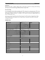
EXERCISE
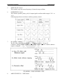
Resistors # 1
Band # 1
Band # 2
Multiplier
Tolerance
Total Resistance
Observed Resistance
Resistor # 2
Band # 1
Band # 2
Multiplier
Tolerance
Total Resistance
Observed Resistance
Resistor # 3
Band # 1
Band # 2
Multiplier
Tolerance
Total Resistance
Observed Resistance
Resistor # 4
Band # 1
Band # 2
Multiplier
Tolerance
Total Resistance
Observed Resistance
Color
Value
4
Engineering Workshop
Lab Session 01
NED University of Engineering & Technology – Department of Computer & Information Systems Engineering
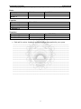
Diode
Diode #
Good / Bad
Diode # 1
Diode # 2
Capacitor
Printed Value
Capacitor # 1
Capacitor # 2
Capacitor # 3
Transistor
Transistor #
Type (NPN/PNP)
Transistor # 1
Transistor # 1
•
Find and list various shardware and their configuration attached to your system.
______________________________________________________________________
_______________________________________________________________________
_______________________________________________________________________
_______________________________________________________________________
_______________________________________________________________________
_______________________________________________________________________
_______________________________________________________________________
_______________________________________________________________________
_______________________________________________________________________
_______________________________________________________________________
_______________________________________________________________________
_______________________________________________________________________
_______________________________________________________________________
_______________________________________________________________________
_______________________________________________________________________
_______________________________________________________________________
5
Engineering Workshop
Lab Session 02
NED University of Engineering & Technology – Department of Computer & Information Systems Engineering
Lab Session 02
OBJECT
Familiarization and working with oscilloscope, function generator and 555 timer IC
THEORY
Until the 1990s, most oscilloscopes were purely ‘analog’ devices: an input voltage passed
through an amplifier and was applied to the deflection plates of a CRT to control the position of
the electron beam. The position of the beam was thus a direct analog of the input voltage. In the
past few years, analog scopes have been largely superseded by digital devices suchas the
TDS210 (although low-end analog scopes are still in common use for TV repair, etc.).Adigital
scope operates on the same principle as a digital music recorder. In a digital scope, the input
signal is sampled, digitized, and stored in memory. The digitized signal can then be displayed on
a computer screen. One of your first objectives will be to set up the scope to do some of the
things for which you may already have used simpler scopes. After that, you can learn about
multiple traces and triggering. In order to have something to look at on the scope, you can use
your breadboard’s built-in function generator, a device capable of producing square waves,
sinusoidal waves, and triangular waves of adjustable amplitude and frequency. But start by using
the built-in ‘calibrator’ signal provided by the scope on a metal contact labeled ‘probe comp’ (or
something similar), often located near the lower right-hand corner of the display screen.
6
Engineering Workshop
Lab Session 02
NED University of Engineering & Technology – Department of Computer & Information Systems Engineering
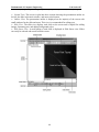
Display
Your oscilloscope user’s manual will explain the information displayed on the scope’s screen.
Record the various settings: timebase calibration, vertical scale factors, etc.
Vertical controls
There is a set of ‘vertical’ controls for each channel These adjust the sensitivity (volts per
vertical division on the screen) and offset (the vertical position on the screen that corresponds to
zero volts). The ‘CH 1 ’ and ‘CH 2 ’ menu buttons can be used to turn the display of each
channel on or off; they also select which control settings are programmed by the push-buttons
just to the right of the screen.
Horizontal sweep
To the right of the vertical controls are the horizontal controls .Normally, the scope displays
voltage on the vertical axis and time on the horizontal axis. The sec/div knob sets the sensitivity
of the horizontal axis, i.e. the interval of time per horizontal division on the screen. The position
knob moves the image horizontally on the screen.
Triggering
Triggering is probably the most complicated function performed by the scope. To create a stable
image of a repetitive waveform, the scope must ‘trigger’ its display at a particular voltage,
known as the trigger ‘threshold’. The display is synchronized whenever the input signal crosses
that voltage, so that many images of the signal occurring one after another can be superimposed
in the same place on the screen. The level knob sets the threshold voltage for triggering. You can
select whether triggering occurs when the threshold voltage is crossed from below(‘rising-edge’
triggering) or from above (‘falling-edge’ triggering) using the trigger menu (or, for some scope
models, using trigger control knobs and switches). You can also select the signal source for the
triggering circuitry to be channel 1, channel 2, an external trigger signal, or the 120 V AC power
line, and control various other triggering featuresas well.
Function Generator
Function generators are among the most important and versatile piece of equipment. In
electronics design and troubleshooting, the circuit under scrutiny often requires a controllable
signal to simulate its normal operation. The testing of physical system and transducers often
needs stable and reliable signals. The signal levels needed range from micro volts to tens of volts
or more.Modern DDS(Direct Digital Synthesis) function generator are able to prove a wide
variety of signals. Today`s basic units are capable of sine, square and triangle outputs from less
than 1 Hz to at least 1 MHz, with variable amplitude and adjustable DC offset. Many generators
include extra features, such as higher frequency capability, variable symmetry, frequency sweep,
AM / FM operation and gated burst mode. More advance model offer a variety of additional
waveforms and arbitrary waveforms generator can supply user can define periodic waveforms.
7
Engineering Workshop
Lab Session 02
NED University of Engineering & Technology – Department of Computer & Information Systems Engineering
Function generators are used where stable and repeatable stimulus signals are needed. Here are
some common use and users.
Research and development
Educational institutions
Electronics and electrical equipment repair businesses
Stimulus/response testing, frequency response characterization, and in-circuit signal
injection
Electronic hobbyists
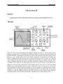
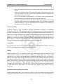
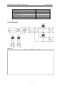
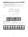
Function Generator FG-8002
FRONT PANEL
1.
POWER Switch
Pressing this push switch turns on power.
2.
POWER Lamp
LED lights up when power is on.
3.
Frequency Dial
This Variable potentiometer varies output frequency within the selected range with the
frequency range selector.
4.
SWEEP WIDTH / PULL ON Control
Pulling the knob selects internal sweep and rotating it controls sweep width. Rotate it
counter clockwise to get a minimum sweep width (1: 1) and rotate it clockwise to get a
maximum sweep width (100:1). To get a maximum sweep width, set the frequency dial
to minimum scale (below 0.2 scales). Pushing the knob selects external sweep, which is
implemented when external sweep voltage is applied to the VCF input connector.
8
Engineering Workshop
Lab Session 02
NED University of Engineering & Technology – Department of Computer & Information Systems Engineering
5.
SWEEP RATE Control
This controls weep rate (sweep frequency) of internal sweep oscillator.
6.
SYMMERTRY Control
This controls symmetry (duty cycle) of output signal waveform within range of 10: 1 to
1: 10.
Following figure hows waveforms varied by symmetry control.
7.
DC OFFSET Control
The DC offset control can provide up to + 10V open circuit, or + 5V into 50.
Clockwise rotation admixes positive voltage and counter clockwise rotation admixes
negative voltage.Ω.
8.
AMPLITUDE/PULL – 20dB Control
9
Engineering Workshop
Lab Session 02
NED University of Engineering & Technology – Department of Computer & Information Systems Engineering
Amplitude of output signal can be controlled by this knob. Maximum attenuation is more
than 20dB when the knob is rotated fully counter clockwise. Pulling this knob make
attenuation of 20dB, so the output signal can be attenuated by 40dB when this is pulled
and rotated fully counter clockwise.
9.
FREQUENCY RANGE Selector
Select one of the following seven ranges of oscillation frequency as desired.
10.
FUNCTION Selector
Push one of the three knobs to get a desired waveform out of sine wave, triangle wave
and square wave.
11.
VCF IN Connector
Frequency of output signal can be varied by applying voltage to this connector.
Application of voltage from 0 to + 10V provides frequency variation up to 100: 1.To
maximum variation, set the frequency dial to minimum scale. (below 0.2 scale)
12.
TTL – OUTPUT Connector
TTL – level square waves output from here.
13.
OUTPUT Connector
This is the main output connector for sine wave, triangle wave and square wave selected
with the FUNCTION Selector.
14.
Voltage Selector
Select rated voltage 110V or 220V according to the power line voltage to be applied to
the instrument.
15.
Power Cord
Connect to a power connector for supplying AC power.
16.
FUSE Holder
Fuse holder for AC power supply.Use a specified fuse for safety of the instrument.
Working with Function Generator
The purpose of this lab is familiarizing you with the basic functions of an oscilloscope and
function generators.
1. Setting Up The Oscilloscope and Function Generator
a. Turn on the oscilloscope with the button on the top. Attach a BNC to alligator cable
to the Channel 1 BNC input connector.
b. On the oscilloscope, set the following controls:
Channel 1 Volts / Division = 2 (The CH 1 menu button enables/disables the
channel, turn VOLTS/DIV knob).
Time / Division = 250µs (Turn SECONDS/DIV knob).
10
Engineering Workshop
Lab Session 02
NED University of Engineering & Technology – Department of Computer & Information Systems Engineering
Trigger Source = Channel 1 (Push TRIGGER MENU, select Channel 1 from the
Source menu).
Turn on the function generator. Attach another BNC to alligator cable to the output
connector (be careful not to attach it to the Sync (TTL) output). Attach the red
alligator clips from both cables together. Repeat with the black clips.
You will now configure the function generator to output a 10Vpp (peak-to-peak), 1
KHz sinusoidal wave.
Use the output arrows to select the sinusoidal wave pattern.
Highlight the Frequency option (FREQ under Display/Modify) and use the
MODIFIER and RANGE controls to set an output frequency of 1 KHz.
Highlight the Amplitude option (AMPL) and adjust Vp (peak voltage) for 5
volts.
You should now see a sinusoidal wave on the oscilloscope. If not, then ask a lab
assistant for help. The problem may be with some oscilloscope settings, some
"buried" function generator settings, or the physical connection.
Now, make sure the sinusoidal wave is vertically centred on your scope.
Press the Ch 1 menu button
Select the Ground option under the Coupling submenu.
The Channel 1 vertical position should be set to 0.00 divs (0.00V). If it is not,
adjust using the "Vertical Position" knob.
Since the cosine wave is the standard for sinusoidal wave patterns, adjust the
horizontal position of the wave so that the positive peak amplitude intercepts the
vertical axis. This can be adjusted using the "Horizontal Position".
c.
d.
e.
f.
g.
You should now have a stable cosine wave with an amplitude of 5 volts, a phase shift of 0
degrees, and a frequency of 1 KHz (see equation 1) display on the oscilloscope.
h. Using the cursors: The oscilloscopes are equipped with a set of horizontal and vertical
cursors to aid in obtaining measurements. You can use these to measure various
parameters like peak voltage, period, and frequency.
Measure the Peak-to-Peak amplitude of the waveform using the horizontal
cursors. To do this, press Cursor, and then select Voltage under the Type
submenu. Use the Vertical Position knobs to place the cursors at Vp and Vp. Under the delta submenu the peak to peak voltage will be
recorded. Repeat this process to measure the Peak Voltage.
Measure both the Period and Frequency of the waveform using the vertical
cursors. To do this, press Cursor, and then select Time under the Type
submenu. Use the Vertical Position knobs to again place the cursors. The
delta submenu displays both the period and frequency measurements.
11
Engineering Workshop
Lab Session 02
NED University of Engineering & Technology – Department of Computer & Information Systems Engineering
EXERCISES
1. Perform the same operation as demonstrated in the above exercise using a square wave and
write down you observations along with the waveform you observe on the system
________________________________________________________________
________________________________________________________________
________________________________________________________________
________________________________________________________________
________________________________________________________________
_______________________________________________________________
2. Measure the parameters for the following sinusoidal wave
v(t) = 5 cos(62832t + 0) volts
a. What is the frequency of the waveform in hertz? What is the period? What is Vp?
________________________________________________________________
________________________________________________________________
________________________________________________________________
________________________________________________________________
________________________________________________________________
_______________________________________________________________
b.
Adjust the function generator to output the waveform in equation 2. Start bringing up the
frequency from 1 KHz to the value you calculated in part a, and notice what happens to
the waveform displayed on the oscilloscope. Readjust the sec/div knob on the scope
until one or two periods take up most of the screen. What happens to the signal
displayed on the scope as the frequency from the function generator gets higher?
________________________________________________________________
________________________________________________________________
________________________________________________________________
________________________________________________________________
________________________________________________________________
________________________________________________________________
________________________________________________________________
________________________________________________________________
________________________________________________________________
_______________________________________________________________
12
Engineering Workshop
Lab Session 02
NED University of Engineering & Technology – Department of Computer & Information Systems Engineering
c.
With the cursors, measure Vp (peak) and Vpp (peak-to-peak) and record these values in
your lab book.
________________________________________________________________
________________________________________________________________
________________________________________________________________
________________________________________________________________
________________________________________________________________
________________________________________________________________
_______________________________________________________________
d.
With the cursors, measure the frequency of the waveform and record this value in your
lab book.
________________________________________________________________
________________________________________________________________
________________________________________________________________
________________________________________________________________
________________________________________________________________
________________________________________________________________
e.
Sketch the waveform as best as you can in your lab book. Be sure to fully label your plot
with axes, units and divisions.
13
Engineering Workshop
Lab Session 02
NED University of Engineering & Technology – Department of Computer & Information Systems Engineering
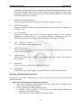
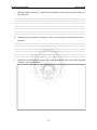
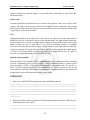
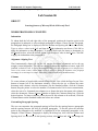
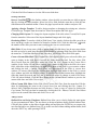
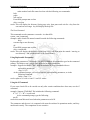
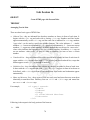
555 Timer IC
VCC 5V To +15V
R1
8
4
1
8
V (output)
R2
OUT
3
6
555
2
+
C
1
The 555 timer IC was first introduced around 1971 by the Signetic Corporation as the
SE555/NE555 and was called “the IC time machine”. This timer uses a maze of transistors,
diodes, and the resistors. The 555 comes in two packages, either the round metal can called the
“T Packager” or the more familiar 8-pin Div ‘V’ package. Inside the IC, are the resistors and 3
diodes depending on the manufacturer. The equivalent circuit providing the functions of control,
triggering, level sensing or comparison, discharge and power output. Some features of 555 IC
are: Supply voltage between 4.5 and 18 volts, supply 3 to 6 mA and rise and fall time of 100
msec. There are two modes to work. Monostable mode also known as one shot pulse generator
and the astable mode also called oscillator.
Relation of 555 Timer IC
The frequency, f which is generated is given by:
f =
1.44
(R1 + 2R2) C
OBSERVATIONS & CALCULATIONS
C
R1
R2
Calculated Frequency
1
2
3
14
Observed Frequency
Engineering Workshop
Lab Session 3
NED University of Engineering & Technology – Department of Computer & Information Systems Engineering
Lab Session 03
OBJECT
Constructing a full wave rectifier and half wave rectifier
THEORY
PN Junction Diode
If donor impurities are introduced into one side and acceptor impurities into the other side of a
single crystal of semiconductor ,a PN junction is formed. It is also called a diode.
Capacitance
A capacitor stores electric charge. It consists of a pair of plates set very close to each other but
separated by an insulator layer. When voltage is applied across a capacitor, it stores charge. If
batteries are now removed, the charge remains trapped in the capacitor. This trapped charge is
called capacitance. Capacitance is measured in Farad (F). capacitors are used in different values
like, pico farad (pF), Nano farad (nF), micro farad (µF), etc.
Micro farad, µF = 10-6 F
Nano farad, nF = 10-9 F
Pico farad, pF = 10-12 F
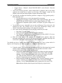
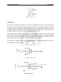
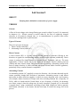
Rectifiers
Half-Wave Rectifier
The AC source produces a sinusoidal voltage. Assuming an ideal diode, the positive half cycle of
source voltage will forward-bias the diode. Since the switch is closed, the positive half cycle of
source voltage will appear across the load resistor. On the negative half cycle, the diode is
reverse-biased. In this case, the ideal diode will appear as an open switch, and no voltage appears
across the load resistor. Thus a unidirectional load current is produced i.e. it flows in only one
direction.
Full-Wave Rectifier
15
Engineering Workshop
Lab Session 3
NED University of Engineering & Technology – Department of Computer & Information Systems Engineering
The full-wave rectifier is equivalent to two half-wave rectifiers. Because of the centre tap in
transformer, each of these rectifiers has an input voltage equal to half the secondary voltage.
Diode D1 conducts on the positive half cycle, and diode D2 conducts on the negative half cycle.
The full-wave rectifier acts the same as two back-to-back half-wave rectifiers. During both half
cycles, the load voltage has the same polarity and the load current is in the same direction. The
circuit is called a full-wave rectifier because it has changed the A.C. input voltage to the
pulsating D.C. output voltage.
Figure 6.2: Half wave rectifier
igure6.2: Half wave rectifier
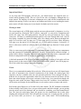
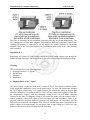
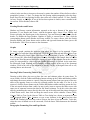
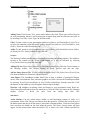
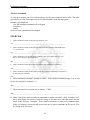
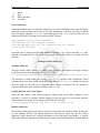
Bridge Rectifier
The bridge rectifier is similar to a full-wave rectifier because it produces a full-wave output
voltage. Diodes D1 and D3 conduct on the positive half cycle, and D3 and D4 conduct on negative
half cycle. As a result, the rectifed load current flows during both half cycles. During both half
cycles, the load voltage has the same polarity and the load current is in the same direction. The
circuit has changed the A.C. input voltgae to the plulsating D.C. output voltage. The advantage
of using Bridge Recitifer over Full-Wave Rectifieir is that the entire secondary voltage can be
used.
D1
D
220V
VinVout
D2
D3
Inductance
When current flow through a wire it creates a magnetic field. This field grows outward from the
center of the conductor as increases or collapse back into the center of the conductor. When
current starts flowing, a magnetic field is created which grows outwards from the center of the
conductor. When current decreases then the surrounding magnetic field starts to collapse back
into the conductor.
16
Engineering Workshop
Lab Session 3
NED University of Engineering & Technology – Department of Computer & Information Systems Engineering
Transformers
If two coils are wound close together so that they are ‘magnetically coupled’, then any changing
currents in one coil will induce changing currents in the other. If changing voltage is fed across
the input coil (the primary) then a similar changing voltage will appear across the output coil (the
secondary) There is no physical connection between input coil (primary coil) and output coil
(secondary coil) but these coil are connected through magnetic field.
If the primary and secondary winding have the same number of turns, then the output voltage
must be similar to the input. It means output voltage depends on the ratio of input and output
coils. If input coil has 100 number of turns and output coil has 10 number of turns, the ratio is
100/10, then output voltage must be ten time less than the input voltage.
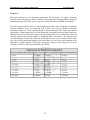
The transformer, which is shown is single output transformer. For multiple outputs we use centre
tape transformer as show in figure .
Transformer – Single output
Figure 4(b).7: Center tapped transformer
17
Engineering Workshop
Lab Session 3
NED University of Engineering & Technology – Department of Computer & Information Systems Engineering
RESULT
1. Draw a full wave output diagram.
18
Fundamentals of Computer Engineering
Lab Session 04
NED University of Engineering & Technology – Department of Computer & Information Systems Engineering
Lab Session 04
OBJECT
Designing Printed Circuit Boards.
THEORY
You've designed your circuit, perhaps even bread boarded a working prototype, and now it's
time to turn it into a nice Printed Circuit Board (PCB) design. For some designers, the PCB
design will be a natural and easy extension of the design process. But for many others the
process of designing and laying out a PCB can be a very daunting task. There are even very
experienced circuit designers who know very little about PCB design, and as such leave it up
to the "expert" specialist PCB designers. Many companies even have their own dedicated
PCB design departments. This is not surprising, considering that it often takes a great deal of
knowledge and talent to position hundreds of components and thousands of tracks into an
intricate (some say artistic) design that meets a whole host of physical and electrical
requirements. Proper PCB design is very often an integral part of a design. In many designs
(high speed digital, low level analog and RF to name a few) the PCB layout may make or
break the operation and electrical performance of the design. It must be remembered that
PCB traces have resistance, inductance, and capacitance, just like your circuit does.
The steps involved in PCB design can be listed here as under:
The Schematic
Before begin to lay out your PCB, you MUST have a complete and accurate schematic
diagram. A PCB design is a manufactured version of your schematic, so it is natural for the
PCB design to be influenced by the original schematic. If your schematic is neat, logical and
clearly laid out, then it really does make your PCB design job a lot easier. Good practice will
have signals flowing from inputs at the left to outputs on the right. With electrically important
sections drawn correctly, the way the designer would like them to be laid out on the PCB.
Like putting bypass capacitors next to the component they are meant for. Little notes on the
schematic that aid in the layout are very useful. For instance, “this pin requires a guard track
to signal ground”, makes it clear to the person laying out the board what precautions must be
taken. Even if it is you who designed the circuit and drew the schematic, notes not only
remind yourself when it comes to laying out the board, but they are useful for people
reviewing the design. Your schematic really should be drawn with the PCB design in mind.
The schematics for PCB Design can be drawn with the help of available design aid software.
The softwares that are mainly used for this purpose are orcad and workbench. You also learn
in preceding lab session, how to design circuits with the help of these softwares.
19
Fundamentals of Computer Engineering
Lab Session 04
NED University of Engineering & Technology – Department of Computer & Information Systems Engineering
Imperial and Metric
As any long time PCB designer will tell you, you should always use imperial units (i.e.
inches) when designing PCBs. This isn’t just for the sake of nostalgia, although that is a
major reason! The majority of electronic components were (and still are) manufactured with
imperial pin spacing. So this is no time to get stubborn and refuse to use anything but metric
units, metric will make laying out of your board a lot harder and a lot messier.
Working to Grids
The second major rule of PCB design, and the one most often missed by beginners, is to lay
out your board on a fixed grid. This is called a “snap grid”, as your cursor, components and
tracks will “snap” into fixed grid positions. Not just any size grid mind you, but a fairly
coarse one. 100 thou is a standard placement grid for very basic through hole work, with 50
thou being a standard for general tracking work, like running tracks between through hole
pads. For even finer work you may use a 25 thou snap grid or even lower. Many designers
will argue over the merits of a 20 thou grid v/s a 25 thou grid for instance. In practice, 25
thou is often more useful as it allows you to go exactly half way between 50 thou spaced
pads.
Why is a coarse snap grid so important? It’s important because it will keep your components
neat and symmetrical; aesthetically pleasing if you may. It’s not just for aesthetics though - it
makes future editing, dragging, movement and alignment of your tracks, components and
blocks of components easier as your layout grows in size and complexity.
A bad and amateurish PCB design is instantly recognizable, as many of the tracks will not
line up exactly in the center of pads. Little bits of tracks will be “tacked” on to fill in gaps etc.
This is the result of not using a snap grid effectively.
Tracks
There is no recommended standard for track sizes. What size track you use will depend upon
(in order of importance) the electrical requirements of the design, the routing space and
clearance you have available, and your own personal preference. Every design will have a
different set of electrical requirements which can vary between tracks on the board. All but
basic non-critical designs will require a mixture of track sizes. As a general rule though, the
bigger the track width, the better. Bigger tracks have lower DC resistance, lower inductance,
can be easier and cheaper for the manufacturer to etch, and are easier to inspect and rework.
Real world typical figures are 10/10 and 8/8 for basic boards. The IPC standard recommends
4 thou as being a lower limit. Once you get to 6thou tracks and below though, you are getting
into the serious end of the business and you should be consulting your board manufacturer
first. The lower the track/space figure, the greater care the manufacturer has to take when
aligning and etching the board. They will pass this cost onto you, so make sure that you don’t
go any lower than you need to. As a guide, with “home made” PCB manufacturing
20
Fundamentals of Computer Engineering
Lab Session 04
NED University of Engineering & Technology – Department of Computer & Information Systems Engineering
processeslike laser printed transparencies and pre-coated photo resist boards, it is possible to
easily get 10/10 and even 8/8 spacing.
Changing your track from large to small and then back to large again is known as “necking”,
or “necking down”. This is often required when you have to go between IC or component
pads. This allows you to have nice big low impedance tracks, but still have the flexibility to
route between tight spots.
The thickness of the copper on the PCB is nominally specified in ounces per square foot, with
1oz copper being the most common. You can order other thicknesses like 0.5oz, 2oz and 4oz.
The thicker copper layers are useful for high current, high reliability designs.
Pads
Pad sizes, shapes and dimensions will depend not only upon the component you are using,
but also the manufacturing process used to assemble the board, among other things. There is
an important parameter known as the pad/hole ratio. This is the ratio of the pad size to the
hole size. Each manufacturer will have his own minimum specification for this. As a simple
rule of thumb, the pad should be at least 1.8 times the diameter of the hole, or at least 0.5mm
21
Fundamentals of Computer Engineering
Lab Session 04
NED University of Engineering & Technology – Department of Computer & Information Systems Engineering
larger. This is to allow for alignment tolerances on the drill and the artwork on top and
bottom layers. This ratio gets more important the smaller the pad and hole become, and is
particularly relevant to vias.
There are some common practices used when it comes to generic component pads. Pads for
leaded components like resistors, capacitors and diodes should be round, with around 70 thou
diameter being common. Dual In Line (DIL) components like IC’s are better suited with oval
shaped pads (60 thou high by 90-100 thou wide is common). Pin 1 of the chip should always
be a different pad shape, usually rectangular, and with the same dimensions as the other pins.
Most surface mount components use rectangular pads, although surface mount SO package
ICs should use oval pads. Again, with pin 1 being rectangular. Other components that rely on
pin numbering, like connectors and SIP resistor packs, should also follow the “rectangular
pin 1” rule.Octagonal pads are seldom used, and should generally be avoided. As a general
rule, use circular or oval pads unless you need to use rectangular.
Vias
Vias connect the tracks from one side of your board to another, by way of a hole in your
board. On all but cheap home made and low end commercial prototypes, vias are made with
electrically plated holes, called Plated Through Holes (PTH). Plated through holes allow
electrical connection between different layers on your board.
Holes in vias are usually a fair bit smaller than component pads, with 0.5-0.7mm being
typical.Using a via to connect two layers is commonly called “stitching”, as you are
effectively electrically stitching both layers together, like threading a needle back and forth
through material.
Polygons
“Polygons” are available on many PCB packages. A polygon automatically fills in (or
“floods”) a desired area with copper, which “flows” around other pads and tracks. They are
very useful for laying down ground planes. Make sure you place polygons after you have
placed all of your tacks and pads.Polygon can either be “solid” fills of copper, or “hatched”
copper tracks in a crisscross fashion. Solid fills are preferred, hatched fills are basically a
thing of the past.
22
Fundamentals of Computer Engineering
Lab Session 04
NED University of Engineering & Technology – Department of Computer & Information Systems Engineering
Clearances
Electrical clearances are an important requirement for all boards. Too tight a clearance
between tracks and pads may lead to “hairline” shorts and other etching problems during the
manufacturing process. These can be very hard to fault find once your board is assembled.
For 240V mains on PCB’s there are various legal requirements, and you’ll need to consult the
relevant standards if you are doing this sort of work. As a rule of thumb, an absolute
minimum of 8mm (315 thou) spacing should be allowed between 240V tracks and isolated
signal tracks. Good design practice would dictate that you would have much larger clearances
than this anyway.For non-mains voltages, the IPC standard has a set of tables that define the
clearance required for various voltages. A simplified table is shown here. The clearance will
vary depending on whether the tracks are on an internal layers or the external surface. They
also vary with the operational height of the board above sea level, due to the thinning of the
atmosphere at high altitudes. Conformal coating also improves these figures for a given
clearance, and this is often used on military spec PCBs.
23
Fundamentals of Computer Engineering
Lab Session 04
NED University of Engineering & Technology – Department of Computer & Information Systems Engineering
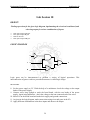
Demonstrating PCB
You have already implemented the circuit mentioned below using breadboard / veroboard in
previous lab session. We are going to implement the very same circuit with PCB in this lab
session.
VCC 5V To +15V
R1
8
4
2
8
V (output)
3
OUT
R2
6
2
555
+
C
1
Patterning (etching)
The vast majority of printed circuit boards are made by bonding a layer of copper over the
entire substrate, sometimes on both sides, (creating a "blank PCB") then removing unwanted
copper after applying a temporary mask (e.g. by etching), leaving only the desired copper
traces. A few PCBs are made by adding traces to the bare substrate (or a substrate with a very
thin layer of copper) usually by a complex process of multiple electroplating steps. The PCB
manufacturing method primarily depends on whether it is for production volume or
sample/prototype quantities.
Circuit Schematics Imprint
The print of the circuit depends on the requirement which can be categorized as follow:
• Commercial
o silk screen printing–the main commercial method
o Photographic methods–used when fine line widths are required
•
Non Commercial
o Laser-printed resist: Laser-print onto paper
24
Fundamentals of Computer Engineering
Lab Session 04
NED University of Engineering & Technology – Department of Computer & Information Systems Engineering
o Print onto transparent film and use as photo mask along with photo-sensitized
boards.
o Laser resist ablation: Spray black paint onto copper clad laminate, place into
CNC laser plotter. The laser raster-scans the PCB and ablates (vaporizes) the
paint where no resist is wanted.
o Use a CNC-mill with a spade-shaped (i.e. 45-degree) cutter or miniature endmill to route away the undesired copper, leaving only the traces.
o By using a liquid proof marker that draws tracks on the copper sheet, leaving
only the region required for conducting purpose and afterwords performing
chemical etching to convert remaining portion as insulator. (The method we
are going to use in this lab session)
Chemical etching
Chemical etching is done with ferric chloride, ammonium persulfate, or sometimes
hydrochloric acid. For PTH (plated-through holes), additional steps of electroless deposition
are done after the holes are drilled, then copper is electroplated to build up the thickness, the
boards are screened, and plated with tin/lead. The tin/lead becomes the resist leaving the bare
copper to be etched away.The simplest method, used for small scale production and often by
hobbyists, is immersion etching, in which the board is submerged in etching solution such as
ferric chloride. Compared with methods used for mass production, the etching time is long.
Heat and agitation can be applied to the bath to speed the etching rate.
Lamination
Some PCBs have trace layers inside the PCB and are called multi-layer PCBs. These are
formed by bonding together separately etched thin boards.
Drilling
Holes through a PCB are typically drilled with small-diameter drill bits made of solid
coated tungsten carbide. Coated tungsten carbide is recommended since many board
materials are very abrasive and drilling must be high RPM and high feed to be cost effective.
Drill bits must also remain sharp to not mar or tear the traces. Drilling with high-speed-steel
is simply not feasible since the drill bits will dull quickly and thus tear the copper and ruin the
boards. The drilling is performed by automated drilling machines with placement controlled
by a drill tape or drill file. These computer-generated files are also called numerically
controlled drill (NCD) files or "Excellon files". The drill file describes the location and size
of each drilled hole. These holes are often filled with annular rings (hollow rivets) to
create vias.
Exposed conductor plating and coating
PCBs are plated with solder, tin, or gold over nickel as a resist for etching away the unneeded
underlying copper.After PCBs are etched and then rinsed with water, the soldermask is
25
Fundamentals of Computer Engineering
Lab Session 04
NED University of Engineering & Technology – Department of Computer & Information Systems Engineering
applied, and then any exposed copper is coated with solder, nickel/gold, or some other anticorrosion coating.
Solder resist
Areas that should not be soldered may be covered with a polymer solder resist (solder mask)
coating. The solder resist prevents solder from bridging between conductors and creating
short circuits. Solder resist also provides some protection from the environment. Solder resist
is typically 20–30 micrometres thick.
Test
Unpopulated boards may be subjected to a bare-board test where each circuit connection (as
defined in a netlist) is verified as correct on the finished board. For high-volume production,
a Bed of nails tester, a fixture or a Rigid needle adapter is used to make contact with copper
lands or holes on one or both sides of the board to facilitate testing. A computer
will instruct the electrical test unit to apply a small voltage to each contact point on the bedof-nails as required, and verify that such voltage appears at other appropriate contact points.
A "short" on a board would be a connection where there should not be one; an "open" is
between two points that should be connected but are not.
Printed circuit assembly
After the printed circuit board (PCB) is completed, electronic components must be attached
to form a functional printed circuit assembly, or PCA (sometimes called a "printed circuit
board assembly" PCBA). In through-hole construction, component leads are inserted in
holes. In surface-mount construction, the components are placed on pads or lands on the
outer surfaces of the PCB. In both kinds of construction, component leads are electrically and
mechanically fixed to the board with a molten metal solder.
EXERCISES
1. How you can differ PCB designing from other assembling projects?
________________________________________________________________
________________________________________________________________
________________________________________________________________
________________________________________________________________
________________________________________________________________
__________
2. What sort of unit system is preffered in PCB designing, Imperial or Metric? What do you
understand by the term “thou”?
________________________________________________________________
________________________________________________________________
26
Fundamentals of Computer Engineering
Lab Session 04
NED University of Engineering & Technology – Department of Computer & Information Systems Engineering
________________________________________________________________
________________________________________________________________
________________________________________________________________
__________
3. Discuss briefly the concept of “necking”
________________________________________________________________
________________________________________________________________
________________________________________________________________
________________________________________________________________
________________________________________________________________
4. What are Vias? How they help connecting two different layers? Is there any difference
between vias and pads?
________________________________________________________________
________________________________________________________________
________________________________________________________________
________________________________________________________________
________________________________________________________________
__________
5.In this exercise you have to mention each and every step taken by you to fabricate the PCB
for the timer circuit given in this labs session Did you follow all the necessary steps
mentioned in this lab session for the fabrication? If not then mention why?
________________________________________________________________
________________________________________________________________
________________________________________________________________
________________________________________________________________
________________________________________________________________
________________________________________________________________
________________________________________________________________
________________________________________________________________
________________________________________________________________
________________________________________________________________
________________________________________________________________
________________________________________________________________
________________________________________________________________
________________________________________________________________
________________________________________________________________
27
Fundamentals of Computer Engineering
Lab Session 04
NED University of Engineering & Technology – Department of Computer & Information Systems Engineering
________________________________________________________________
________________________________________________________________
________________________________________________________________
________________________________________________________________
________________________________________________________________
________________________________________________________________
________________________________________________________________
________________________________________________________________
________________________________________________________________
________________________________________________________________
________________________________________________________________
________________________________________________________________
________________________________________________________________
________________________________________________________________
________________________________________________________________
28
Fundamentals of Computer Engineering
Lab Session 05
NED University of Engineering & Technology – Department of Computer & Information Systems Engineering
Lab Session 5
OBJECT
Studying basics behind the construction of a power supply.
THEORY
Current
A flow of electric charge or the charge flowing per second is called Current(I). It is measured
in Amperes (A) – Electric current is carried either by the flow of negatively charged
electrons, or of positively charged ions, or, in semiconductors, by positive holes where
electrons are missing from a crystal structure.
Types of Current
There are two types of current.
1. Direct Current (called DC)
2. Alternating Current (called AC)
Direct Current
A direct current (DC) is a steady electric current (stream of electrons) flowing in one
direction, as opposed to an alternating current, which reverses direction periodically. Direct
current is produced by simple batteries in cassette players, flashlights, and toys. The main
applications of direct current are in the fields of electronics, traction (battery-powered
vehicles and some electric trains), and electrochemical processing. Alternating current in the
form of mains electricity is often converted into direct current inside electrical appliances,
particularly if they contain electronic components.
Alternating Current
An alternating current (AC) regularly reverses its direction – the electrons that make up the
current constantly change their direction of movement. Alternating current is used almost
universally in mains electricity supplies, in which it reverses direction with a set frequency
(for example, mains electricity in Europe and Asia, including Pakistan has a frequency of
50 Hz, while in Canada and the United States, it has a frequency of 60 Hz). Its advantage
over direct current is that the voltage may be easily increased (“stepped up”) or decreased
(“stepped down)” using a transformer according to need. High voltages are used to generate
and transmit electricity to our homes, because this helps to reduce the energy lost in the
process.
29
Fundamentals of Computer Engineering
Lab Session 05
NED University of Engineering & Technology – Department of Computer & Information Systems Engineering
Capacitor Input Filter
The capacitor input filter produces a D.C. output voltage equal to the peak value of the
rectified voltage. This type of filter is the most widely used in power supplies. Other type of
filter is choke input filter which is not used due to its high cost and weight.
Initially, the capacitor is uncharged. During the first quarter cycle the diode is forward biased.
Since it ideally acts like a closed switch the capacitor charges and its voltage equals the
source voltage at each instant of the first quarter cycle. The charging continues until the input
reaches its maximum value. At this point, the capacitor voltage equals the peak value of the
rectified voltage.
After the input voltage reaches the peak, it starts to decrease. As soon as the input voltage is
less then the peak value, the diode turns off. In this case, it acts like the open switch. During
the remaining cycle, the capacitor stays fully charged and the diode remains open. This is
why output voltage is constant and equal to the peak value.
Transformers
A transformer is two coils of wire (called the primary coil and the secondary coil) wrapped
around a piece of iron. It makes AC voltages larger or smaller, depending on how the coils
are arranged.
Step-Up and Step-Down Transformers
A transformer with more windings in the secondary coil than in the primary increases voltage
and is called a step-up transformer. The reverse arrangement, a step-down transformer,
decreases voltage.
Mathematically,
Vs /Vp = Ns / Np
Voltage in secondary coil / voltage in primary coil = number of coils in secondary coil /
number of coils in primary coil.
A transformer works because the alternating voltage carried in one coil induces an alternating
voltage in the other coil. This is called mutual inductance.
30
Fundamentals of Computer Engineering
Lab Session 05
NED University of Engineering & Technology – Department of Computer & Information Systems Engineering
The coils, or windings, are not connected electrically, but they are linked magnetically. The
two windings have at least some magnetic flux (magnetic field lines) common to both. If one
winding (the primary) is connected to an AC supply, the current produces an alternating
magnetic flux in the core which induces an electromotive force (emf) in the other winding
(the secondary).
Regulating ICs
Regulating ICs consist of Zener Diodes, which have fixed output voltage even though the
current through it changes. The Zener Diode is got to be reverse biased for normal operation.
Working
The circuit functions in the following steps:
1. Stepping Down of A.C. Signal
2. Rectification
3. Filtration
4. Regulation
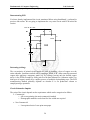
1. Stepping Down of A.C. Signal
The power supply is connected with an A.C. source of 220 V. The current is allowed to flow
to the step-down transformer via the on-off switch and a 2 A fuse. The transformer changes
the 220 V signal at input into a 14 V signal at output. The transformer works on the principal
of mutual inductance. According to which, if two coils are wound close together so that they
are ‘magnetically coupled’, then any changing currents in one coil will induce changing
currents in the other. If changing voltage is fed across the input coil (the primary) then a
similar changing voltage will appear across the output coil (the secondary). There is no
physical connection between input coil (primary coil) and output coil (secondary coil) but
these coils are connected with magnetic field. The coil with the most turns corresponds to the
higher voltage in the transformer. To step down from a high voltage to a lower one, the
primary coil must have more windings than the secondary.
31
Fundamentals of Computer Engineering
Lab Session 05
NED University of Engineering & Technology – Department of Computer & Information Systems Engineering
2. Rectification
The current is then allowed to pass through the bridge-rectifier (made by using four 1N4001
diodes). The diode bridge rectifies the A.C. signal into a pulsating D.C. form. During the
positive half cycle diodes D1 and D3 conducts the current in the positive direction while
during the negative half cycle the gets reverse biased and hence stops the flow of current. On
the other hand diodes D2 and D4 conducts during the negative half cycle. This pulsating D.C.
is then allowed to pass through the capacitor for filtration.
3. Filtration
The pulsating D.C. is filtered by using a 2200 µF-35V capacitor (to make it more manageable
for the regulator) and thus we get a pure D.C. During the first quarter cycle the rising voltage
charges the capacitor and when the voltage starts to reduce the capacitor starts to discharge
and thus a stabilized D.C. voltage is obtained.
Although the D.C. obtained is almost a pure one, but it may contain some ripples. Thus one
more capacitor (of 0.1 µF) is used. This capacitor further filters the D.C. voltage and thus a
pure D.C. is obtained. This pure D.C. is then fed to the regulating ICs of Model 7812 and
7805.
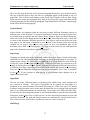
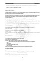
4. Regulation
The regulators have fixed outputs i.e. output of Regulator 7812 is +12 V whereas that of
Regulator 7805 is +5 V. The output obtained from these regulating ICs may contain some
ripples therefore, these outputs are further filtered by using capacitors of 100 µF - 25 V and
100 µF - 16 V respectively.
EXERCISES
Construct a power supply with two D.C. outputs i.e. 12 Volts and 5 Volts.
Components Required
Component
Transformer - Input 220 V
Output 14 V, 2A
Diode - Model: IN4001
Capacitor - 2200 µF, 35 V
Capacitor - 0.1 µF/104 pF
Capacitor - 100 µF, 25 V
Capacitor - 100 µF, 16 V
Regulator - 7812 (for 12 V output)
Regulator - 7815 (for 5 V output)
Quantity
1
4
1
1
1
1
1
1
32
Fundamentals of Computer Engineering
Lab Session 05
NED University of Engineering & Technology – Department of Computer & Information Systems Engineering
Bread Board
Banana Jacks
Fuse Holder
Fuse 220 V, 2 A
On – Off Switch with Indicator
Plug, Cord & Casing
1
2 Sets (2 Black & 2 Red)
1
1
1
1
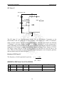
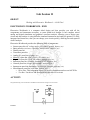
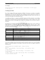
Circuit Diagram
D2
D1
D3
D4
Figure 4.5: Circuit diagram of a regulating IC
RESULT
Lab Session 06
33
Section Two:
Introduction to MS Office and
Operating System
34
Fundamentals of Computer Engineering
Lab Session 06
NED University of Engineering & Technology – Department of Computer & Information Systems Engineering
Lab Session 06
OBJECT
Learning features of Microsoft Word & Microsoft Excel
WORD PROCESSING CONCEPTS
Indentation
To indent both the left and right sides of the paragraph, position the insertion point in the
paragraph to be indented, or select multiple paragraphs to indent; Choose Format, Paragraph,
the Paragraph dialog box is displayed; click the Indents and Spacing tab if it is not selected;
Type or select a value in the Left and then the Right indentation text boxes. Click OK to
apply the indentation to the paragraph(s). To modify block style for letters or documents, in
the Special list box, select the desired option; type or select a value in the By box. Click OK
to apply the indentation to the paragraph(s).
Alignment: Aligning Text
Word automatically aligns text on the left margin (horizontal alignment) and to the top
margin (vertical alignment). The user can choose to change the alignment to center, right, full
justified, or back to left. To change horizontal alignment, select the paragraph(s) to be changed; Press
Ctrl+L (Left), Ctrl+E (Center), Ctrl+R (Right), or Ctrl+J (Justify) to change the alignment of the paragraph
accordingly (or use the Align Left, Center, Align Right, or Justify buttons on the Standard toolbar).
Columns
To create columns of equal width, switch to Page Layout View (click the Page Layout View
button at bottom left of the document window); Select the text (or to format the entire
document with columns, select the document); On the Standard toolbar, click the Columns
button; Drag the pointer to select the number of columns needed. Or for more customization,
select the text to be formatted into columns (or to format the entire document with columns,
select the document); Choose Format, Columns to display the Columns dialog box; Click the
desired options. To remove columns, select the text for the columns to be removed; Click the
Columns button on the Standard toolbar and select one column.
Customizing Paragraph Spacing
The user can customize the paragraph spacing in Word for the spacing between paragraphs
and the spacing between the lines in specified paragraphs. To do this, place the insertion
point in the paragraph to be modified, or highlight all of the contiguous paragraphs to be
changed; Choose Format, Paragraph to display the dialog box, then click the Indents and
Spacing tab if it is not active; In the Spacing section, select Before and After and change the
35
Fundamentals of Computer Engineering
Lab Session 06
NED University of Engineering & Technology – Department of Computer & Information Systems Engineering
value(s) in the text box to increase or decrease by points the number of lines before or after a
paragraph (6 points = 1 line); To change the line spacing within paragraphs, select the dropdown arrow for the Line Spacing list box, then select one of these options: 1.5 lines, Double,
At least, Exactly, or Multiple; If one of the last three options is chosen, enter a number in the
At text box. When finished, choose OK.
Creating Headers and Footers
Headers and footers contain information repeated at the top or bottom of the pages in a
document. To set Header and Footer, with the document open, choose View, Header and
Footer to display the Header pane in the document; Type and format the information for the
header; To include the Page Number, Number of Pages, or current Date or Time, click the
corresponding button on the Header and Footer toolbar; To create a footer, click the Switch
Between Header and Footer button on the toolbar and type and format the footer just as did
for the header. Click Close to return to the document.
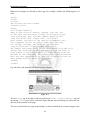
Graphs
To insert a graph, position the insertion point where the chart is to be appeared. Choose
Insert, Object to open the Object dialog box. Click the Create New tab and in the Object Type
box, select Microsoft Graph Chart. Float Over Text is the default. If prefer, click Display as
Icon. Choose OK; Microsoft Graph opens showing a datasheet with sample data in it. This
overlays the Word document which now displays a graph of that sample data at the insertion
point. It is surrounded by a box with eight handles indicating it is selected. At the same time,
the Microsoft Graph Standard and Formatting toolbars appear at the top of the document
window; Click in the cells of the datasheet or use the Tab key to navigate from cell to cell,
entering data to suit the needs
Drawing Tables/Converting Table to Text
Drawing a table allows the user to place the rows and columns where he wants them. To
create a table, click the Tables and Borders button to bring up the Tables and Borders toolbar
and change the mouse pointer to a pencil; Drag the mouse pointer from one corner of the new
table to the opposite corner to create the rectangle outline for the table; If a line is to be
removed, click the Eraser button on the Tables and Borders toolbar and drag across the line.
If the user needs the data from a table, he may (rarely) want to convert the table to text with
some sort of separator between the data for the former columns. To do this, select the entire
table by positioning the mouse directly above the top of the table until the pointer changes to
a black down arrow, then click and drag the mouse across all the columns. Choose Table,
Convert Table to Text; In the Convert Table to Text dialog box, choose to separate the text
with Paragraph Marks, Tabs, Commas, or type a new character in the Other text box; then
choose OK. Similarly the user may want to convert the lines of text into a table. To do this,
select the rows of tabbed text to be converted; Click the Insert Table button on the Standard
toolbar.
Paragraphs: Formatting Line and Page Breaks
36
Fundamentals of Computer Engineering
Lab Session 06
NED University of Engineering & Technology – Department of Computer & Information Systems Engineering
The Line and Page Breaks tab on the Format Paragraphs dialog box gives detailed control.
The user would not want to have one line of a paragraph appear on the bottom or top of a
page alone. This is Widow and Orphan control. Keep Lines Together will not allow a page
break anywhere within the paragraph. Keep with Next will prevent a page break between the
selected paragraph and the following paragraph. Page Break Before will insert a manual page
break before the selected paragraph.
Sections Breaks
Section breaks are important when the user need to apply different formatting choices to
different parts of the document. To insert Section Breaks, position the insertion point where
the section break is required, and then choose Insert, Break to display the Break dialog box;
Select one of the Section Break options listed in the table following these steps; Choose OK
to return to the document. Different options are: Next Page-to start section at the top of the
next page in the document; Continuous-to start section at the insertion point (for varying
columns on one page); Even Page-to start section on next even-numbered page in the
document (most often a left-facing page); Odd Page-to start section on next odd-numbered
page in the document (most often a right-facing page).
Page Setup
Changing the default page layout formatting enables the user to choose whether the headers
and footers are the same throughout the document, or change from odd page to even page. To
change layout, choose File, Page Setup to display the Page Setup dialog box, then select the
Layout tab; In the Section Start drop-down list, select from where the new sections are to be
started; In the Headers and Footers section, click one of the options: Different Odd and Even
or Different First Page, depending on the needs for the headers and footers in the document;
Select the Vertical Alignment drop-down arrow to choose between Top, Center, or Justified;
In the Apply To box, indicate to what portion of the document these changes are to be
applied, then choose OK.
Hyperlinks
The user can create a link that jumps to a document, also called a page, on his computer and
on a network or intranet. Two types of hyperlinks can be created. one that jumps to a
bookmark in the same document and another that jumps to a URL.First type is for named
locations. Named locations can be in the same document the user is working with (an internal
link), or in a different document (an external link). Second type is for URLs and other links.
For this click the Insert Hyperlink button on the Standard toolbar to open the Insert Hyperlink
dialog box; In the Link to File or URL text box, click the upper Browse button to locate and
select the document. The path and document name are automatically entered in the Link to
File or URL text box; choose OK to confirm the choice or Cancel to negate it.
Mail Merge
37
Fundamentals of Computer Engineering
Lab Session 06
NED University of Engineering & Technology – Department of Computer & Information Systems Engineering
If the user is sending many documents, mail merge can save lots of time. The user can design
a form that prints multiple labels on a page similar to the way he designs a form letter.
•
Creating Main Document - A main document is a letter, envelope, or other document that
has text that the user wants to appear on every merge, and codes that will be replaced with
entries from a data source of names and addresses.
To create the main document, open the existing document to be used, or a new blank
document window. Then choose Tools, Mail Merge to display the Mail Merge Helper;
Click the Create button under Step 1 Main document, then select Form Letters; Word will
give a choice to use the Active Window, which is the document window that is open
behind the dialog box. Or, start a New Main Document, which will open a new blank
document window; Word takes back to the Mail Merge Helper dialog box, which now
displays the type of merge and the name and path of the document under the Main
Document step; Now choose Get Data under Step 2.
•
Opening a Existing Data Source - The existing data source could be a Word document, an
Excel document, an Access database or query, a dBASE file, or even a FoxPro file, as
well as many others. For this, in Get Data under Step 2, while creating the main
document, on the dialog box, choose Open Data Source to display the Open Data Source
dialog box; Word can read many different data source formats. Choose the drop-down
arrow on the Files of Type list to select the file type for the data source; Navigate in the
Look In list to find the drive and folder where the data source file is stored. Select the file
and choose Open, or if available, click the MS Query button if a non-Word database is to
be selected; When prompted that Word found no merge fields in the main document,
choose the Edit Main Document button to insert merge fields into the main document.
•
Creating Data Source - If the user does not have a data source that contains list of names
and addresses for the merge document, one can be created using the Mail Merge Helper.
Address information from Outlook and Schedule+ can also be used.
To do this, in Get Data under Step 2, while creating the main document, on the dialog
box, choose Create Data Source to display the Create Data Source dialog box; Scroll
through the list of fields in the Field Names in Header Row list box to see commonly
used field names provided by Word; Edit the list of field names using the list following
these steps and when finished, choose OK; Word displays the Save As dialog box. In the
File Name box, enter a name for the data source document and choose Save; Word
displays a decision box; choose Edit Data Source to enter information into the data source
file just created, or choose Edit Main Document to insert merge fields into the main
document.
Field names can also be changed through various options. Select the field name which is
not required from the list, then choose the Remove Field Name button; To add a field
name that isn't listed, type the name in the Field Name text box, then choose Add Field
Name; To change the sequence of field names, select a field name in the Field Names in
38
Fundamentals of Computer Engineering
Lab Session 06
NED University of Engineering & Technology – Department of Computer & Information Systems Engineering
Header Row list box, then click the up-arrow or down-arrow buttons. The top-to-bottom
order of the fields is the order the fields will be in for data entry in the data source.
•
Entering Data - After the user has created a data source, he will need to enter information
into the source and edit existing information. If the data source is created in an application
other than Word, follow the procedures for entering and editing in the source application.
If, on the other hand, the source has been created in Word using the Mail Merge Helper,
follow the instructions given below.
•
Inserting Fields - Once the user has attached a data source for the mail merge, he is ready
to insert merge fields in the main document. Merge fields are the variable information
that changes for each document. For this, if the main document is not opened with the
Mail Merge toolbar displayed, click the Mail Merge Helper button on the toolbar. Click
Edit under Step 1 Main Document, and then select the main document from the displayed
list; Position the insertion point where a merge field is to be appeared. Click the Insert
Merge Field button on the Mail Merge toolbar, and then select the field from the list
presented; Type any text or punctuation that is needed in the document and continue
inserting merge fields where necessary.
Microsoft Excel
Entering Formulas
Formulas enable the user to perform calculations by using values in the worksheet. Arithmetic operators that can
be used in formulas include + for addition, - for subtraction, * for multiplication, / for division, % for
percentage, and ^ for exponentiation. For example : =a1+b1 adds the contents of a1 and b1 in the cell where
the formula is typed.To reference cells in other Worksheets, select the cell where the formula is to be appeared ,
and type an equal sign (=) to start the formula; Click the sheet tab containing the cell to be referenced in the
formula; Select the cell or range to be referred to. The complete reference appears in the formula bar; Finish the
rest of the formula; then press Enter to complete the formula.
Excel also provides functions like SUM, AVERAGE, etc.
- SUM: Adds all the numbers in a range of cells.
Syntax: =SUM(number1, number2, …..)
AVERAGE: Returns the average (arithmetic mean) of the arguments.
Syntax: =AVERAGE(number1, number2, …..)
- COUNT: Counts the number of cells that contain numbers and numbers within the list of
arguments.
Syntax: =COUNT(value1, value2, …..)
- COUNTA: Counts the number of cells that are not empty and the values within the list of
arguments.
Syntax: =COUNTA(value1, value2, …..)
- PRODUCT: Multiplies all the numbers given as arguments and returns the product.
Syntax: =PRODUCT(number1, number2, …..)
- SUMIF: Adds the cells specified by a given criteria.
Syntax: SUMIF(range, criteria, sum_range)
39
Fundamentals of Computer Engineering
Lab Session 06
NED University of Engineering & Technology – Department of Computer & Information Systems Engineering
Where ‘Range’ is the range of cells to be evaluated according to the given criteria.
‘Criteria’ is the criteria in the form of a number, expression, or text that defines which
cells will be added. ‘Sum_range’ are the actual cells to sum. The cells in sum_range are
summed only if their corresponding cells in range match the criteria. If sum_range
is omitted, the cells in range are summed.
For example: Suppose B1:B4 contain the values 100, 200, 300, and 400 respectively.
C1:C4 contains 1, 4, 6, and 2 respectively. Now the expression
SUMIF(B1:B4,">275",C1:C4) will add 6 and 2 as there corresponding values in cells B3
and B4 are greater than 275. Hence the result will be 8. If sum_range argument is omitted
then the result becomes 700.
-
FACT: gives factorial of a number
Syntax: FACT(num)
Large: returns kth largest value
Syntax: Large (Array, K)
SMALL: returns kth smallest value
Syntax: small(array, k)
Ceiling: returns nearest kth value integer
Formulas: Absolute, Relative, and Mixed Cell References
When a cell contains a formula with references to other cells, several methods can be used to
handle those references.Excel normally uses relative references for cell addresses in a
formula, unless specified otherwise. When relative references are used, the cell references in
a formula automatically adjust after the formula is copied to another cell or range. If cell B10
contains the formula =SUM(B3:B9), for example, and user copies this formula from cell B10
to cell C10, the new formula in cell C10 automatically adjusts to read =SUM(C3:C9).
Creating a Text String
At times, the user may need to create a formula that joins the contents of two cells. Excel
refers to this action as concatenation. For example: If a worksheet includes first names in
column B3 and last names in column C3, the user can enter a formula in a third column that
joins the first name with the last name:
=B3&" "&C3
where ampersand (&) is the concatenation operator and (" ") simply
indicates a space between the two text strings.
Displaying Formula Instead of Results
From anywhere in the worksheet, choose Tools, Options; then click the View tab; Select the
Formulas check box; then click OK. To display the results again, choose Tools, Options; then
clear the Formulas check box on the View tab. Press Ctrl+ ' (the grave accent, usually located
on the same key as the tilde character) to toggle between viewing results and formulas.
40
Fundamentals of Computer Engineering
Lab Session 06
NED University of Engineering & Technology – Department of Computer & Information Systems Engineering
AutoCalculate
Select the range to be summed. The AutoCalculate button in the status bar automatically
displays the sum of the selected range (or right click the AutoCalculate button to see more
functions); Right-click the AutoCalculate button in the status bar; From the pop-up menu that
appears, select the function to be used, such as Average or Count. The result of the function
selected appears in the status bar.
Logical Functions
The logical functions enables the user to add decision-making and logical tests to the
worksheets. The IF statement is useful for testing conditions and making decisions based on a
cell's contents. The AND and OR functions can test multiple criteria or test conditions for use
in IF functions. The following examples show the use:
•
•
•
•
=AND(D15,G23<30)
result is TRUE only when D15 is not zero and G23 is less than
30
=IF(AND(D17>10,D17<30),"Valid","Invalid")
returns Valid if the contents of cell
D17 is greater than 10 and less than 30; otherwise the formula returns Invalid
=IF(NOT(OR(D17=10,D17=30)),"Not 10 or 30","Contains 10 or 30")
tests whether
cell D17 contains the result 10 or 30 and produces the message Not 10 or 30 when the cell
does not contain either of those results; otherwise, the formula result is Contains 10 or 30
=IF(OR(D17=10,D17=30),"Contains 10 or 30","Not 10 or 30") tests whether cell D17
contains the result 10 or 30 and produces the message Contains 10 or 30 when it does;
otherwise, the formula produces the message Not 10 or 30
Math and Trigonometric Functions
Like logical functions, math and trigonometric functions can also be used in the Worksheets.
Trigonometric functions use angles measured in radians. Following are some examples:
• =ABS(A10) returns 18 when cell A10 contains -18
• =ACOS(0.5) returns 1.047198 (radians)
• =DEGREES(0.5) returns 28.64789 (degrees)
• =LOG(12,3) returns 2.26186
• =ROUND(102.927,2) returns 102.93
Statistical Functions
Similarly, statistical functions can als0 be used in the Worksheets. For example:
•
•
•
=COUNTIF(B1:B4,">100") returns 1 if the range B1:B4 contains the numbers 57, 102,
84, and 98
=MEDIAN(1,4,2,6,9) returns 4
=MEDIAN(1,4,2,6,9,10) returns 5 (average of the two middle values, 4 and 6)
41
Fundamentals of Computer Engineering
Lab Session 06
NED University of Engineering & Technology – Department of Computer & Information Systems Engineering
EXERCISE
•
Write a report of not more than two pages, on different types of computer systems namely
microcomputers, minicomputers, mainframes, super computers. The report should be
properly formatted with appropriate indentations, and font styles with single line spacing
and the specified alignment : 1 cm from left, 1 cm from top. You may use additional
styles like drop cap and columns. Include your name and roll number in the header field.
Also, the total market in 1985 for the products and services of the top 100 companies in
the computing industry is given below as percentages. Present this information in
graphical form.
Microcomputers - 10.18% ; Minicomputers - 11.18% ; Mainframes - 6.8% ;
Data communications - 7.46% ; Peripherals - 27.23% ; Software - 7.63% ;
Services - 5.72% ; Maintenance - 11.56% ;
Other - 2.19%
•
Create a word document, using mail merge wizard, which produces individual
information reports for a list of students in the form of a table, including their first name,
last name, father’s name, home address, phone number, email addresses, and home page
address as hyperlinks (if any). Enter few sample records. Table should be properly
formatted. Remember to include your name and roll number in the header field. Get a
printout to be attached here, of the page that contains only field name and not any records.
Also attach 1 sample report containing actual data.
•
Draw the sine ( sin θ ) and cosine ( cos θ ) wave on a single graph and format the graph
accordingly. Take θ from 0° to 360° with the interval of 15°. Also Compare the values of
sin and cos and tell at which angle these values are equal.
•
Create a magic square puzzle as per given example below, the sum of all the numbers in a
row must be equal, simultaneously the sum of all the numbers in a column must be equal,
and the sum of diagonal numbers should also be equal:
24
12
3
9
24
5
8
11
24
7
13
4
24
24
24
24
24
WELL DONE!!!
Take the input from the user in all the squares. For a user all the squares will be blank
initially and the box given below will contain the text “KEEP TRYING” unless the user
enters all correct entries. If user solve the puzzle correctly then a message “WELL DONE”
appears below. Format your work accordingly.
42
Fundamentals of Computer Engineering
Lab Session 07
NED University of Engineering & Technology – Department of Computer & Information Systems Engineering
Lab Session 07
OBJECT
Familiarization with the environment of Microsoft Power Point.
USING POWER POINT
A user can communicate information better and more easily with a PowerPoint presentation. A presentation is a
series of slides that a user creates by using PowerPoint. The more important the message, the clearer the
presentation should be. Also for larger audience, the message must be easy to grasp.
The facilities PowerPoint provides are discussed below:
Creating a New Power Point Presentation
Presentation Type: Open Power Point and you will be prompted by a dialog box with
different choices. These choices are explained below. If Power Point is already open or this
box does not appear, select File|New from the menu bar.
• AutoContent Wizard: The AutoContent Wizard provides templates and ideas for a variety
of presentation types. Page through the wizard by clicking the Next button on the bottom of
each page after making necessary choices.
• Design Template: Power Point provides many templates with different backgrounds and
text formatting to begin your presentation. Preview each design by highlighting the template
name on the list. Press OK after you have chosen the design.
• Blank Presentation: Select Blank Presentation to build the presentation from scratch with
no preset graphics or formatting.
• Open an Existing Presentation: Select this option to open a Power Point presentation that
already exists. Select the folder the file is located in from the Look in: drop-down menu and
highlight the file on the list. Click Open to open the presentation.
AutoLayout: After selecting the presentation type, you will be prompted to choose the layout
of the new slide. These layouts include bulleted lists, graphs, and/or images. Click on each
thumbnail image and a description will be printed in the message box. Highlight the layout
you want and click OK.
Screen Layout Views
Power Point gives you four screen layouts for constructing your presentation in addition to
the Slide Show. You can select the page view by clicking the buttons at the bottom of the
page.
43
Fundamentals of Computer Engineering
Lab Session 07
NED University of Engineering & Technology – Department of Computer & Information Systems Engineering
• Normal View: This screen is split into three sections showing the presentation outline on
the left, the slide in the main window, and notes at the bottom.
• Outline View: The presentation outline is displayed on the majority of the screen with
small windows for the slide and notes. This view is recommended for editing text.
• Slide View: The slide view displays each slide on the screen and is helpful for adding
images, formatting text, and adding background styles.
• Slide Sorter View: A small image of each slide is displayed in Slide Sorter view. Slides
can easily be ordered and sorted from this screen.
44
Engineering Workshop
Lab Session 07
NED University of Engineering & Technology – Department of Computer & Information Systems Engineering
Click the Slide Show button to view the full-screen slide show.
Working With Slides
Insert a New Slide
: In the Outline window, select the slide you want the new slide to appear
after by clicking the slide's number. Select Insert|New Slide from the menu bar or click the new
slide button on the standard toolbar. Choose the page layout from the window and press OK.
Applying a Design Template: To add a design template or changing the existing one, selection
Format|Design Template from the menu bar. Select the template and click Apply.
Changing Slide Layouts: To change the layout template of the slide select Format|Slide Layout
from the menu bar. Select one of the layout thumbnail images and click Apply.
Reordering Slides: To reorder a slide in Slide Sorter View, simply click on the slide you wish to
move and drag it to the new location. In Normal or Outline View, click the slide icon
beside
the number of the slide you want to move and drag the icon to a new location.
Hide Slides: If you do not want a slide to appear during the slide show, but do not want to delete
the slide as it may be used later, the slide can be hidden by selecting Slide Show|Hide Slide from
the menu bar. To add the slide back to the slide show, select Slide Show|Hide Slide again.
Create a Custom Slide Show: The Custom Slide Show feature allows you to select the slides you
want to display in the slide show if not all the slides should be used. For this, select Slide
Show|Custom from the Slide Show menu bar; Click the New... button in the Custom Shows
window; In the Define Custom Show window, type a name for the slide in the Slide show name
field; Add slides to the custom show by highlighting them in the Slides in presentation window
and clicking the Add >> button. Those slides will then appear in the Slides in custom show
window; To remove slides from the custom show, highlight their names in the Slides in custom
show window and click the Remove button; To reorder slides in the custom show, highlight the
slide that should be moved and click the up and down arrows to change its order in the show;
Click OK when finished; Click the Show button on the Custom Shows window to preview the
custom slide show and click Close to exit.
Edit a Custom Slide Show: Select Slide Show|Custom Slide Show from the menu bar; Edit the
show by highlighting the name in the Custom shows box and clicking the Edit... button; To
delete a show, highlight the name and click Remove; Create a copy of a show by clicking the
Copy button. The copy can then be renamed by clicking the Edit... button; Click the Show button
to preview the custom slide show and click Close to exit.
Adding Contents
Bulleted Lists on Design Templates: Bulleted lists allow you to clearly display the main points
of your presentation on slides. The text boxes on design templates already include bulleted lists.
Click the place holder on the slide to begin adding text and press the ENTER key to return to the
next line and add a new bulleted item. To go to the next line without adding another bullet, hold
down the SHIFT key while pressing ENTER.
45
Engineering Workshop
Lab Session 07
NED University of Engineering & Technology – Department of Computer & Information Systems Engineering
Adding Notes: From Normal View, notes can be added to the slide. These notes will not be seen
on your presentation, but they can be printed out on paper along with the slide the notes refer to
by selecting Print What: Notes Pages on the Print menu.
Video: To add a video to your presentation select Insert|Movies and Sounds|Movie from File or
to insert an animation from Microsoft's gallery choose Insert|Movies and Sounds|Movie from
Gallery. Select the video file and click OK.
Audio: To add sound to your presentation select Insert|Movies and Sounds|Sound from Gallery
or Sound from File. Select a sound file and click OK.
Graphics
The Drawing Toolbar provides many commands for creating and editing graphics. The toolbar is
located at the bottom of the Power Point screen or it can be activated by selecting
View|Toolbars|Drawing from the menu bar.
Adding Clip Art: Select Insert|Picture|Clip Art from the menu bar or click the Picture button on
the Drawing toolbar. Use various options to insert, preview and edit the clips.
Add An Image from a File: To add a photo or graphic from a file, Select Insert|Picture|From
File from the menu bar. Choose the clip and insert it.
Auto Shapes: The AutoShapes toolbar allows you to draw a number of geometrical shapes,
arrows, flow chart elements, stars, and other graphics on a slide. Activate the AutoShapes toolbar
by selecting Insert|Picture|AutoShapes or View|Toolbars|AutoShapes from the menu bar. Click
the buttons on the toolbar to view the options for drawing each shape.
WordArt: Add headlines in striking colors and shapes to your presentation using Word Art.
Select Insert|Picture|WordArt from the menu bar or click the Word Art button on the Drawing
toolbar. Choose a Word Art style from the listing and click OK.
Slide Effects
Action Buttons: Use the action button toolbar to add functioning buttons to slides in a
presentation. Select Slide Show|Action Buttons from the menu bar. Click the bar across the top of
the button menu and drag it off the menu so it becomes a floating toolbar. Click one of the button
faces and draw the button on the slide using the mouse. The Action Settings menu will then
appear. Set the actions under either the Mouse Click or Mouse Over tabs. Actions specified for
46
Engineering Workshop
Lab Session 07
NED University of Engineering & Technology – Department of Computer & Information Systems Engineering
Mouse Click will execute when the button is clicked on the slide while actions for Mouse Over
will occur when the mouse pointer hovers over the button. Select an action for the button by
choosing a Hyperlink to destination. If you want a sound to be played when the button is clicked,
check the Play sound box and choose a sound from the drop-down menu. Click OK when
finished. The button on the slide can be resized using the white box handles and the depth of the
button can be changed by dragging the yellow diamond.
Slide Animation
Several animations for slide objects are available through the drop-down menus on the menu bar.
First, select the text box or graphic that will be animated. Select Slide Show|Preset Animation
and choose from one of the options. To select a different animation or turn the animation off,
select the appropriate choice from the same menu.
Slide Transitions: Select Slide Show|Slide Transition from the menu bar. From the Effect
section, choose a transition from the drop-down menu and notice the preview after the transition
is selected. Select a speed for the transition as well. Under Advance, check "On mouse click" for
the slide transition to occur by clicking the mouse or using keystrokes or check "Automatically
after" and a number of seconds if the transition should occur automatically. Select a Sound if
necessary and check the Loop until next sound if it should keep repeating until the next sound is
played. Click Apply to All if the transition effects should be added to every slide or Apply if the
effects should be added only to the current slide.
Slide Show Options
Select Tools|Options and click the View tab to choose from several more slide show options.
Popup menu on right mouse click - Check this box if you want to be able to access the shortcut menu during a
presentation.
Show popup menu button - Check this box to activate the menu button that appears in the bottom, left corner of
the screen during a presentation.
End with black slide - Insert a blank, black slide to the end of the presentation.
Master Slides
Slide Master: Change the style of all slides in the presentation by changing the properties on the
Slide Master. Each Design Template has its own Slide Master that can be altered. If you create
slides from scratch, a consistent style can be added to the presentation by formatting the Slide
Master. Select View|Master|Slide Master from the menu bar. Format the master slide just as you
would format a regular slide by formatting text, formatting lists, adding background patterns and
effects, and setting footers. Click the Close button on the Master toolbar to quit editing the
master slide and return to the presentation.
Headers and Footers: Add the date and time, slide numbers, and other footer text to the master
slide from the Header and Footer window. Select View|Header and Footer... from the menu bar.
Check the Date and time box to add this feature to the slide. Select Update automatically to
always display the current date and time or click Fixed and enter a date that will not change in
the text field provided. Check the Slide number box to add this feature to the slides. Click the
Footer box and add other text to the footer area of the slide. Check the Don't show on title slide
box to hide these features on the title slide of the presentation. Click the Notes and Handouts tab
47
Engineering Workshop
Lab Session 07
NED University of Engineering & Technology – Department of Computer & Information Systems Engineering
to make the same changes to notes and handouts pages. Click Apply to All to add the changes to
every slide or Apply to add only to the current slide.
Slide Numbers: To add the slide numbers in a fixed position on the slide, use the Header and
Footer window detailed above. The slide number can otherwise be added anywhere on the slide
by placing the cursor where the slide number should appear and selecting Insert|Slide Number
from the menu bar. The text of the slide number can the formatting just as regular text style is
changed.
Date and Time: A date and/or time can also be added using the Header and Footer window or
anywhere else on the slide. Place the cursor where the date and time should appear on the slide
and select Insert|Date and Time from the menu bar. Select a format from the Available formats
box and click Update automatically if this feature should always be updated to reflect the current
date and time. Click OK to finish.
Presentation Basics
Begin the slide show by clicking the Slide Show button on the bottom of the screen.
Move to the next slide by pressing the SPACE BAR, ENTER, PAGE DOWN, or right arrow keys or by clicking the
left mouse button.
Go back to the previous slide by pressing BACKSPACE, PAGE UP, or the left arrow key.
To end the slideshow before it is complete press ESC on the keyboard.
A pen tool is available for drawing on the screen with the mouse. Press CTRL+P or click the right mouse button at
any time and a popup window will appear. Choose Pen and the pointer will change to a pen that allows you to
draw freehand on the screen using the mouse. Press the E key to erase all pen strokes. Press CTRL+A to disable
the pen feature and revert the pen back to a pointer arrow.
If you would like to use the pen to draw on a blank screen during a presentation, press the B or W keys, or select
Screen/Black Screen from the popup menu and the screen will turn black. Press B or W again or choose Next from
the popup menu to return to the presentation when you are finished drawing.
To hide the pointer and button from the screen press the A key.
Be sure to preview the slide show using a projector if one will be used during the presentation. Words or graphics
that are close to the edge of the screen may be cut off by the projector.
EXERCISE
•
Create a Power Point presentation for the report prepared in laboratory session 4, of not more than 4 slides. Add
appropriate animation effects and clip arts where necessary. Attach the printed output here
48
Engineering Workshop
Lab Session 08
NED University of Engineering & Technology – Department of Computer & Information Systems Engineering
Lab Session 08
OBJECT
Familiarization with DOS environment and its important commands.
WORKING WITH DOS
Understanding DOS
DOS, the acronym for Disk Operating System, is an operating system with a command-line interface used on
personal computers. It provides a set of commands that enables the users to access or manipulate information on
their disks, as well as simply interact with their computer.
Dos
DriveCommands
(Root
Directory)
Sub
Directory
Command
Extension
File Name
DOS commands are of two types namely internal commands and external commands.
• Internal commands are those which are built into command.com.
• External commands are those that must be located from a file loaded by command.com before it can be
executed.
A brief description of important DOS commands is given below:
Changing drive
Type drive letter of the drive to which you want to switch to, on the command prompt followed
by ‘:’.
example: c:>a:
result: a:>
This will change the current drive from C to A.
49
Engineering Workshop
Lab Session 08
NED University of Engineering & Technology – Department of Computer & Information Systems Engineering
Wild Cards
DOS recognizes two wild cards:
• The asterisk (*) represents one or more characters that a group of files has in common.
• The question mark (?) represents a single character that a group of files has in common.
Working with Directories
•
dir to view the contents of a directory
syntax: drive:>dir
example: c:>dir This will list all the files and subdirectories on drive C.
Use wild cards to display selected lists. For example:
- drive:>dir *.*
displays all files and subdirectories on the drive
- drive>:dir ?????.com displays all files having names up to five characters
and extension ‘com’
dir command can be modified using these wild cards and other switches as follows so
that only one screen of selected information is displayed at a time.
dir /p lists the directory contents page wise.
dir/w lists the directory contents in a wider format, only file names and extensions.
dir/w/p lists the directory contents in a wider format, page wise.
•
cd to change from one directory to another
syntax: drive:>cd drive:\ path
example: c:>cd dos This will change the current directory from the root directory to
DOS directory on drive C.
result: c:\maria>
•
md to create a new directory
syntax: drive:>md drive:\ path\ dirname
example: c:>md neduet This will create a new directory named ‘neduet’ on drive C.
•
cd.. to switch back one level up in the directory structure
syntax: drive:\ dir:>cd..
example: c:\dos>cd..
This will switch back to root directory of drive C.
result: c:\>
•
rd
to delete a directory
syntax: drive:\ dir:>rd drive:\ path\ dirname
example: c:\>rd neduet. This will switch back to root directory of drive C.
Working with Files
•
•
copy
to copy a file from one directory or drive to another
syntax: drive:> copy drive:\source path\filename
drive:\destination path\ filename
example: c:\>copy c:\neduet\cfile.exe c:\windows
This will copy cfile.exe from neduet directory to windows directory.
ren
to rename a file
syntax: drive:>ren drive:\path\old filename drive:\path\new filename
example: c:\>ren cfile.exe edit.exe
This will rename cfile.exe to edit.exe.
50
Engineering Workshop
Lab Session 08
NED University of Engineering & Technology – Department of Computer & Information Systems Engineering
•
del
to delete a file
syntax: drive:>del drive:\path\filename
example: c:\>del cfile.exe This will delete cfile.exe.
Wild cards can be used with any of the above commands to work with group of files.
•
type
to view a file on the screen.
syntax: drive:>type drive:\path\filename
example: c:\>type file.txt This will list cfile.exe.
Files longer than one screen scroll off the top. To avoid this, use ctrl+s keystroke or
more, following the command.
example: c:\>type file.txt |more
•
fc
to compare files in either ASCII or binary mode
syntax: drive:>fc drive:\path\filename1 drive:\path\new filename2
example: c:\>fc a:\command.com c:\DOS\drivers\command.com
This will compare the two files.
Disk Management
•
format
to format a disk
syntax: drive:>format drive:
example: c:\>format a: This will format floppy disk in drive A.
•
diskcopy
to copy all contents of one disk to another. It is a floppy only command
syntax: drive:>diskcopy drive1: drive2:
example: c:\>diskcopy a: b:
This will copy everything from disk in drive A to disk in drive B.
•
chkdsk
to get a report on statistics of the disk
syntax: drive:>chkdsk drive:
example: c:\>chkdsk c: This will generate a report on statistics of drive C.
•
diskcomp
•
•
to verify that two disks are identical by comparing each track of one disk
to another, sector by sector. It’s a floppy only command
syntax: drive:>diskcomp drive1: drive:
example: c:\>diskcomp a: b:
This will compare the contents of disk in drive A with that of disk in drive B.
syntax: drive:>ver
example: c:\>ver This will display the current version of DOS on your system.
path
to set command search path
syntax: drive:>path drive:\pathname1
Use ‘;’ to specify more than one paths)
example: c:\>path c:\neduet;c:\float
This will tell Dos to search for programs in neduet directory, then in float directory.
doskey
to recall previously generated DOS commands
syntax: drive:>doskey
example: c:\>doskey This will install doskey.
Use UP and DOWN ARROWS to recall commands; ESC clears command line; F7
51
Engineering Workshop
Lab Session 08
NED University of Engineering & Technology – Department of Computer & Information Systems Engineering
displays command history; ALT+F7 clears command history; F8 searches command
history; F9 selects a command by number.
MAKING BATCH FILES
A batch program of a batch file is a text file that contains a series of commands that DOS carries
out when its name is typed at the command prompt.
AUTOEXEC.BAT file is an example of such files. It is a special batch program that runs every
time you start your computer. It starts necessary programs and does settings at the startup.
To make a batch file
• Open a new text file in an editor (DOS editor, ‘EDIT’ can be used, type edit at the
command prompt to see this editor).
• Type DOS commands, which are to be included in the batch program in this text file. Each
command is typed on a different line.
• Save the file with suitable name provided that its extension is bat. For example, mybatch.bat
The Echo Command
This command directs DOS whether or not to display the commands in a batch file.
syntax: echo on/off
An alternate is to insert @ sign before the command.
example: @ dir
This if included in the batch file, will prevent dir command from displaying on the command
prompt.
The Call Command
This command calls one batch program form another.
syntax: call [drive:][path]filename
example: make a batch file named one.bat with command dir/p
make another batch file named two.bat with the following two commands:
help
call one.bat
From DOS prompt rum two.bat
drive:>two.bat
result: This will display the directory listing, page wise and then the help file
The Pause Command
This command suspends processing of a batch program and displays the message:
Press any key to continue...
syntax: pause
example: make a batch file named one.bat with command dir/p
52
Engineering Workshop
Lab Session 08
NED University of Engineering & Technology – Department of Computer & Information Systems Engineering
make another batch file named two.bat with the following two commands:
help
pause
call one.bat
From DOS prompt rum two.bat
drive:>two.bat
result: This will display the directory listing page wise, then pause and wait for a key from the
user and on receiving a key will display the help file.
The Rem Command
This command records comments <remarks> in a batch file
syntax: rem [comments]
example: make a batch file named remark.bat with the following commands:
dir/p
rem moving to root directory
cd\
From DOS prompt rum two.bat
drive:>remark.bat
result: This will display the directory listing page wise, will then print the remark “moving to
root directory” and will then move to the root directory.
Using Replaceable Parameters
Replaceable parameters (%0 through %9) are placeholders for parameters typed at the command
prompt. This helps to use a single batch program for many parameters.
example: Suppose the BAKIT.BAT program includes the copy command with two
replaceable parameters:
copy %1 %2
At the command prompt, you can type the two corresponding parameters, as in the
following command:
bakit c:\com\*.* a:
result: replaces %1 with c:\com\*.* and %2 with a:.
Using the If Command
If you want a batch file to be carried out only after certain conditions have been met, use the if
command.
example: Suppose STAR.BAT file includes the following command:
if “%1” = = “W” c:\word\word
At the command prompt, type the following:
star W
result: this starts Microsoft word when the parameter used is W.
The parameter and the text it is compared with must be enclosed in quotations marks, and they
must match exactly. The comparison is case sensitive.
53
Engineering Workshop
Lab Session 08
NED University of Engineering & Technology – Department of Computer & Information Systems Engineering
The Goto Command
To switch to another part of a batch program, use the goto command and a label. The label
(preceded by a colon) must appear on its own line elsewhere in the batch program.
example: goto skipdown
echo this comment command will be skipped
:skipdown
doskey
result: the echo command will be skipped.
EXERCISE
1.
Write command to display all files having extension ‘com’
Ans: ______________________________________________________________________
2.
Write command to display all files having names up to five characters with middle letter
‘a’, e.g. smart.com
Ans: ______________________________________________________________________
3.
Write command to copy all files having extension ‘com’ from ‘neduet’ directory on C
drive to ‘fruit’ directory on the same drive.
Ans: ______________________________________________________________________
4.
Write command to delete all files having extension ‘old’ and starting with letter ‘p’.
Ans: ______________________________________________________________________
5.
Write command to display all file names on the disk in drive A and having an extension of
no more than two characters.
Ans:_______________________________________________________________________
6. Write command to change C prompt to ‘hello:’. Write another command using ‘$’ to switch
back to the standard C prompt (C:\>).
Ans:_______________________________________________________________________
7. Write command to set system date to January 1, 2002.
Ans:_______________________________________________________________________
8. Make a batch file which includes the commands to make a directory called ‘examples’ on C
drive, then display the directory and file listing of the same drive and then move into the
newly made directory ‘examples’. Print remarks/comments on what each command does
before its respective execution and do not echo any of actual commands on the screen. Give
the listing of the file below.
54
Engineering Workshop
Lab Session 08
NED University of Engineering & Technology – Department of Computer & Information Systems Engineering
Ans: _______________________________
_______________________________
_______________________________
_______________________________
_______________________________
_______________________________
_______________________________
_______________________________
_______________________________
_______________________________
________________________________
________________________________
________________________________
________________________________
________________________________
________________________________
________________________________
________________________________
________________________________
________________________________
55
Section Three:
Computer Hardware
Components Required
Bread board, 5 V - power supply, multimeter, logic probe (or LEDs with
resistors), wires, following ICs and their datasheets:
•
•
•
•
•
7408 quad 2 input AND gate
7432 quad 2 input OR gate
7404 hex inverter
7400 quad 2 input NAND gate
7402 quad 2 input NOR gate
56
Engineering Workshop
Lab Session 09
NED University of Engineering & Technology – Department of Computer & Information Systems Engineering
Lab Session 09
OBJECT
Experimenting with the AND, OR, NAND, NOR and NOT integrated circuits.
THEORY
Logic Gates
Logic gates are the fundamental building blocks of digital systems. These devices are able to
make decisions, in the sense that they produce one output level when some combinations of input
levels are present and a different output when other combinations are applied; hence given the
name Logic Gates.
The two levels produced by digital circuitry are referred to variously as HIGH and LOW, TRUE
and FALSE, ON and OFF, or simply 1 and 0.
There are only three basic gates: AND, OR and NOT. The other gates are merely combinations
of these basic gates.
1. The AND Gate – An AND gate’s output is 1 if and only if all its inputs are 1. If A and B are
two inputs to an AND gate then output, F of the gate is given as:
F = A.B
2. The OR Gate - An OR gate’s output is 1 if at least one of its input is 1. If A and B are two
inputs to an OR gate then output, F of the gate is given as:
F = A+B
3. The NOT Gate (Inverter) – Its output is 1 when its input is 0 and its output is 0 when the
input is 1; i.e. it complements a digital variable. If A is the input to a NOT gate then output, F
of the gate is given as:
F = A
4. The NAND Gate – Its output is 1 if at least one of its input is 0. This gate performs the same
logic as an AND gate followed by an inverter. If A and B are two inputs to a NAND gate
then output, F of the gate is given as:
F = A.B
5. The NOR Gate - The output of a NOR gate is 1 if and only if all its inputs are 0. This gate
performs the same logic function as an OR gate followed by an inverter. If A and B are two
inputs to a NAND gate then output, F of the gate is given as: F = A+B
All the above gates have one output and two or more inputs except the NOT gate, which has only
one input.
57
Engineering Workshop
Lab Session 09
NED University of Engineering & Technology – Department of Computer & Information Systems Engineering
PROCEDURE
1. Set the power supply to 5V. With the help of a multimeter check the voltage at the output
knobs of the power supply.
2. Connect wires, long enough to reach the bread board, with the two knobs of the power
supply. Again using multimeter, check the voltage at the non-connected end of the wires.
3. Insert the 7408 quad 2 input AND gate IC on to the bread board and make supply and ground
connections by joining 5V wire to pin # 14 and 0V wire to pin # 7.
4. Consult IC’s internal connection diagram for input and output pins of the first AND gate.
Connect input pins to logic 0 (0V) and observe the output using LED or logic probe.
5. Try different combinations of logic levels at the two inputs. Again observe the output.
6. Repeat the last two steps for all other gates of the same IC. Record the observations.
7. Repeat this procedure for all other ICs.
Exercise
1. Read the details of each of the IC discussed from the respective datasheets and
verify the expected outputs.
58
Engineering Workshop
Lab Session 10
NED University of Engineering & Technology – Department of Computer & Information Systems Engineering
Lab Session 10
OBJECT
Finding expression for the given logic diagram, implementing the circuit on bread board, and
observing output for various combinations of inputs.
•
•
•
•
7408 quad 2 input AND gate
7432 quad 2 input OR gate
7404 hex inverter
7402 quad 2 input NOR gate
LOGIC DIAGRAM
o
F
A
lo
B
Logic gates can be interconnected to perform a variety of logical operations. This
interconnection of gates to achieve prescribed outcomes is called logic design.
PROCEDURE
8. Set the power supply to 5V. With the help of a multimeter check the voltage at the output
knobs of the power supply.
9. Connect wires, long enough to reach the bread board, with the two knobs of the power
supply. Again using millimeter , check the voltage at the non-connected end of the wires.
10. Insert ICs on the bread board and make their supply and ground connections.
11. As given in the logic diagram, make connections using wires and gates in the ICs.
12. Apply different combinations at the three inputs and observe the output.
59
Engineering Workshop
Lab Session 10
NED University of Engineering & Technology – Department of Computer & Information Systems Engineering
OBSERVATIONS
Logic expression for the given logic diagram: ______________________________________
A
0
0
0
0
1
1
1
1
B
0
0
1
1
0
0
1
1
C
0
1
0
1
0
1
0
1
Expected Output
Observed Output
Exercise:
For the following exercises, develop a Boolean expression that satisfy the given
scenario . Give meaningful variable names to inputs/outputs.
1. An automatic vehicle system which ensures that the the belt buzzer starts its
beep as soon as the key is inserted.
2.A UPS who displays an alert signal as soon as the battery gets charged fully.
3. Real world example to be assigned by the instructor.
60
Engineering Workshop
Lab Session 11
NED University of Engineering & Technology – Department of Computer & Information Systems Engineering
Lab Session 11
OBJECT
Working with Electronics Workbench – A CAD Tool.
ELECTRONICS WORKBENCH - EWB
Electronics Workbench is a computer aided design tool that provides you with all the
components and instruments necessary to create board-level designs. It has complete mixed
analog and digital simulation and graphical waveform analysis, allowing you to design your
circuit and then analyze it using different simulated instruments and analysis options. It is fully
integrated and interactive, thus you can change your circuits quickly, allowing fast and repeated
what-if analysis.
Electronics Workbench provides the following kind of components:
• Sources parts bin (AC voltage source, Vcc source, ground, battery, etc)
• Basic parts bin (resistors, capacitors, transformers, switches, etc)
• Diodes parts bin
• Transistors parts bin
• Analog ICs parts bin (op-amps, etc)
• Mixed ICs parts bin (ADCs, DACs, 555 timers, etc)
• Digital ICs parts bin (AND, OR, adders, multiplexers, etc)
• Indicators parts bin (voltmeter, ammeter, probe, displays, etc)
• Controls parts bin (voltage differentiator, multiplier, etc)
• Instruments parts bin (multimeter, oscilloscope, function generator, etc)
• Miscellaneous parts bin (write data, textbox, etc)
o Write data: This component allows you to save simulation results as an ASCII file.
o Text Box: Use this to add descriptive text anywhere in a circuit.
ACTIVITY
Design the following circuit in Electronics Workbench and measure the voltage across each resistor.
R2 : 5Ω
R1: 1Ω
R3 : 4Ω
24V
Procedure
61
Engineering Workshop
Lab Session 11
NED University of Engineering & Technology – Department of Computer & Information Systems Engineering
1.
2.
3.
4.
5.
6.
7.
From Basic parts bin, Drag and drop a resistor on the design area.
Right click this component and select Component Properties. Click the Value tab, set the resistance to 1 ohm.
Repeat these two steps to place R2 and R3 resistors and a 24V battery.
Connect the terminals of these components as required. Use additional connectors form the basic parts bin if you want to connect two wires
at a single node.
Now add two voltmeters from indicators parts bin to the circuit. Connect one voltmeter across R1 and the other across R2 or R3.
Label the circuit properly using text boxes found in the miscellaneous parts bin.
Run the circuit using the Activate Simulation switch. Record the voltages across different terminals that appear in the voltmeters.
EWB Circuit
Observations
Resistor
Observed Reading
Calculated Reading
R1
R2
R3
PRACTICE PROBLEM
For the circuit given in this session, measure the current through each resistor for the following
values:
Resistor
Ω
Observed
Reading
Calculated
Reading
Resistor
Ω
Observed
Reading
Calculated
Reading
Resistor
Ω
R1=1
R1=2
R1=2
R2=5
R2=2
R2=4
R3=4
R3=2
R3=4
62
Observed
Reading
Calculated
Reading
Section Three:
Visual Basic Programming
Components Required:
USB to TTL Converter.
63
Engineering Workshop
Lab Session 12
NED University of Engineering & Technology – Department of Computer & Information Systems Engineering
Lab Session 12
OBJECT
Designing a Simple Stop Watch using VB Timer Control
THEORY
In this lab session you will be introduce with different tools (command buttons, label, text boxes
etc) available in the tool box in Visual Studio 2010 in VB.NET and learn how to change their
properties.The Timer control allows you to perform a task at a specified interval or to wait for a
specified length of time.
STEPS
To create a Stopwatch, you will create a new project as previously explained. Once the project is
created and you have selected a form for the form design, you will want to create three labels,
which will all have default names (Label1, Label2, and Label3). You will also need to drag the
btnStart and the btnExit to the form. For each of the Labels change the text to the number 0, for
the btnStart you will want to changes the text to Start/Stop, and for the btnExit, change the text to
Exit. Lastly, you will create a timer, which will be called tmrTime in the toolbox. In order for
this timer to count at the correct intervals, you muct change the timer interval to 1000, which
signifies 1 second. After you have finished with the design of the application, you will need to
put some code in to make it function.
CODE
Following code will be written in the click event of btnStart.
Private Sub btnStart_Click()
If tmrTime.Enabled = False Then
tmrTime.Enabled = True
Else
tmrTime.Enabled = False
End If
End Sub
The next step is to code the timer itself, which will allow the timer to continue counting upward
until the Start/Stop button is pushed. To do this you will click on tmrTime and enter into the
code editor:
Private Sub tmrTime_timer()
Label3.Caption = Val (Label3.Caption) + Val(1)
64
Engineering Workshop
Lab Session 12
NED University of Engineering & Technology – Department of Computer & Information Systems Engineering
If Label3.Caption = 60 Then
Label2.Caption = Val (Label2.Caption) + Val(1)
Label3.Caption = 0
ElseIf Label2.Caption = 60 Then
Label1.Caption = Val(Label1.Caption) + Val(1)
Label2.Caption = 0
End If
End Sub
The next code will make it so that when the form is loaded, the timer won’t start until the
Start/Stop button is clicked. The following code must be typed into the Code Editor to make this
happen:
Private Sub Form_Load()
tmrTime.Enabled = False
End Sub
Next to exit the application when you are finished using it write the following code:
Private Sub btnExit_Click()
Unload Me
End Sub
EXERCISES
1. Create an advance (scientific) calculator that performs all scientific operations in VB.NET.
65
Engineering Workshop
Lab Session 13
NED University of Engineering & Technology – Department of Computer & Information Systems Engineering
Lab Session 13
OBJECT
Interfacing between two PC’S using USB to TTL and SN75176 IC with HyperTerminal .
WHAT IS SERIAL COMMUNICATION?
Serial communication is forms of I/O in which the bits of a byte begin transferred appear
one after the other in a timed sequence on a single wire. It has become the standard for intercomputer communication.
TYPES OF SERIAL COMMUNICATION:
There are two types of serial communication:
• Synchronous communication
• Asynchronous communication
Synchronous Communication:
In synchronous communication the data is transmitted and received through a common clock.
Asynchronous Communication:
In Asynchronous communication we have to add start bit, stop bit and for checking we can also
add parity bit. In our project we will be using Asynchronous communication. In Asynchronous
communication the transmitter shifts the parallel data onto the serial line using its own clock
while the receiver extracts the data using its own clock. It converts the serial data back to the
parallel form after stripping off the start, stop, and parity bits.
EXAMPLE:
When transmitting a byte say letter ‘A’, the UART (serial port) first sends a START BIT which
is a positive voltage (0), followed by the data which in this case will be the ASCII of the letter
i.e. 01000001 (general 8 bits, but could be 5, 6, 7, or 8 bits) followed by one or two STOP BITs
which is a negative (1) voltage. The sequence is repeated for each byte sent.
USB TO TTL:
This USB to TTL converter is a port-powered bi-directional USB to TTL/CMOS 5V converter,
which can be used to convert any standard full-duplex USB port into a full-duplex TTL port and
vice versa. The unit is powered from the USB port and it supports data auto-sensing & selfadjusting, and therefore, no baud rate setting is required.
Fig 13.2: Pin Configuration
Fig 13.1: USB to TTL converter
66
Engineering Workshop
Lab Session 13
NED University of Engineering & Technology – Department of Computer & Information Systems Engineering
The USB TTL Serial cables are a range of USB to serial converter cables which provide
connectivity between USB and serial UART interfaces. Sometimes you need to access serial port
of your PC/LAPTOP to perform some actions like if you want to connect a GSM modem or if
you are an Embedded systems programmer then to access program or interface your microcontrollers to your system. If you are performing these tasks on either Windows or Linux then
you will requires some program that can communicate with your hardware and system. In the old
days, Windows used to be provided Hyper terminal (from Windows Vista we need to install
hyper terminal).
HyperTerminal Overview:
HyperTerminal is a program that you can use to connect to other computers, Telnet sites, and
bulletin board systems (BBSs), online services, and host computers, using either your modem, a
null modem cable or Ethernet connection. HyperTerminal records the messages passed to and
from the computer or service on the other end of your connection.
Steps
1. If your system does not have any serial port , you can still use a USB-to-Serial adapter after
installing its driver. This driver makes a virtual serial port in your system.In Windows,
serial port named as COM port.
2. Open HyperTerminal application,
dialogue box will appear namely Connection
description.
Create a new Connection by specifying name, communication port and COM port properties. Set
Location information as per your requirement if configuring for the first time.
Fig 13.3: Location Information
Fig 13.4: New Connection
67
Engineering Workshop
Lab Session 13
NED University of Engineering & Technology – Department of Computer & Information Systems Engineering
3. Enter any name for your connection and use icon from the given icons.
Fig 13.5: New Connection – Hyper Terminal
4. Dialog box will appear, select the COM Port number. Click ok.
Fig 13.6: USB to TTL – Hyper Terminal
68
Engineering Workshop
Lab Session 13
NED University of Engineering & Technology – Department of Computer & Information Systems Engineering
5. Dialogue box of your COM port properties will open. Click restores default to have default
settings of COM port. Click ok.
6. Application will be opened to communicate between two PCs.
Fig 13.7: COM10 Properties
7. A string Hi was received from another PC as can be seen below.
Fig 13.8: USB – Hyper Terminal
69
Engineering Workshop
Lab Session 14
NED University of Engineering & Technology – Department of Computer & Information Systems Engineering
Lab Session 14
OBJECT
Serial Port Interfacing with VB.net 2010
THEORY
The serial (COM) port is one of the simplest ways to communicate between a PC and a
microcontroller circuit. Most microcontrollers have hardware serial ports and most
microcontroller compilers have built-in functions to read from and write to the hardware port.
Hardware serial ports with their 9-pin D connectors have disappeared from laptop and desktop
computers, but are easily produced with a low-cost USB-to-serial cable adaptor. For embedded
systems, a common approach is to add a FT232R USB-to-serial chip to the circuit so that the
hardware connects to the PC though USB. Another option is to add a USB-to-serial module, for
example the UM232R by FTDI or the USBMOD3 from DLP Design. These modules add glue
circuits and a USB connector to the converter chip for an easy-to-use self contained solution. On
the PC side, the USB adaptor appears as a virtual serial port that can be accessed by an
application program just like a hardware COM port.
On the microcontroller side, the adaptor appears as a standard serial port. If using an
adaptor cable, the application circuit needs a convertor chip, for example the Dallas DS275 or
the Maxim MAX233 to convert RS-232 serial levels to TTL logic levels.
Checking the Virtual Serial Port Connection
Check that device appears as a COM port on the PC by using the Device Manager. Right-click
on My Computer > Properties > Hardware > Device Manager > Ports (COM & LPT). Should see
something like PL2303 COM Port (COM6), which means the cable is showing up as COM port
number 6. Your port number may be different. The port number will change if you plug the cable
into a different USB port on your computer.
VB.net Code
The serial port functions are in the .NET System.IO.Ports library.
ACTIVITY
Design and write code in VB.NET that demonstrates the use of the SerialPort class to allow two
users to chat from two separate computers.
70
Section Four:
Working with HTML
71
Engineering Workshop
Lab Session 15
NED University of Engineering & Technology – Department of Computer & Information Systems Engineering
Lab Session 15
OBJECT
Creating HTML page using different tags.
THEORY
HTML – Hypertext Markup Language
Hypertext is the text stored in electronic form with cross-reference links between pages.
Hypertext documents are written in languages called Markup Languages. HTML (Hypertext
markup language) is one of such languages. It features hypertext links which can transport you to
a site or anywhere else in the world. The new document is located by its URL and can be another
HTML document, pictures, sound files, etc. HTML is designed to be platform independent, not
bound to a particular hardware or software environment.
HTML Editors
HTML programs are written as plain, ASCII text files. Any text editor can work as HTML
editor. Notepad is one of most widely used HTML editors around. However, working with
Notepad one needs to be very well versed with HTML tags. For a little more power and
flexibility commercial HTML editors like Adobe Pagemill and Microsoft FrontPage are also
available which provide a 'What - You - See - Is - What - You - Get' authoring environment.
Essentials for every HTML Page
Tags
An HTML tag is a coded command used to indicate how part of a Web page should be
displayed. In every HTML page, the words starting with < and ending with > are actually called
HTML tags because they tag pieces of text and tell the Web browser what kind of text it is. This
allows the Web browser to display the text appropriately.
Most HTML tags have two parts: an opening tag, to indicate where a piece of text begins, and a
closing tag, to show where the piece of text ends. Closing tags start with a / (forward slash) just
after the < symbol. Many tags also include attributes, in the form attribute name = attribute
value which add options to that particular tag. Tags may be in either upper case or lower case.
Every Web page created must include the following tags:
• <html> tag - Putting <html> at the very beginning of a document simply indicates that
this is a Web page. The </html> at the end indicates that the Web page is over.
72
Engineering Workshop
Lab Session 15
NED University of Engineering & Technology – Department of Computer & Information Systems Engineering
•
•
•
<head> tag - Encloses the header of the document. Information that goes includes title
together with other information to make the page more search-engine friendly. </head> is
the ending tag.
<title> tag - The header must include the this title tag, which contains the page title. This
title appears in the title bar of the browser and is used when saving bookmarks. Only one title
can appear in a document and the title cannot contain links or highlighting. </title> is the
ending tag.
<body> tag - The <body> tag tells the Web browser where the actual body text of the page
begins, and </body> indicates where it ends. It contains all the text, images, hyperlinks and
other material to be displayed in the main display area of the Web browser window . It has
numerous attributes that control the default colors and background properties for the page.
Other Important tags
Paragraph Tags
When a Web browser displays HTML pages, it pays no attention to line endings or the number
of spaces between words. To set apart a block of text as a paragraph, it should be placed in
between a pair of paragraph tags, <p> and </p>. Any text places between these two tags will
be set apart as a paragraph, with a blank line above it and a blank line below it.
To set alignment of the paragraph, use the attribute ‘align’. Values that can be used with this
attribute are center, left and right. For example,
<p align=center>
The text here becomes a paragraph
</p>
This will centrally align the given text, leaving lines above and below it.
Break
Sometimes the user wants to force a line break in text without beginning a new paragraph. For
this break tag, <br> is used. The text which immediately follows will jump to the next line. This
tag does not have an ending tag.
Font Color
The use of font color tag is similar to the font size tag, except that the attribute used here is
‘color’. For example,
<font color=red>Text to be effected here</font>
Color name can also be replaced by six digit hexadecimal color code, which are used to express
amount of red, blue and green in any given color. Codes for some of the common colors are:
73
Engineering Workshop
Lab Session 15
NED University of Engineering & Technology – Department of Computer & Information Systems Engineering
#000000 – black ; #FFFFFF – white ; #FF0000 – red ; #00FF00 – green ; #0000FF – blue ;
#A020F0 – purple ; #A52A2A – brown. The hash mark in front of the codes is entirely optional.
More Text Styling & Formatting Tags
The following tags can be used to add various styles to text.
•
•
•
•
•
•
•
•
•
•
•
<font size=value>
Defines the size of the font from 1 to 7 with 1 being the
smallest.
<font face=value>
Will display the text in the font face like (Times New
Roman, etc) specified as value, if that font is on the computer of the person looking at the
page.
<I> .. </I> or
<em> ... </em>
Emphasis the text, usually puts it in italics.
<b>..</b> or
Stronger emphasis, usually puts it in bold.
<strong>..</strong>
<blink>..</blink>
Causes text to blink irritatingly.
<small>
Small text
<big>
Big text
<super>
Superscript
<sub>
Subscript
<strike>
Strikethrough (draws a line through text)
<u>
Underline
Background Color, Text Color & Base Font
This command, bgcolor is used to change the background color and is added as RGB code to
the existing body tag.
By default background color of all WebPages is white. To change the color of whole text in the
body, text command is used as attribute in the body tag. For example,
<body bgcolor=blue text=white>
This will write white text on a blue background.
Similarly, to set a single font for all the text in the body, use <basefont SIZE=5> just after
the <BODY> tag. <basefont> is just a time-saving tag for setting the overall size of all text in
a document. The size of all headings will also be relative to the <BASEFONT SIZE>. This tag
can't take any attributes other than SIZE, and doesn't require a closing </BASEFONT> tag.
The <hr> tag
The <hr> tag causes a horizontal rule line. Inserting a horizontal rule with the <hr> tag also
causes a line break, even if a <br> tag in not included along with it. For a little extra blank space
above or below a horizontal rule, a <p> tag before or after the <HR> tag can be used. No ending
74
Engineering Workshop
Lab Session 15
NED University of Engineering & Technology – Department of Computer & Information Systems Engineering
tag is required. Various attributes like width, size, align, color, etc can be used with to customize
the line. For example,
<hr width=50% align=left size 10 nonshade color=green>
Headings
For creating headings on WebPages a separate command heading, <h> is used. Headings can
also be made by using font command and its size attributes, but heading command can do it in a
simpler way. For example, consider the following text without using heading tag:
<p align=center><b><font size=6>welcome</font></b><p/>
With heading command it will reduce to the following piece of code:
<h1 align=center>welcome</h1>
The heading tags come in six unique sizes, ranging from <h1> to <h6>, with 6 being the
smallest. Beside align attribute, other attributes like color, etc can also be used with the heading
tag.
Predefined & Type Writer Text
By using type writer command, <tt> and </tt>, all the text appears on the Webpage as type
writer (mono spaced) text. Since HTML shows the text continuous, lots of time and instructions
are required to put text containing spaces and tabs. But anything written in between the
predefining tags, <pre> and </pre>, makes the browser process the spaces as well as tabs and
enter keys. This command shows the text in only type writer format. For example,
<pre>
To,
The Chairman,
CISE,
NEDUET,
Karachi.
SUBJECT: Application for job
<pre/>
Special Characters
Most fonts now include special characters for European languages, such as the accented e in
Café. There are also a few mathematical symbols and special punctuation marks such as the
circular bullet. To insert such special characters at any point in an HTML document by inserting
the appropriate code for that character. For example, the word Café would look like Café
in the text. Each symbol also has a mnemonic name that might be easier to remember than the
number. Another way to write Café, for instance, is Café .
75
Engineering Workshop
Lab Session 15
NED University of Engineering & Technology – Department of Computer & Information Systems Engineering
Character
"
&
<
>
Cents
[sterling]
|
SS
©
®
deg.
+/2
3
.
1
[dieresis]
'
P
Æ
Æ
É
É
X
/
Numeric Code
"
&
<
>
¢
£
¦
§
©
®
°
±
²
³
·
¹
¼
½
¾
Æ
æ
É
é
×
÷
Code Name
"
&
<
>
¢
£
¦ or brkbar;
§
©
®
°
±
²
³
·
¹
¼
½
¾
Æ
æ
É
é
Description
Quotation mark
Ampersand
Less than
Greater than
Cent sign
Pound sterling
Broken vertical bar
Section sign
Copyright
Registered trademark
Degree sign
Plus or minus
Superscript two
Superscript three
Middle dot
Superscript one
Fraction one-fourth
Fraction one-half
Fraction three-fourths
Capital AE ligature
Small ae ligature
Accented capital E
Accented small e
Multiply sign
Division sign
Table 15.1: Special Characters
EXERCISES
1. Write a complete HTML Web page with the title "Foo Bar Home Page" and a heading at the
top which reads "Happy Hour at the Foo Bar," followed by the words, "Come on down!" in
regular type.
________________________________________________________________
________________________________________________________________
________________________________________________________________
________________________________________________________________
________________________________________________________________
________________________________________________________________
_______________________________________________________________
2. Write the HTML to produce the following:
Come for cheap free H2O on May 7th at 9:00PM
________________________________________________________________
________________________________________________________________
________________________________________________________________
76
Engineering Workshop
Lab Session 15
NED University of Engineering & Technology – Department of Computer & Information Systems Engineering
________________________________________________________________
________________________________________________________________
_______________________________________________________________
3. What's the difference between the following two lines of HTML?
Deep <TT>S p a a c e</TT> Quest
Deep <PRE>S p a a c e</PRE> Quest
________________________________________________________________
________________________________________________________________
________________________________________________________________
________________________________________________________________
________________________________________________________________
_______________________________________________________________
4. How would you say, "We're having our annual Nixon Impeachment Day SALE today!" in
normal-sized blue text, but with the word "SALE" at the largest possible size in bright red?
________________________________________________________________
________________________________________________________________
________________________________________________________________
________________________________________________________________
________________________________________________________________
_______________________________________________________________
5. How do you say "© 1996, Webwonks Inc." on a Web page?
________________________________________________________________
________________________________________________________________
________________________________________________________________
________________________________________________________________
________________________________________________________________
_______________________________________________________________
77
Engineering Workshop
Lab Session 16
NED University of Engineering & Technology – Department of Computer & Information Systems Engineering
Lab Session 16
OBJECT
Create HTML page with lists and links.
THEORY
Arranging Text in Lists
There are three basic types of HTML lists.
•
Ordered lists - they are indented lists that have numbers or letters in front of each item. It
begins with the <OL> tag and ends with a closing </OL> tag. Numbers and line breaks
appear automatically at each <LI> tag, and the entire list is indented. In <OL> tag, attribute
’type=value’ can be used to specify the number formats. The value indicates: 1 – Arabic
numbers ; a – lowercase alphanumeric ; A – uppercase alphanumeric ; I – lowercase roman
numbers ; I – uppercase roman numbers. Another attribute that can be used is ‘start=value’,
where value indicates the beginning of the list’s number sequence. In addition, <LI> tag can
use an attribute ‘value=value’, to force to make a particular list item to have a certain
number.
•
Unordered lists – they are indented lists with a special bullet symbol in front of each item. It
opens with the <UL> tag and closes with </UL>. It looks just like an ordered list, except that
bullets appear at each <LI> tag instead of numbers.
•
Definition lists - they are indented lists without any number or symbol in front of each item.
It starts with the <DL> tag and ends with </DL>. The <DT> tag goes in front of each term to
be defined, with a <DD> tag in front of each definition. Line breaks and indentation appear
automatically.
•
Menu and directory lists – these types of lists are rarely used and most browsers treat them
identically to unordered lists. Directory lists use <dir> and </dir> tags, and menu lists
use <menu> and </menu> tags.
For example,
<ol type=i start=4>
<li>Milk
<li>Bread
<li>Egg
<li value=14>Dark Chocolate
<li>Avocados
</ol>
Following is the output in the body portion of the browser:
iv.
Milk
78
Engineering Workshop
Lab Session 16
NED University of Engineering & Technology – Department of Computer & Information Systems Engineering
v.
vi.
xiv.
xv.
Bread
Egg
Dark Chocolate
Avocados
Lists within Lists
Although definition lists are officially supposed to be used for defining terms, many Web page
authors use them anywhere they'd like to see some indentation. In practice, the user can indent
any text simply by putting <DL><DD> at the beginning of it and </DL> at the end. The user can
indent items further by nesting one list inside another, like this:
<DL><DD>This item will be indented
<DL><DD>This will be indented further
<DL><DL><DD>And this will be indented very far indeed
</DL></DL></DL></DL>
Just make sure to always have the same number of closing </DL> tags as opening <DL> tags.
Ordered and unordered lists can also be nested inside one another, down to as many levels as
required.
Linking to Other Web Pages
Absolute Addresses
The tag to create a link is called <A>, which stands for anchor. The address of the page to link to
is put between these tags in quotes after ‘href=’, like
<a href="http://netletter.com/dicko/welcome.htm">Click here!</a>
The link above would display the words Click here! in blue with an underline. When
someone clicks on it, they would see the Web page named welcome.htm, which is located in
the dicko folder on the Web server computer whose address is netletter.com. href stands for
Hypertext Reference and is called an attribute of the <a> tag.
Linking Between User’s Own Pages
When the user creates a link from one page to another page on the same computer, it isn't
necessary to specify a complete Internet address. If the two pages are in the same directory
folder, the user can simply use the name of the HTML file, like this:
<a href="pagetwo.htm">Click here to go to page 2.</a>
Relative Addresses
If the user has many pages, he'll want to put them in more than one directory folder. In that case,
he still shouldn't use the full Internet address to link between them. He can use relative
addresses, which include only enough information to find one page from another. A relative
address describes the path from one Web page to another, instead of an absolute Internet address.
79
Engineering Workshop
Lab Session 16
NED University of Engineering & Technology – Department of Computer & Information Systems Engineering
For instance, suppose the user is creating a page named zoo.htm in a directory folder named web
pages on the hard drive. He wants to include a link to a page named african.htm, which is in a
sub-folder named elephants within web pages. The link would look like this:
<a href="elephants/african.htm">Learn about African
elephants.</a>
Intra-Page and E-mail Links
Using Named Anchors
The <a> tag can also be used to create link to a portion on the same web page. To make such
links the <a> tag is used twice; once to name a portion and then to jump to that portion through a
link. To give a name to the specific point on the page:
<a name="top"></a>
Now to jump to the above named tag:
<a href="#top">Return to top of document.</a>
The # symbol means that the word "top" refers to a named anchor point within the current
document, rather than a separate page. So when a reader clicks on Return to top of document.,
the Web browser will display the part of the page starting with the <A NAME="top"> tag.
Linking to a Specific Part of Another Page
The user can even link to a named anchor on another page by including the address or name of
that page followed by # and the anchor name. for example,
<a href="mailto:articles.htm#two">II. The President</a>
Clicking on "II. The President" will bring up the page named articles.htm, and go directly to the
point where <a name="two"> occurs on that page.
Linking E-mail Addresses to a Web Page
The <A> tag also allows a user to link to his e-mail address. This can be made almost completely
effortless for the senders of mails to send a message at a specified email address by providing a
clickable link to that e-mail address instead. For example,
<a href="mailto:[email protected]">Send me an e-mail message.</a>
Link Colors
There are three separate attributes for link colors that cab be included in the body tag:
1. “link=value(color)" colors links that haven't been visited recently.
2. “vlink=value(color)" colors recently visited links.
3. “alink= value(color)" makes links briefly blink in the specified color when someone clicks
on them.
80
Engineering Workshop
Lab Session 16
NED University of Engineering & Technology – Department of Computer & Information Systems Engineering
For example,
<body bgcolor=”red” text=”yellow” link=”white” vlink=”gray”
alink=”green”>
Cascading Style Sheets
For a User, keeping all his pages consistent is difficult. It becomes very tedious to remember
backgrounds, style, font color, hyperlink colors, heading sizes and so much more, and then to
code them one at a time into every page. By using cascading style sheets, however, the user can
set the style of his page once and be done with it.
A cascading style sheet is a separate non-HTML document with file extension .css (cascading
style sheet), in which the user can specify all the stylistic aspects of his web page. Once a style
sheet has been created, all web pages cab be linked to it, giving the web site an easy-to-achieve
uniformity.
The language for cascading style sheets is not straight HTML, but it’s just as easy. Just like an
HTML document, it contains the <html> and <head> tags, along with a new tag, <style>, within
which styles of various aspects of the web page. Table 15.1 shows some of the attributes that can
be used to control the style sheet.
Style
Background
Color
font-family
font-size
font-style
font-weight
letter-spacing
line-height
text-align
text-decoration
Purpose
Can set the background for the entire page, or for a heading, table cell, or paragraph.
Allows the user to set the color of the text, either in hexadecimal format or by color
name.
Determines what style of font will be used.
Sets the size of the text in points (pt), pixels (px), inches (in), or centimeters (cm).
Sets the type as normal or italic.
Sets the thickness of the type, where 100 is the least heavy and 900 is boldest.
Indicates the space between each character on the line, in points, pixels, inches,
centimeters and percentages.
Controls the space between lines of type.
Aligns the text left, centered, right, or justified.
Sets how the text will be displayed; including underlined, struck out, or blinking.
Table 16.1: Attributes for style sheets
To use these attributes, place them after the tag for which the style is to be set and without
brackets. A semicolon separates each attribute. Curly braces are used. For example, consider the
following code,
<html><head><tiltle>MSIE Style Sheet</title>
<style>
body {color:FFFFFF; font-size:12pt; color:white; textalign:center}
h1{font-weight:800; font-size:24pt; color:white; text
align:center}
a:link {font-size:14pt; font-weight:500; color:FFFF80}
</style></head></html>
81
Engineering Workshop
Lab Session 16
NED University of Engineering & Technology – Department of Computer & Information Systems Engineering
To link this file, saved with .css extension, an additional HTML tag is added on each page. In the
<head> section, insert a <link> tag as shown below,
<link rel=stylesheet href=”msie.css” type=”text/css”>
The attribute href is used to specify the names of the page containing the style sheet file. The
attribute rel specifies the relationship between the linked file and the HTML document. The
attribute type defines the type of page the user is linking to.
Putting Images on a Web Page
To put an image (jpg, gif, etc) on a Web page, first move the image file into the same directory
folder as the HTML text file. Then insert the following HTML tag at the point in the text where
the image is to be appeared (using the name of the image file instead of myimage.gif):
<img src="myimage.gif">
Here img stands for image and src stands for "source," which is a reference to the location of the
image file. Just as with the <A HREF> tag, the user can specify any complete Internet address as
the <img src>. Or he can specify just the filename if an image will be located in the same
directory folder as the HTML file. Relative addresses can also be used.
Labeling an Image
Consider the following piece of code:
<img src="myimage.gif" alt=”My Picture”>
The <img> tag above includes a short text message: alt="My Picture". The ALT stands for
alternate text because this message will appear in place of the image in older Web browsers that
don't display graphics and also by browsers where loading images feature is turned off. Loading
images feature is turned off so that the users can see the text on Web pages without wasting time
downloading images they don't care about. When automatic image loading is off, the alt message
appears instead of an image. Clicking on that message causes the image to be downloaded and
displayed. If the image file is large, or there are a lot of images on the same page, the alt message
may be on the screen quite a while before it is replaced by the image
Both Netscape Communicator and Microsoft Internet Explorer support this graphics turning off
feature. In IE graphics can be turned off by deselecting View | Options... | General | Show
Pictures. Internet Explorer also displays the ALT message whenever someone holds the mouse
over a graphic image without clicking.
Horizontal Image Alignment
<div align=value> can be used to align part of page to the center, right margin, or left margin.
82
Engineering Workshop
Lab Session 16
NED University of Engineering & Technology – Department of Computer & Information Systems Engineering
Both text and images are affected by these tags. For example, consider the following piece of
code:
<html>
<head>
<title>
The Olivers and Their House
</head></title>
<body>
<div align=”center”>
Deep in the wilds of Elmore, Vermont lies the lair
of the rare and secretive <i>Familla Oliveria</t><p>
<img src=”house.jpg” alt=”Our Humble Abode”></div>
<img src=”dicko.gif” align=”left” alt=”Dick”>
Each winter, the male of the species disappears into
his octagonal office <i>(left), and comes out only
for skiing, sliding, and trips to the mailbox.
<img src=”jan.gif” align=”right” alt=”Jan”>
The female and young dwell in the main house <i>(right)</i>
Though she occasionally switches places with the male to
Ship orders in the office while he cooks exotic food and
Attends to the offspring. Once each week, local residents
Have the rare opportunity to spot the illusive Olivers as
They gather food in their aging Toyota.
</body>
</html>
Say, the above code generates the following on a web page:
Figure 16.1
The first <img> tag in the above code occurs between a <div align=”center”> tag and
the closing </div> tag. It can be seen in the figure that this causes the image (as well as the text
above it) to be centered on the page.
The user can also make text wrap around images, as it does around the two cartoon images at the
83
Engineering Workshop
Lab Session 16
NED University of Engineering & Technology – Department of Computer & Information Systems Engineering
bottom of Figure 1. This can be done by including an ALIGN attribute within the <IMG> tag
itself, as shown in the second and third <IMG> tags in Figure 1. <IMG ALIGN="left">
aligns the image to the left and causes text to wrap around the right side of it. And <img
align=”right”> aligns the image to the right and causes text to wrap around the left side of
it. <img align=”center> cannot be used because text won't wrap around a centered image.
The user must use <div align=”center”> if he wants an image to be centered on the page.
Vertical Image Alignment
The user can choose between these and several other options to align images vertically:
• To line up the top of an image with the top of the tallest image or letter on the same line, use
<img align="top">.
• To line up the bottom of an image with the bottom of the text, use <img
align="bottom">.
• To line up the bottom of an image with the bottom of the lowest image or letter on the same
line, use <img align="absbottom">. (If there are some larger images on the same
line, align=absbottom might place an image lower than align=bottom.)
• To line up the middle of an image with the middle of the text, use <img
align="middle">.
• To line up the middle of an image with the overall vertical center of everything on the line,
use <img align="absmiddle">. This might be higher or lower than
align="middle", depending on the size and alignment of other images on the same line.
If no align attributes are included in an <img> tag, the image will line up with the bottom of any
text next to it.
EXERCISES
1. Use multi level list tags, to form a web page having the text of the following form:
a. West German Languages
i. English
1. British
i. BBC
ii. Cockney
iii. Dubliner
b. American
i. Newscaster
ii. Drawl
iii. Jive
ii. Dutch
1. Hollander
2. Flemish
3. Afrikaans
84
Engineering Workshop
Lab Session 16
NED University of Engineering & Technology – Department of Computer & Information Systems Engineering
b. East German Languages
i. Gothic
ii. German
iii. Yiddish
________________________________________________________________
________________________________________________________________
________________________________________________________________
________________________________________________________________
________________________________________________________________
_______________________________________________________________
_______________________________________________________________
________________________________________________________________
________________________________________________________________
________________________________________________________________
________________________________________________________________
________________________________________________________________
_______________________________________________________________
_______________________________________________________________
2. Write the HTML to make a tiny image of a mouse (named mouse.jpg) appear between the
words "Wee sleekit, cow'rin," and the words "tim'rous beastie."
________________________________________________________________
________________________________________________________________
________________________________________________________________
________________________________________________________________
________________________________________________________________
________________________________________________________________
________________________________________________________________
_______________________________________________________________
_______________________________________________________________
3. How would you give a Web page a black background and make all text, including links,
bright green?
________________________________________________________________
________________________________________________________________
________________________________________________________________
________________________________________________________________
85