1
Umted States Patent [191
[111
4,345,764
Barlow et al.
[451
Aug‘. 24, 1982
[54]
HAND-HELD ELECI‘RONIC GAME
4,270,755
6/1981
Willhide et a]. ........... ... .... .. 273/313
[75] . Inventors: Gordon A. Barlow; John R. Krutsch,
Primal)’ Examiner-William H- Grieb
both of Glenview; Richard A, Karlin, ' Attorney, Agent, or Firm-Alter and Weiss
Chicago, all of I11.
'
p
[73] Assignee: Gordon Barlow Design, Skokle, 111[21] Appl. No,; 116,835
,
.
[22] Flled‘
[51]
[57]
. ABSTRACT
A hand-held electronic game which uses a two-way
mirror arrangement to simulate the battle between the
player’s rocket ship protected by barriers and a plethora
Jan’ 30’ 1980
Int. Cl.3 .............................................. .. A63F 9/00
of enemy rocket ships. The enemy rocket ships and the
barriers are affixed on two parallel, spaced apart, verti
[52] US. Cl. .................................................. .. 273/313
cal planes. Apertures in the front plane give the impres
[58]
Field of Search ................... .. 273/313, 1 E, 85 G,
sion in the two-way mirror that the devices on the dif
[56]
273/310, 311, 312, 314, 315, 316
References Cited
ferent planes are all in the same plane. In addition, the
player’s rocketship and death ray, on a horizontal plane,
are also projected on the two-way mirror so that it
[15- PATENT DOCUMENTS
2,467,180
4/1949
appears that all the devices ‘are in a single plane. .
Anderson .......................... .. 273/313
3,790,172 2/1974 Nakamura ......................... .. 273/313
22 Claims, 8 Drawing Figures
US. Patent
'
Aug. 24', 1982
20\
Sheet 1 of 4
4,345,764
A Q
o
o
o
o
o</'22A
B o
c o
D o'
o
o
o
o
o
o
o
o
o
o
o
o
o
o
o
E o
o
089 o
o
0225/ 23
\C A0
o
E
F
B
c
o
D
o
o
/88
WA
US. Patent
Aug. 24, 1982
Sheet 2 of4
I 4,345,764
hm
NF
hm
<®~
MQE
m3m5m
mm
US. Patent
Aug. 24, 1982
27
26g
l
3
Sheet 3 of4
4,345,764
4,345,764
1.
2
mirror so. that the. person using the game sees the invad
ing spaceships,.the barriers and the defending spaceship
HAND-‘HELD ELECTRONIC GAME
all in a single plane.
Yet another object of the present invention is to pro
vide mechanical means for moving the defending space
ship so as to avoid the bombs of the invading spaceship.
The means for moving the defending spaceship also
This invention is concerned with hand-held games;
and more particularly, with such hand-held games
which simulate battles between the player’s rocket ship
and a plethora of death dealing space invaders.
acting to move the invading spaceships, thereby making
The games in penny arcades at one time were ‘either
mechanical or electro-mechanical. In the electro
mechanical arcade games, when certain micro-switch
it more difficult for the defending spaceship to “shoot
down” the invading spaceships and to avoid the invad
er’s bombs.
Yet another object of the present invention is to pro
bumpers were hit by a projectile directed by the player,
relays would be operated to make noises, light lights,
and add up scores.
vide sound effects based upon or concurrent with oc
currences in the hand held electronic game.
,
As the state of the art progressed, so did the sophisti
cation of the penny arcade games. With the advent of
A preferred embodiment of the present invention
games using cathode-ray tubes, it became possible to
features a hand-held box with a viewing screen at one
have games which simulated, among other things, bat
tles in space between different forces of miniature, simu
end. A motion controlling push button lever isv mounted
on each side of the hand-held box along with a “?ring”
lated spaceships. It became possible to manipulate and
push button switch on at least one side of the box. The
direct a spaceship around the face of the cathode ray 20 viewing screen reveals a six by ?ve matrix of LED’s (six
tube.
columns and ?ve rows) representing the invading
Thus, it became possible to create games wherein a
spaceships. In addition, there is a barrier LED for each
pair of players, each manipulating his own spaceship,
tried to destroy the other player’s spaceship. With the
advent of micro-processors, it became possible for an
25
individual player to play against the micro-processor
controlled “enemy” or “invading spaceships”. This
type of penny arcade game became extremely popular
column. Another LED represents the defending space
ship. The invading LED’s', the barrier LED’s and the
defending LED’s are different colors.
When the on-off switch is turned to “on”, the matrix
of invading LED’s, the barrier LED’s and the defend
ing LED’s are-all energized. Responsive to the position
varying lever buttons, the defending spaceship moves
and was set up for either a pair of individuals playing
each other or a single individual playing against the 30
selectively right or left. Simultaneous thereto, the ma
machine.
trix of invading spaceships is ?rst moved to one side
However, the penny arcade type games using cath
limit, for example, the right side, and then to the other
ode ray tube equipment are relatively heavy, unwieldy
side limit, for example, the left side regardless of
and expensive. Therefore, such games are not amenable
for home use. Alternative games are available which 35
require the use of the cathode ray tube of the television
receiver. Those games have the drawbacks of inactivat
plurality of LED’s in a straight line which are lit se
the cathode ray tubes of the television receivers, as well
quentially to simulate the ?ring. If the defending space
ship is aligned with an invading spaceship so that the
.
Accordingly, an object of the present invention is to
provide new and unique hand-held electronic games.
A related object of the present invention is to provide
hand-held electronic games wherein the player is
matching his skill against programmed equipment.
Yet another object of the present invention is to pro
vide hand-held electronic games wherein the player
manipulates defending spaceships armed with “death
rays” to defend against a plethora of invading space
ships.
A related object of the present invention is to provide
hand-held electronic games wherein the plethora of
invading spaceships is “above” the defending spaceship
dropping “bombs” which the defending spaceship must
or left.
Responsive to the operation of the ?ring switch, the
defending spaceship ?res its “death ray” comprising a
ing the television receivers, damaging and wearing out
as having a lack of mobility.
whether the defending spaceship is being moved right
“death ray” hits the invading spaceship, the invading
spaceship is destroyed. The destruction is simulated by
a distinctive explosive sound.
45
‘
In the meantime, the invading spaceships are drop
ping-bombs responsive to a program set in a micro
processor. The dropping of the bombs are simulated by
a burn or brightening or the LED’s in the column drop
ping the bombs. If the defending spaceship is aligned
50 with the column dropping the bombs at the time the
bottommost LED of the column exhibits a brightened
intensity, the defending spaceship is “destroyed”. The
destruction is simulated by a burn of the defender and
by another distinctive sound. After the “destruction” of
avoid to remain viable, while using its “death ray” in an 55 the defending spaceship, it is sequentially replaced by
two more defending spaceships.
attempt to destroy the invading spaceships.
In addition to the physical movement of the invading
Still another and related object of the present inven
spaceships, the six by ?ve matrix is shifted electroni
tion is to automatically increase the tempo of the bomb
cally in a larger matrix, such as in an eight by six matrix.
dropping operation as the game progresses thereby
making it more dif?cult for the defending spaceship to 60 After av given number (15) of invading spaceships have
been destroyed, the tempo of the game is automatically
kill the enemy spaceships and avoid being destroyed.
increased by increasing the speed and the frequency of
Still another object of the present invention is to
the bombs being dropped by the invaders. In addition,
provide hand-held electronic games wherein the invad
the tempo of the electronic shifting is valso increased.
ing spaceships are in one plane; barriers, which the
defending spaceship can use to avoid the bombs, are in 65 The increased tempo of the game is matched by the
increased tempo of a background “heartbeat” sound‘
a plane parallel to the one plane; and wherein the de
that is continually emitted, while the game is being
fending spaceship is in yet another plane—all three
played.
planes being projected upon an angularly held two-way
3
4,345,764
4
The wand assembly 27 is coupled by any well known
Throughout the game the surviving invading space
ships are automatically shifted to vacated LED posi
means to means for moving the wand assembly side
ways relative to the invading spaceships and the barri
ers. More particularly, the wand assembly 27 is shown
coupled to ratchet bar 28.
tions in their own row. If an entire grid of invaders is
destroyed, a duplicate array or grid of 30 invaders reap
pears. The tempo of the play of the second grid is faster
than the ?rst grid. Similarly, the tempo of play of the
The defending spaceship’s push button positioning
third grid is faster than that of the second grid. The
invaders destroyed is exhibited on the invader grid.
The barrier LED’s start with a maximum brightness.
levers 17A and 17B operate pawl means, such as pawl
bars 29A and 29B. More particularly, the levers, as
shown, are angle units which include push buttons, such
as push button'31 integral to the horizontal section 32
that leads to the vertical section 33. A pivot pin 34 is
After being hit a programmed number of times (i.e., 15)
either by the invading spaceship bombs or the defend
ing spaceship laser death ray, the barrier is deenergized
horizontal sections. The pawl bar 29A is ?xedly at
tached to the vertical section 33 by any well known
and from then on inactive as a barrier. For the second
means, such as fastener 36.
‘ score is automatically computed after three defending
spaceships have been destroyed and the total number of
located at the vertex or the juncture of the vertical and
The pawl bar 29A basically comprises main rod sec
and third grids, the barriers are destroyed with fewer
tion 37 terminating in the pawl point 38. The pawl point
than the original number of hits (i.e, 15).
38 is designed to mesh into the teeth 39 of the rack bar
These and other objects and features of the present
invention will be best understood by making reference
to the accompanying drawings, wherein:
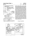
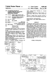
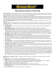
FIG. 1 is a pictorial view of the hand-held electronic
spaceship battle game;
28. Thus, when the defending spaceship moving lever
17A is pressed, point 38 moves upward to mesh with
rack teeth 39 and forces the rack bar 28 and the wand
coupled thereto to the right. The operation of defending
spaceship moving lever 17B forces the rack bar 28 and
the wand coupled thereto to the left. Thus, the wand 27
FIG. 2 is a front view of the hand-held electronic
game with the hood and viewing screen removed;
is moved left or right responsive to pressure on the
FIG. 3 is a sectional side view of the hand-held elec
tronic game;
FIG. 4 is a plan view of the mechanical linkage ar
defending spaceship moving push button levers 17A
and 17B.
Means are provided for normally maintaining the
pawl bar 29A clear of the rack. More particularly, wish
hand-held electronic game;
30 bone springs, such as springs 41, are positioned at pivot
FIG. 5 is a partial view of the front LED invader
point 34. The lever 17B and its associated pawl rod 29B
board;
are mirror images of lever 17A and pawl rod 29A; con
rangement used for moving various components of the
FIG. 6 is a partial view of the rear barrier board;
sequently, the description of the lever 17A and pawl
FIG. 7 is a plan view of the defending spaceship
rod 29A suffices for lever 17B and pawl rod 29B.
wand including ratchet rack; and
35 ~ The location of the wand 27 is automatically, electri
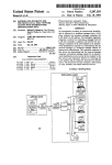
FIG. 8 is a schematic of the electronics used in con
cally tracked by means, such as contact segments 42A
trolling and depicting the active elements of the hand
and 42B, shown on the back of board 19, aligned with
held spaceship battle game.
columns 21A and 21B in conjunction with contact strip
In FIG. 1 the pictorial view of the hand-held elec
43. A contact or brush 44 on the wand makes contact
tronic spaceship battle game 11 shows the outer cover
simultaneously with the conducting segments corre
12 having a hood section 13, a viewing screen 14 and a
sponding to the. appropriate column and the contact
pair of handle portions, one of which is seen at 16. On
strip.
the handle portion is seen a defending spaceship posi
Thus, when the wand is located so that the defending
tioning push button lever switch 17A and the electrical
?ring switch 18.
spaceship is aligned with column 21A, then contact 44
45 completes a circuit from segment 42A to strip 43. This
The view of the hand-held game in FIG. 2 is with the
cover 12 removed. Therein is shown means for depict
indicates to the micro-processor that the defending
spaceship is in a position to ?re its death ray at the
invading spaceships of column 21A. It also is in a posi
tion, of course, to be destroyed by the bombs pro
ing a plethora of invading spaceships. More particu
larly, a six by ?ve matrix of LED’s is shown on board
19. The matrix comprises six columns of LED’s 21A
through 21F. Each column has ?ve rows 22A through
grammed to be dropped by the invading spaceships of
column 21A.
Means are also provided to automatically indicate to
the control means, such as the micro-processor, when
22E. Initially, all 30 LED’s are lit. In a preferred em
bodiment the invading spaceships comprise yellow
LED’s.
Barrier means are provided which may be aligned
the defending spaceship is aligned with one of the barri
ers 23A through 23F. This means is shown, for example,
in FIG. 2, as conducting segments 46E and 46F on the
board 47 which holds the barrier LED’s 23A through
with each of the columns. More particularly, six LED’s
23A through 23F are shown beneath each of the col
umns 21A through 21F. These LED’s in a preferred
embodiment are green.
Defending spaceship indicating means are provided.
More particularly, a defending spaceship is indicated by
60
23F. Spaced apart from conducting segments is con
ducting strip 48. When the wand 27 is positioned in
alignment with barrier LED 23E, for example, then a
contact or brush 49 on wand 27 completes a circuit from
an LED 24 seen, for example, in FIG. 3. The spaceship
LED 24 is aligned with a death or laser ray indicating
means. More particularly, LED’s 26A through 26G are
segment 46E to strip 48.
26G are mounted on a horizontally positioned wand
means causes the board to move in a ?rst lateral direc
assembly 27.
tion, regardless of whether 17A or 17B is activated; and
Linkage and mechanism means are provided for mov
ing the board 19 containing the spaceship invaders re
shown aligned with spaceship LED 24. Both the space 65 sponsive to the operation of either of the defending
spaceship moving levers 17A or 17B. The moving
ship LED 24 and the death ray LED’s 26A through
4,345,764
5
in the opposite lateral direction, after reaching the fur
thest lateral point in the ?rst direction.
7
-,
The linkages and mechanism are shown particularly
in FIG. 4. As shown therein, the pawl rods 29A and 29B
have affixed thereto cones 51A and 51B, respectively.
The cones abut the top surfaces of links 52A and 528,
respectively, to maintain those links in a relatively-hori
zontal plane.
The links, as seen in FIG. 2, are attached to the verti
cal portion of the defending spaceship moving lever.
6
the defending space ship all in the same plane. More
particularly, a two-way mirror 77 is shown mounted in
the game 11 parallel to the viewing screen 14.
Thebarrier board 47 is mounted toward the rear of
cover 12 in any well known manner. The barrier
LED’s, such as LED 23D, are shown extending
through an extended aperture, such as aperture 20 in
matrix board 19. Column 21D of the matrix is shown
mounted on board 19 in FIG. 3. The wand 27 is hori
zontally placed beneath the re?ecting surface of two
For example, as shown in FIG. 2, link 52A is attached
way mirror 77. Thus, a player looking through the
by any well known means, such as fastener 53, to por
viewing screen 14 and hood section 13 sees the matrix
tion 33 of lever 17A.
of invading spaceships, the barriers and the defending
The link 52A is shaped to avoid abutting rack sup
spaceship all in the same plane.
porting standard 54A. A second rack supporting stan 15 Means are provided for powering the system. More
dard 54B is shown spaced apart from standard 54A.
particularly, batteries, such as battery 79 shown in a
Another set of standards 56A and 56B are positioned
battery container 81 mounted on the base 83 of hood’
opposite standards 54A and 54B, respectively, and
section 13., The base 83 of the hood section sets upon the
closer to the front portion of the game. The link 52B is
base 84 of the hand-held electronic game. Mounted to
shaped so that it does not abut standard 56B.
20 the base are the pivot pedestals, such as pivot pedestal
When the lever 17A is operated, the link 52A moves
35. Also mounted to base 84 is a loud speaker 86 for
laterally to the left causing a crank 57, comprising circu
providing the sound effects that go with the game. For
lar portion 58 and handles 59A and 59B, in turn counter
example, throughout the game there is the “heartbeat”
clockwise. The movement of crank 57 counter-clock
sound effect which varies in tempo-increasing as the
wise causes pawl link 61 to move diagonally away from 25 game progresses.
the front of the game or away from the viewing screen
Means are provided for indicating to the electronic
14. The pawl link 61 has a cut-away section 62 made
controls associated with game ‘the relative position of
particularly to avoid abutment with standard 54A. The
the invading space ships and 'the barrier strips. More
pawl link 61 is attached to crank 57 through crank han
particularly, contact or brush means 87 mounted at the
dle 63. The pawl link 61 terminates in a pawl 64 at its 30 rear of board 19 individually connects conductive seg
end away from the crank.
\
ments 88D, 88E or 88F to conductive strip 89, when
Lost motion means are provided to isolate the move
ever the invaders and the barrier LED’s are aligned.
ment of link 52A‘ from the movement of link 52B and
Thus, if the matrix board has moved to its left limit, then
vice versa. More particularly, extended apertures in
the brush 87 connects segment 88F to strip 89. When
links 52A and 52B are provided at the crank handles 35 the board is moved to its right limit, then brush 87 con
59A and 59B, respectively. Thus, when the crank 57 is
nects segment 88D to conducting strip 89.
moved by link 52A, then the crank handle 59B moves in
As shown in the schematic of FIG. 8, the electronic
extended aperture 66B without effecting link 52B. Simi
heart of the control of the hand-held game is the micro
larly, when crank 52 is rotated around pivot point 67
processor or controller 91. In a preferred embodiment a
responsive to the actuation of link 52B, crank handle 40 National Semi-Conductor COP 421 micro-controller is
59A moves in extended aperture 66A with no effect on
used.
linkage 52A.
The micro-controller 91 has a plurality of outputs L0
The diagonal‘ movement of pawl link 61 causes
through L7 which are used to control the energization
ratchet wheel 68 to rotate in a clockwise direction.
of the LED’s, including the invaders, the barriers, the
Means, such as resilient retainer 69, assures that pawl 64 45 defending spaceships and the death ray by controlling
meshes with the teeth of ratchet wheel 68. Ratchet lever
the power to the cathodes of the columns of the LED’s.
71, pivoted around pivot point 72, assures that the
In addition, the micro-controller 91 includes D register
ratchet wheel 68 turning around pivot 73 can only ro
outputs and G register outputs connected to the bases of
tate in a counter-clockwise direction. Thus, as pawl link
transistors QA - QB and Q1, Q2. The collectors of the
61 moves diagonally towards the front of the game 50 transistors are coupled to the anodes of the rows of
resonsive to releasing lever 17A, for example, and the
LED’s. In addition, the micro-controller 91 also pro
consequent movement‘ of the lever to its normal position
vides a serial 1/0 register which provides a serial output
with the consequent movement of link 52A back to its
SO.
.
~
_
*
normal position, the crank 57 rotates counter-clockwise
A double-pole, single-throw, on-off switch 92 is
moving pawl link 61 towards the front of the game. 55 shown. When switch 92 is operated “on”, battery is
Any force on the teeth of ratchet wheel 68 cannot move
coupled through the switch conductor 93, diode D1,
the ratchet wheel clockwise, because of ratchet lever
conductor 94 to the‘battery input 11 of the controller. In
71.
.
.
Accordingly, each time lever 17A or 17B is operated,
the wand 27 is moved either right or left relative to the
addition, thepositive battery is supplied to the reset
terminal 4 through conductor 96 to reset the registers
and the‘ like. The timing is set where the clock input 3 of
stationary barrier strips, for example. At the same time
the controller is connected to the junction of timing
resistor R1 and timing capacitor C1 which are serially
pending on its previous position and the position of the
connected from conductor 94 to the ground bus 97.
ratchet wheeling crank. The space invader matrix board
A ?lter capacitor C2 is connected from conductor 94
19 is attached to the ratchet wheel 68 through the off 65 to ground bus 97. Ground conductor 97 is also ‘con
the spaceship invader matrix is moved right or left de
centered handle 74 and link 76.
a
The showing of FIG. 3 shows the means for depict
ing the invading spaceship matrix, the barrier strip and
nected to the ground input of controller 91.
.
I The operation of on-off switch 92 to, “on” also
supplies positive voltage through conductor 98, diode
'
7
4,345,764
8
D2 and conductor 99 to the emitters of the series of
applied from the micro-controller to the LO terminal
PNP transistors 101, previously referred to, enabling
and sequentially through the DO terminal D1, terminal
those transistors.
Another ?lter capacitor C3 is connected between
ground bus 97 and the cathode of diode D2. The con
ductor 99 is also coupled through conductor 102 to the
emitter of PNP transistor Q3. Conductor 102 is con
nected through resistor R2, conductor 104 to one side
of loud speaker 86. The other side of loud speaker 86 is
connected through conductor 103 to the collector of
D2, terminal D3, terminal GO or the terminal G1.
If, at this time, the defending spaceship is aligned
with column A, and not behind a viable barrier, then the
spaceship will be “hit” and “destroyed”. The micro
controller knows the position of the spaceship at the
time of dropping of the bomb and indicates the destruc
tion of the spaceship by a burn and a distinctive noise
transmitted through the loud speaker 86. The player
still has two remaining defending spaceships.
NPN transistor ampli?er Q4.
If, while the spaceship and the invaders are aligned,
the player presses the ?re button 18, a low signal is
The base of transistor Q3 is connected through resis
tor R3 to the sound output S0 of the micro-controller
91. The collector of transistor Q3 is connected through
a voltage divider comprising resistors R4 and R6 in
transmitted from the G3 terminal of micro-controlled
91 through diode D6, ?ring switch 18, conductor 116 to
the G1, resistor R12 to'the'base of transistor Q2. This
series. The base of transistor Q4 is connected through
conductor 106 to the ground bus 97. Thus, sound signals
presents a low signal at the G2 terminal of the micro
from the controller activate the audio ampli?er to cause
the loud speaker to produce the required sounds.
When the game commences, the processor is pro 20
grammed to provide negative low signals to points D0,
D1, D2, D3, G0, G1 and G2. This causes transistors QA
through QE to conduct responsive to low signals at
points L0 through L5. At this time there is no low signal
at G2. Thus, transistor Q2 does not conduct. There is a
controller.
Responsive to that low signal, a low signal is applied
sequentially to the L0 through L7 terminals of the mi
ere-controller. The signals, in conjunction with the low
signal on the base of transistor Q2, cause LED’s 26A
through 26H to sequentially light up simulating the
movement of the death ray.
Since at this time the death ray LED’s of the wand
barrier LED’s 23 to energize. There also is a low signal
overlap the aligned invading spaceships, the ?rst in
vader overlapped LED is “destroyed” by the death ray.
at L2 causing the defending spaceship 24 to energize.
Responsive to the “destruction”, the micro-controller
At the beginning of the game, the barriers and col
umns of invading spaceships may or may not be aligned.
Similarly, the wand may be in a position where the
spaceship is or is not aligned with the barrier. The
player of the game operates levers 17A‘ and 17B to
sends a signal out through S0 to cause the loud speaker
to broadcast a distinctive noise indicating the “destruc
vertical conductor on the matrix, such as conductor
113, resistor R LA and back to the terminal LO of
When the barrier LED’s are between the invaders
and the defending spaceship, neither the invaders nor
micro-controller 91. The micro-controller is apprised of
the position of the defending spaceship relative to the
45 However, the randomly strewn bombs of the invaders
low signal at G1, and transistor Q1 conducts causing the
tion” of an invading spaceship. The “destruction” of the
invading spaceship is also recorded in the memory for
compilation of the ?nal score.
If a dropped bomb and death ray strike each other,
move the wand so as to cause the spaceship 24 to be
35 then the dropped bomb is not “destroyed”. The “de
positioned as desired.
struction” of an invading spaceship stops the death ray;
The position of the spaceship relative to the barriers
so that the death ray can “destroy” only one invading
is indicated to the micro-processor. For example, when
spaceship per ?ring. If the death ray is activated when
the brush 49 abuts the contact segments 46A through
the defending spaceship and invaders are not aligned,
46F on the board, a circuit is completed from G2 of
then the micro-controller causes a distinctive noise to be
micro-controller 49 through conductor 111, diode D3,
broadcast indicating a “miss”.
'
contact strip 48, brush 49, conducting segment 46, a
barrier strips in this manner.
Similarly, the position of the defending spaceship
relative to the columns of invading spaceships is indi
cated to the board when brush 44 abuts one of the con
ducting segments 42. Contact of the brush, segment and
strip completes a circuit extending from terminal G3 to
terminal L0 through L5 of the micro-controller 91,
through conductor 114, diode D4, conductor 43, brush
44, segments 42A through 42F through conductors,
such as conductor 113, a resistor, such as R LA, and
terminals, such as L0. The described circuit indicates to
the micro-controller that a defending spaceship and a
column of invaders are aligned. At this time the space
the defending spaceship can “destroy” each other.
act to gradually “destroy” the barriers. Similarly, when
the death ray of the defending spaceship “hits” the
barrier, it also partially “destroys” the barrier. In a
preferred embodiment the barrier is “destroyed” after
being “hit” 15 times either by bombs or death ray shots.
As the barrier is “destroyed”, its light becomes less
intense. Once the barrier is “destroyed” it no longer
protects thedefending spaceship from the bombs of the
invaders.
The alignment of the invaders and the barriers is
indicated when the metallic strip 87 on the board 19 is in
contact with the conducting element 89 on the board
47. The conducting element 89 is coupled to terminal
G0 of micro-controller'91. The metallic strip 87 is con
ships; and the invaders are vulnerable to the death ray 60 nected from a low signal at terminal G1 of micro-con
troller 91 through conductor 117, diode D6 and con
of the defending spaceship.
-
ship is vulnerable to the bombing by the invading space
ductor 118 to metallic strip 87. The receipt of the low
signal at terminal G0 indicates to the controller that
there is alignment between the invaders and the barrier.
controller sends signals sequentially, for example, down
a column. At that time if, for example A column is 65 When there is no low signal on G1, then the barriers
have been “destroyed”.
dropping the bombs, then the light of LED AA will
The micro-controller 91 may also be programmed to
brighten followed sequentially by the lights of LEDs
replace “destroyed” invaders by moving the surviving
BA, CA, EA and DA. This occurs when a'low signal is
The bombs are dropped randomly. With the initiation
of the micro-controller a bomb occurs when the micro
4,345,764
invaders into the closer position of the “destroyed”
invader. If a whole column of invaders is “wiped out”,
the surviving invaders may be randomly moved into
that column.
.
As the game progresses and invaders are “de
stroyed”, the tempo is automatically increased—both
the background “heart thumping” sound and the drop
10
aretwiped vout, then GAME STATUS is set to POST-I
GAME. If there are defending spaceships remaining,
the number of defending spacehips is beeped and
blinked and play continues.
If the “laser on” flag is up, the laser LED’s are se
quentially lit brightly and the laser sound is broadcast.
When the “bombs on” ?ag is up, the LED’s in that
ping of the random bombs increases in tempo. In addi
column sequentially burn. If ?ag 33 is active, all tasks,
tion, the surviving invaders may tend to move “down”
to the rows closer to the defending spaceship; thus,
except TASK 1 are omitted. Obviously, this shortens
giving the defending spaceship less time to “dodge”
bombs.
The sounds to be broadcast are inserted when the
GAME block ?ips the speaker on and inserts variable
If all of the invaders are “destroyed” before the three
defending spaceships are “destroyed”, then a whole
new array of invaders is provided by the micro-con
troller, along with a new defending spaceship. Thus, the
player obtains a second game. However, the tempo of
the second game is automatically greater than the
tempo of the ?rst game.
Here again, after a given number of invaders are
“destroyed”, the tempo further increases and then con
turning on the LED’s to be burnt and inserting delays in
the energization of those LED’s.
In the POSTGAME block, the initiation array is
centered so that all remaining enemy or invading space
ships can be readily seen. The background sound is on;
?ag 33 is set to suppress all other activity, such as laser
and missile on. The POSTGAME block monitors ?re;
and, if ?re has been held onfor a suitable length of time,
tinually increases throughout the remaining game mak
POSTGAME calls for a FRESH ARRAY. Each
the large loop.
delays in the large loop. The burns are accomplished by
ing it more difficult to “destroy” the entire array of
FRESH ARRAY gives the, player one defending space
invaders prior to the three defending spaceships being
ship as a bonus. Each FRESH ARRAY moves and
“destroyed”.
At the beginning of the program the power is turned
on; i.e., “POWER UP”. The micro-processor 91 ,has an
25 drops bombs at a faster tempo.
Thus, the player can force the game to a higher skill
gram is comprised of a large main loop. Alternate paths
lever, then he has actually achieved by wiping out all of
the invaders. However, his activity at the higher skill
level is limited to one spaceship. This allows the player
to observe the higher tempos and practice at them. The
unique feature can be used repetitively to get to higher
and higher skill levels.
are taken within the main loop, depending on the status
POSTGAME also indicates the number of arrays
automatic power up reset. The power up reset clears the
accumulator, resets the E register of the micro-proces
sor and sets the RAM pointer “B” to 0,0. Then, all
RAM outputs are set to binary l’s (Hex F). The pro
“killed” by the invading spaceships in code by blinking
of different “?ags” or outputs during the transversal of
the loop. A RAM cell, herein called GAME-STATUS, 35 appropriate barrier lights. FRESH ARRAY sets all
RAM outputs to F, except one corner containing the
selects one of the paths of the loop. The loop paths
number of defending spaceships and the score. The
comprise OPENING, GAME, POSTGAME and
program then goes to OPENING. When going to
FRESH ARRAY.
‘
Setting all of the RAM outputs to the binary l’s sets
OPENING from FRESH ARRAY, the player gets one
the GAME STATUS to F which consequently selects 40 defending spaceship.
The large loop always ?ows through a block called
the OPENING block. The OPENING program por
“MAIN LOOP”. MAIN LOOP broadcasts back
tion bleeps and blinks for each of the defending space
ships in the player’s possession. The background (hear
ground sound, if the control ?ag is on background
sound. MAIN LOOP also decrements display row
beat) sound is turned on. The barriers are set up with all
fresh values, and then the invaders are set in the matrix. 45 pointer correcting it as required, assembles the list out
put word and stores it in the appropriate RAM cells.
GAME STATUS is then set to GAME and the path
MAIN LOOP turns the display off. It reads the inputs
goes through the GAME block. GAME is the block or
(?re button and three barrier switches read through L
path followed during the actual play. The path continu
PORT and 2 reads of one byte each outputs new display
ation during the play is controlled by ?ags. There are
?ags for: invader hit; spaceship hit, laser on and bombs 50 to G and L PORTS) and turns display back on.
on.
If any of these ?ags are tripped, then initiation house
keeping values will be set in the GAME block followed
TASKLIST follows MAIN LOOP and it directs the
program through one of the six tasks based on the value
of the display row pointer. If ?ag 33 is active, then all
by the setting of ?ag 33. Flag 33 is the ?ag used to
tasks, except TASK 1, are omitted. The tasks are fol
remember that one of the other ?ags is up and initiation 55 lowed by the equalizing delays. The DELAYS are
followed by STATUS which tests GAME STATUS
housekeeping has been down. Flag 33 also controls ?ow
through the TASKLIST.
and directs the program accordingly. The large loop is
When it’s an “invader hit” ?ag that is up, the hit . now closed.
TASK 1 provides background sound and advances
invader is turned off. The score is incremented, and the
invader hit sound is broadcast. If all the invaders are 60 all timers. Some of the timers are ?xed speed and ad
vance with the number of frames displayed. It must be
“dead” with this invader hit, the GAME STATUS is
noted that while the array appears to be on continu
changed to call for a FRESH ARRAY. If the “space
ship hit” ?ag is up, the defending spaceship is burnt, the _ ously, it is actually blinking at a speed; i.e., the number
of frames per second, suf?cient to cause it to appear to
number of spaceships available to the defender is de
creased, and the spaceship hit sound is broadcast. The 65 the eye to be on continuously.
burning of the defending spaceship is accomplished by a
temporary high power transmitted to the spaceship to
cause it to brighten. If the three defending spaceships
So, some of the timers use the frame MUX rate as
their base. Other timers are variable and speed up as the
score increases. This is what causes the game to acceler
4,345,764
11
12
ate as the player goes through'a single array and as he
accompanied by an increase in the tempo of the back
wipes out more and more arrays of invaders.
ground sound.
TASK 2 moves the array left and right. The array
moves left until a “live” invader is sensed in the far left
defenders are destroyed, a new array is provided and
If an array is completely destroyed before the three
begins movement with the speed faster than that of the
previous array. An extra spaceship is awarded to the
player when an array is successfully obliterated.
The game ends when all defending spaceships are
destroyed. At that time the score is indicated by the
(blind) corner. The array is then switched to move to
the right and continuous until a “live” invader is sensed
in the far right (blind) corner. The motion speeds up as
the score increases.
TASK 3 ?res invader bombs down upon the defend
ing spaceship.
10 array.
The enemy bombs drop one at a time from the ?rst
the ?re button.
two arrays and two at a time from arrays 3 on. A bomb
TASK 5 translates the input information obtained
and laser do not cancel when on the same path. If no
TASK 4 ?res a laser up at the invaders in response to
during the MAIN LOOP into actual column numbers
barrier separates the two, then both the invader and the
15 defender are vulnerable to weapons simultaneously
for use by other parts of the program.
TASK 6 assembles a barrier word for driving the
?red on the same path. The spaceship’s laser always
barrier LED’s from the barrier values. There is one
?res faster than the invaders’ bombs.
nibble for each barrier. These are initiated at different
If a defender is hit, it will beep one time per spaceship
strengths to adjust for edge effects by the OPENING.
left. When all the defenders are destroyed by the invad
Each hit upon a barrier increments the value by 2 with
ers, the surviving invaders are frozen on the array and
a cutoff value of 15. As the value approaches 15, the
the four left side barriers are lit to tell how many arrays
barrier is blinked, the signal gets weak. This is accom
are cleaned out. From left to right, numerical values fo
plished by providing alternate output values of the bit
the four barriers are 1, 2, 4 and 8. The number of arrays
controlling the barrier LED. At 15, the barrier goes
cleaned out is indicated by the sum of any of the four
out.
25 scoring barriers that are blinking.
In summary, when the game is turned on, the defend
The program was used to develop a program of
ing spaceship will signal on sound and one blip for each
of the three ships with which the player starts. The
ROM values for the micro-processor using the COP 400
defending spaceship seeking to destroy the defending
400 Micro-controller Family Chips User’s Manual—N
Product Development System User’s Manual 0 1978
barriers then the array of 30 enemy invaders appears in
and the addendum of 1979, National Semi-Conductor
view. The enemy invaders drop bombs at the player’s 30 Ser. No. 420305548-00 in conjunction with the COP
spaceship. The player controls the move of the space
SEMICON Serial Number 420305785-001 dated Janu
ship and the ?ring-of the laser gun attempting to destroy
ary 1979, all available through National Semi-Conduc
as many of the invaders as he can.
tor Company.
The invading spaceships are located on one plane. 35
The defending spaceships are located in a plane substan
tially normal to the plane of the invaders. Six barriers
?xed to a plane parallel to and spaced apart from the
.
~ Typical ROM values for a preferred embodiment are
shown on the accompanying Table 1.
While the principles of the invention have been de
scribed above in connection with speci?c apparatus and
applications, it is to be understood that this description
is made by way of example only, and not as a limitation
invaders’ plane are used to help protect the defender
from the dropping bombs. As the invading arrays be
come increasingly depleted, the movement of the invad
ers and the frequency of the bombs dropping increases
on the invention.
TABLE 1
ROM VALUES:
000
00
0F
010
74
72
020
AF
33
030
SF
61
040
51
CO
050
29
5F
060
83
83
070
20
48
080
63
CA
090
00
58
0A0
84
33
0B0
22
F2
0C0
4E
23
ODO
5F
22
0E0
48
2B
OFO
C4
05
100
2B
13
110
15
23
12
9D
81
5F
8B
63
05
49
FA
F6
A6
00
A3
F4
01
30
C6
87
120
5B
21
E9
130
140
A5
33
43
57
5C
33
150
160
D3
6A
170
68
A8
04
180
2C
190
1A0
1B0
1C0
43
76
06
Al
EE
87
28
9F
B2
77
77
62
60
B4
23
63
CE
00
33
5F
12
33
33
44
03
05
2E
44
85
60
A8
71
04
7O
78
EB
3E
5F
B3
A4
C0
59
A7
48
23
97
65
06
68
A5
03
82
33
46
2B
A8
C3
71
05
4B
48
62
48
11
C7
F6
33
12
98
15
l1
48
7A
04
E8
E6
2E
23
4B
16
12
77
52
2C
23
40
88
00
D9
09
97
51
48
33
33
21
A3
73
5D
72
04
13
27
5F
B5
23
El
33
48
CC
23
3C
6D
48
83
33
C2
2C
D1
68
40
62
88
88
F1
93
61
00
23
48
48
49
05
87
9F
43
23
3C
5F
80
48
48
60
00
00
0O
50
2B
05
00
5,5
6B
8B
68
04
60
61
5F
96
00
66
F6
0E
0O
23
01
40
21
83
A4
71
63
B4
00
13
C4
D8
B2
21
CF
2D
21
CF
2F
33
EA
83
7C
82
2B
23
7F
05
46
21
19
54
19
51
78
F0
05
CE
2C
07
57
9B
43
AF
7E
7B
2D
05
A8
9B
03
51
13
93
00
DF
5F
5F
29
FD
63
48
53
60
33
08
00
18
33
23
49
O5
B5
E8
E6
2E
9B
78
00
0F
E9
DD
1F
2C
27
19
02
6F
88
0F
00
12
61
A3
48
58
4B
5C
86
16
01 i
79
0O
A5
42
FC
05
54
A1
16
21
14
E8
33
2E
5B
13
33
23
39
23
79
98
78
6B
78
A4
78
70
08
5F
06
13
63
6O
06
60
33
60
00
48
11
05
0O
06
46
00
77
78
C3
OF
61
80
00
SE
D1
60
84
33
99
AF
48
00
6A
F9
A8
33
35
00
0O
00
32
05
33
69
59
44
00
O0
35
50
A3
00
21 _ F2
33
3E
6B
D9
48
8D
90
F5
00
O0
00
56
68
3C
A8
2B _
F9
61
61
80
8D
F8
E3
6B
F2
9F
8D
16
2D
70
61
A8
46
60
C2
51
9D
29
33
D4
9D
0E
06
49
1A
4,345,764
13
14
TABLE l-continued
lDO
2B
42
61
BF
8D
A8
6A
28
A8
2D
43
33
83
99
F8
9F
1B0
mo
73
36
60
A1
29
80
2C
2F
' 01
7E
E9
6B
6B
20
E5
F8
FA
_ 2B
11
4B
F8
20
All
4B
93
A8
HF
2B
F3
05
-23
54
AF
ROM VALUES:
200
5c
68
7A
09
8B
62
09
19
97
DC
23
01
06
23
210
220
230
240
250
00
12
49
23
613
B0
12
2B
28
9D
20
SD
03
51
FA
D5
E6
F8
c5
23
70
7D
75
AC
00
33
AC
2E
97
58
94
7A
42
AC
AC
AF 2B
AC 19
48 1 42
33
94
90
AC
13‘
7C
2E
99
2E
DE
33
46
D3
01
AC
B3
33
D9
EA
AF
99
B3
2E
1A
AC
F1
83
01
32
'23
213
48
2A
13
14
42
260
270
280
290
2A0
2B0
2C0
2D0
250
2F0
22
04
Al
AC
33
55
c6
Al
06
21
06
EC
07
33
B6
B0
05
83
Al
- AC
04
2E
04
92
8B
A1
50
93
23
213
DE
47
' 16
AF
ES
7F
05
EB
01
13
2E '
20
07
01
AA
2C
51 '
33
52
F6
47
_ F8
04
DA
05
45
09
95
40
El
20
4c
16
38
56
AA
2E
03
06
2D
F8
45
99
99
E6
38
4B
BA
2c
43
4D
28
F7
DC
5A
23
CB
23
47
68
45
7A
23 '
D1
06
36
215
36
AC
5F
0A
28
00
13
68
21
43
3E
2E
El
32
8B
5E
AF
E9
{62
09
50
13
213
01
cc
CE
05
08 v
C9
11
05
AC
46
EF
AA
D1
33
68
33 .
Ac
51
E1
11
22
00
09
B6
73v
B8
03
E0
00
62
06
00
01
E6
69
8F
Ac
EA
57
59
300
310
2B
58
4B
8D
2C
A8
77
9F
19
AF
23
A8
00
2F
ll
23
00
0A
08
50
16
05
B2,
23
16
A0
89
DE
23
2B
15
46
320
2F
15
06
3F
8B
E3
48
9D
05
58
58
63
3F
330
340
350
360
370
380
390
3A0
3B0
3C0
3D0
3130
23
01
58
05
82
63
c7
28
00
08_
v85
3A
15
AC
AC
51
68
59
38
05
B1
89
63
50
58
9D
96
CC
E9
70
' 7A
0E
63
85
DA
33
63
00
AC
D4
23
AA
33
50
A4
O6 '
B2
3E
37
59
9D
05
28
33
85
23
39
04
33
48
77
21
88
55
0F
B8
89
18
AF
63
B2
23
Ac
B4
AC
D4
50
7A
03
5F
06
B5
BF
0A
78
33
2B
33
68
33
D9
48
53
08
87
58
20
B8
4B
B7
73
86
AB
23
63
89
48
40
4c
99
2c
99
47
89
38
98
BF
AA
A3
40
23
DE
4D
EC
69
03
83
32
23
58
B2
23
39
D4
9D
D4
55
CD
D3
88
0A
44
BF
A0
23
06
76
23
63
D1
AB
B5
53
23
9B
63
7F
BF
DF
BF
F7
FB
FD
FE
FF
DF
FF
EF
F7
3F0
.'
'
What is claimed is:
1. A hand-held programmed electronic game for
playing by individuals holding said electronic game,v
said game comprising ?rst electronically controlled
lights for depicting invaders and bombs,
second electronically controlled lights for depicting
defenders and death rays,
third electronically controlled lights visually inter
posed between said electronically controlled lights
depicting said defenders and said electronically
controlled lights depicting invaders for depicting
barriers impenetrable by said bombs and death
rays,
said ?rst and second electronically controlled lights
af?xed in ?rst and second planes respectively, and
means for causing individuals to see said ?rst, second
and third electronically controlled lights in a single
plane.
35
. 44
'
- 59
00
29
E1
63
413
B7
D7
AC
39
54
33
05
88
5D
B2
33
1E
AC
23
05
21
2D
B8
23
00
22
84
2c
00
09
15
50
63
42
8B
98
12
84
86
33
00
‘ FB
FD
FE
said second electronically controlled lights compris
. ing a single column of said lights mounted on a
wand.
5. The hand-held programmed electronic game of
claim 4 wherein an extended aperture is provided in said
?rst ‘board below said array to provide visible access to
said third electronically controlled lights.
6. The hand-held programmed electronic game of
claim 5 wherein said means for causing the players to
see said ?rst, second and third electronically controlled
lights on a single plane comprises two-way mirror
45 means angularly mounted between said ?rst and second
planes.
7. The hand-held programmed electronic game of
claim 6 including means for selectively moving the
wand to the right or to the left to avoid being hit by
bombs and to hit the invaders with the death rays.
8. The hand-held programmed electronic game of
claim 7 wherein the means for selectively moving the
2. The hand-held programmed electronic game of
wand also moves the ?rst board.
claim 1 wherein the ?rst and second planes are at right
9. The hand-held programmed electronic game of
angles to each other.
55 claim 8 wherein said means for moving the wand with
3. The hand-held programmed electronic game of
said second electronically controlled lights also moves
claim 2 wherein said ?rst and third electronically con
the ?rst board with said ?rst electronically controlled
trolled lights are in substantially the same plane and
lights alternately as far as it will go from one side to the
spaced apart from each other.
other side.
4. The hand-held programmed electronic game of
10. The hand-held programmed electronic game of
claim 3 wherein said ?rst electronically controlled
claim 9 including handle means on said game, whereby
lights comprise an array of electronically controlled
said player can hold said game while manipulating the
lights mounted on a ?rst board,
controls and looking into the viewing screen,
said array comprising a plurality of columns and a
said means for selectively moving the wand com
prises push-button lever means mounted in said
plurality of rows,
said third electronically controlled lights comprising
a single light for each column of said array
mounted on a second board, and
handle means,
pawl means attached to said push-button lever means,
ratchet means moved by said pawl means, and
.
4,345,764
'15
means;
umns with said barriers.
_
_
17. The hand-held programmed electronic game of
claim 16 including means for increasing the tempo of
operation of the game to enable the game to be played
11. The hand-held programmed electronic ‘game of
claim 10 including lost motion linkage means coupling
said push-button lever means to said ?rst board,
at different skill levels.
whereby said ?rst board is moved alternately right and
left responsive to the operation of said push-button
18. The hand-held programmed electronic game of
claim 17 including means for automatically increasing
the tempo of the game responsive to the destruction of
complete arrays, and
means for enabling the increase of the tempo of the
game independently of the destruction of complete
lever.
12. The hand-held programmed electronic game of
claim 11 wherein said third electronically controlled
lights remain stationary during the movement of said
?rst board and said wand, and
means for selectively ?ring said death ray.
13. The hand-held programmed electronic game of
arrays.
19. A hand-held programmed » electronic game for
playing by individual players holding said electronic
claim 12 wherein said program is contained in a micro
processor, and
means for sensing the when said lights depicting de
fenders and death rays are aligned with said lights
20
depicting invaders and bombs.
14. The hand-held programmed electronic game of
claim 12 including means for sensing when the electron
ically lights depicting defenders and death rays are
aligned with the lights depicting barriers.
'16
contact material to indicate alignment of said col
means for attaching said wand to said ratchet
game,
said game comprising a ?rst set of LED’s mounted on
a ?rst board,
said ?rst set of LED’s arranged in a matrix array of
columns and rows and depicting invaders,
a second set of LED’s mounted in a single column on
a wand depicting a defending spaceship and its
death ray,
said wand mounted at right angles to said ?rst board,
and
means for causing the players to see said ?rst board
and said wand on a single plane.
of said ?rst electronically controlled lights depicting
20. The hand-held programmed electronic game of
invaders are aligned with said third electronically con
claim 19 wherein said ?rst board has an extended aper
trolled lights depicting barriers.
30 ture therein,
second board means having an LED thereon for each
16. The hand-held programmed electronic game of
15. The hand-held programmed electronic game of
claim 12 including means for sensing when said columns
25
claim 12 wherein contact material is mounted on said
of said columns, and '
'
said extended aperture means in said ?rst board en
?rst board aligned with each of said columns,
abling viewing of said second board LED’s in said
invader column sensing contacts mounted on said
wand for completing a circuit from said ?rst board
one plane.
21. The hand-held programmed electronic game'of
contact material to indicate alignment of said wand
with said column,
claim 20 wherein said means for causing said players to
see the LED’s on a single plane comprises a two-way
contact material mounted on - said second board
mirror angularly mounted between said ?rst board and
aligned with each of said barrier lights,
said wand.
barrier light sensing contacts mounted on said wand
for completing a circuit from said second board
contact material to indicate alignment of said wand
with said barriers,
22. The hand-held programmed electronic game of
claim 21 including means for selectively moving said
wand to the right or to the left,
means responsive to the movement of said wand to
further contact material mounted on said second 45
the right or to the left for moving said ?rst board
board, and
alternately to the right limits and left limits,
said second board being stationary.
barrier sensing contacts mounted on said ?rst board
*
for completing a circuit through said further
50
55
60
65
it
it!
*
1|
1
UNITED STATES PATENT AND TRADEMARK OFFICE
CERTIFICATE OF CORRECTION
.
PATENT NO. 1
4, 345, 764
‘DATED
August 24, 1982
;
INVENTOR( S) :
GORDON A. BARLOW, JOHN R. KRUTSCH, RICHARD A KARLIN
It is certified that error appears in the above-identified patent and that said Letters Patent
are hereby corrected as shown below:
6
Col.
5,
line 24:
"in" should be -—to--.
>
-
Signed and Scaled this
.
Twenty-seventh
Day Of September I 983
|SEAL|
Allesl:
.
_
GERALD J. MOSSINGHOFF
Arresting Officer
b
D
6
O
Commissioner of Parents and Trademarks