1
PSZ 19:16 (Pind. 1/07)
UNIVERSITI TEKNOLOGI MALAYSIA
DECLARATION OF THESIS / UNDERGRADUATE PROJECT REPORT AND COPYRIGHT
Author’s full name : CHEN KEAN TACK
Date of Birth
: 14TH JANUARY 1989
Title
: DESIGN AND IMPLEMENTATION OF FPGA-BASED FLOATING POINT
MATH HARDWARE MODULE
Academic Session : 2012/2013
I declare that this thesis is classified as:
CONFIDENTIAL
(Contains confidential information under the Official Secret
Act 1972)*
RESTRICTED
(Contains restricted information as specified by the
organization where research was done)*
OPEN ACCESS
I agree that my thesis to be published as online open
access (full text)
I acknowledged that Universiti Teknologi Malaysia reserves the right as follows:
1. The thesis is the property of Universiti Teknologi Malaysia.
2. The Library of Universiti Teknologi Malaysia has the right to make copies for
the purpose of research only.
3. The Library has the right to make copies of the thesis for academic
exchange.
Certified by:
SIGNATURE
890114-08-5549
(NEW IC NO/PASSPORT)
Date:
NOTES:
*
24TH JUNE 2013
SIGNATURE OF SUPERVISOR
ASSOC. PROF. DR. MUHAMMAD
NASIR BIN IBRAHIM
NAME OF SUPERVISOR
Date:
24TH JUNE 2013
If the thesis is CONFIDENTAL or RESTRICTED, please attach with the letter from
the organization with period and reasons for confidentiality or restriction.
“I hereby declare that I have read this thesis and in my/our*
opinion this thesis is sufficient in terms of scope and quality for the
award of the degree of Bachelor of Engineering (Electrical-Microelectronics)”
Signature
:
………………………….........
Name of Supervisor
:
ASSOC. PROF. DR. MUHAMMAD
NASIR BIN IBRAHIM
Date
:
24TH JUNE 2013
DESIGN AND IMPLEMENTATION OF FPGA-BASED FLOATING POINT
MATH HARDWARE MODULE
CHEN KEAN TACK
A thesis submitted in fulfillment of the
requirements for the award of the degree of
Bachelor of Engineering (Electrical-Microelectronics)
Faculty of Electrical Engineering
Universiti Teknologi Malaysia
JUNE 2013
ii
I declare that this thesis entitled “Design and Implementation of FPGA-based
Floating Point Math Hardware Module” is the result of my own research except as
cited in the references. The thesis has not been accepted for any degree and is not
concurrently submitted in candidature of any other degree.
Signature
:
....................................................
Name
:
CHEN KEAN TACK
Date
:
24TH JUNE 2013
iii
All glory be to the God above,
Special thanks to
My beloved family members who are always there for me,
Father, mother and my brothers
My friends who never complain much, accompanying me until the end of research
And also to
My supervisor who guide me through the research’s hardships
iv
ACKNOWLEDGEMENT
First and foremost, I would like to express my sincere gratitude towards my
supervisor, Associate Professor Dr. Muhammad Nasir bin Ibrahim for his invaluable
guidance, advice, comments and encouragements throughout the whole journey of
supervision during my final year project. Thus, the supervision and support that he
gave slightly help the progression and smoothness of my final year project.
Apart from that, an honorable mention goes to my friends that always support
me for their willing to share their knowledge and assist me when I faced the problem.
Without helps of the particular that mentioned above, I would face many difficulties
while doing the project or task.
Special thanks to En. Muhammad Arif bin Abdul Rahim and Dr. Usman
Ullah Sheikh who give me briefing of the final year project and research
methodology. Finally, I would like to thanks all the seminar panels for their valuable
comments.
v
ABSTRACT
This project is aimed to design and implement a FPGA-based floating point
math hardware module based on the conventional architecture of FPU and CORDIC
algorithm. Thus, the design can be used to solve various mathematical operations
such as addition, subtraction, multiplication, division, exponent, trigonometry and
hyperbolic. Then, the 32 bits single precision IEEE-754 format and fixed-point
format are used to represent floating point numbers in the design and trade-off
between these two formats are discussed based the result precision and design
performance. An efficient algorithm namely Coordinate Rotational Digital Computer
(CORDIC) algorithm is developed in the design to realize the solutions for
elementary functions such as trigonometry in faster way and lower cost as only shift
register, adder and look-up table (ROM) are required. Finally, the design is
implemented on the Altera FPGA board with an external circuit soldered on a donut
board which consists of a 16x2 character LCD, a 4x4 matrix keypad and some
important electronic components. Thus, the matrix keypad is used as input interface
and LCD as output interface. This interface circuit can be used to test the
functionality of the design without referring to the simulation waveform. In addition,
the output results displayed on LCD are in hexadecimal form of the 32 bits IEEE-754
format to ease the designer to read the result from it.
vi
ABSTRAK
Projek ini bertujuan untuk mencipta dan membuat satu modul perkakasan
matematik dengan titik terapung yang berasaskan FPGA. Ciptaan modul ini adalah
berasaskan teori seni bina FPU umum serta algoritma CORDIC. Justeru itu, ciptaan
ini dapat digunakan untuk menyelesaikan pelbagai jenis operasi matematik seperti
operasi penambahan, penolokan, pendaraban, pembahagian, eksponen, trigonometri
serta hiperbola. Sehubungan dengan itu, format IEEE-754 dengan ketepatan tunggal
bit 32 dan format titik tetap digunakan untuk mewakili titik-titik terapung dalam
cipataan ini. Selepas itu, hubung kait antara kedua-dua format tersebut dibincang
berasaskan kepada ketepatan output serta prestasi ciptaan. Selain itu, satu algoritma
berkesan yang bernama algoritma Coordinate Rotational Digital Computer (CORDIC)
digunakan dalam ciptaan ini untuk menyelesaikan fungsi-fungsi elemen seperti
trigonometri dengan cara yang lebih cepat serta kos yang lebih murah kerana ia
hanya memerlukan pengalih, penambah dan ROM. Akhirnya, ciptaan ini dibuat ke
atas papan Altera FPGA dengan satu litar luaran yang dipateri atas papan donat.
Antara komponen-komponen yang penting adalah 16x2 character LCD, 4x4 kekunci
matriks dan sebagainya. Justeru itu, kekunci matriks adalah digunakan sebagai
penyambung input dan LCD pula digunakan sebagai penyambung output. Selain itu,
litar ini juga dapat digunakan untuk menguji fungsi ciptaan tanpa merujuk kepada
keputusan simulasi. Lantaran itu, keputusan output yang dipaparkan di atas LCD
adalah dalam bentuk perenambelasan dengan format ketepatan tunggal bit 32 supaya
dapat mempercepat proses memperoleh sesuatu keputusan.
vii
TABLE OF CONTENTS
CHAPTER
1
2
TITTLE
PAGE
DECLARATION
ii
DEDICATION
iii
ACKNOWLEDGEMENT
iv
ABSTRACT
v
ABSTRAK
vi
TABLE OF CONTENTS
vii
LIST OF TABLES
x
LIST OF FIGURES
xii
LIST OF ABBREVIATIONS
xiv
LIST OF APPENDICES
xv
INTRODUCTION
1
1.1 Project Overview
1
1.2 Motivations
2
1.3 Problem Statements
3
1.4 Project Objectives
3
1.5 Scope of Works
4
1.6 Organization of the Project
4
LITERATURE REVIEW
6
2.1 Field Programmable Gate Array (FPGA)
6
®
2.1.1 Altera Cyclone II FPGA
8
2.1.2 Altera DE1 Development and Education Board
9
2.2 Floating Point Units (FPUs)
10
2.3 IEEE Standard for Floating Point Arithmetic (IEEE- 11
viii
754)
2.3.1 Single Precision Floating Point Formats
11
2.3.2 IEEE-754 Rounding Modes
13
2.3.3 IEEE-754 Exception Handling
13
2.4 Fixed-point Format
2.4.1 Q-format
2.5 Algorithms of Floating Point Arithmetic in FPU
14
14
15
2.5.1 Addition and Subtraction
15
2.5.2 Multiplication
17
2.5.3 Division
19
2.5.4 Transcendental Functions
21
2.5.4.1 Coordinate Rotational Digital Computer 22
(CORDIC) Algorithm
3
4
2.6 Related Works
25
2.7 4x4 Matrix Keypad Module
26
2.8 16x2 Character LCD Module
27
DESIGN METHODOLOGY
30
3.1 Design Stages
30
3.1.1 Design Specifications
30
3.1.2 Design Implementation
31
3.1.3 Design Testing and Verification
33
3.1.4 Flowchart of the Overall Project Workflow
34
PROJECT DESIGN AND ARCHITECTURE
35
4.1 Basic Floating Point Math Module Design
35
4.1.1 Floating Point Adder
35
4.1.2 Floating Point Subtractor
37
4.1.3 Floating Point Multiplier
39
4.1.4 Floating Point Divider
41
4.1.5 Rounding Logic
42
4.2 Efficient Floating Point Math Module
4.2.1 The Architecture of CORDIC Algorithm
43
43
ix
4.2.2 Trigonometric CORDIC Module
44
4.2.3 Hyperbolic CORDIC Module
46
4.2.4 Q-format to IEEE-754 format Converter
49
4.3 External Interface Circuit
5
6
7
49
4.3.1 Matrix Keypad Scanner
51
4.3.2 De-bouncer
52
4.3.3 LCD Controller
53
4.4 Overall Design
54
PROJECT MANAGEMENT
56
5.1.1 Project Schedule
56
5.1.2 Project Cost
57
RESULT AND ANALYSIS
59
6.1 Simulation Results
59
6.1.1 Floating Point Adder
59
6.1.2 Floating Point Subtractor
61
6.1.3 Floating Point Multiplier
62
6.1.4 Floating Point Divider
63
6.1.5 CORDIC Module
64
6.2 Interface Circuit Results from LCD Display
66
CONCLUSION AND FUTURE WORKS
67
7.1 Conclusion
67
7.2 Future Works
68
REFERENCES
69
APPENDIX A
71
APPENDIX B
92
x
LIST OF TABLES
TABLE NO.
2.1
TITTLE
List of invalid range for IEEE-754 single precision
PAGE
12
format
2.2
Unified CORDIC Rotational Mode
23
2.3
Pin Layout functions for all character LCD
27
2.4
The command control codes
28
2.5
Standard LCD ASCII Character Table
29
4.1
I/O interface description for fpu_add
36
4.2
I/O interface description for fpu_sub
37
4.3
I/O interface description for fpu_mul
40
4.4
I/O interface description for fpu_div
41
4.5
Look-up Table for Rotational Angles from 0 to 15
44
iterations (CORDIC_Circular)
4.6
I/O Interface description for CORDIC_Circular
45
4.7
Look-up Table for Rotational Angles from 1 to 15
46
iterations (CORDIC_Hyperbolic)
4.8
I/O Interface description for CORDIC_Hyperbolic
47
4.9
Pin assignments on Altera DE1 Board
50
4.10
Initialization Command data and description
53
5.1
List of Components and Materials needed
57
6.1
The detailed description of input and output operand
60
from the output waveform of fpu_add
6.2
The detailed description of input and output operand
61
from the output waveform of fpu_sub
6.3
The detailed description of input and output operand
from the output waveform of fpu_mul
62
xi
6.4
The detailed description of input and output operand
63
from the output waveform of fpu_div
6.5
The detailed description of input and output operand
from the output waveform of CORDIC module
64
xii
LIST OF FIGURES
FIGURE NO.
TITTLE
PAGE
2.1
Generic structure of an FPGA fabric
7
2.2
Cyclone II PLL block diagram
8
2.3
The schematic diagram for expansion headers
10
2.4
IEEE-754 Single Precision Formats
12
2.5
The flowchart for the conventional floating point
17
addition or subtraction
2.6
The flowchart for the conventional floating point
19
multiplication
2.7
The flowchart for the conventional floating point division
21
2.8
4x4 Matric Keypad columns and rows
26
2.9
4x4 Matrix Keypad Basic Connection Diagram
27
3.1
General Design Implementation Steps
32
3.2
The flowchart of overall project workflow
34
4.1
Block diagram of floating point adder (fpu_add)
35
4.2
Block diagram of floating point subtractor (fpu_sub)
37
4.3
Block diagram of floating point multiplier (fpu_mul)
39
4.4
Block diagram of floating point divider (fpu_div)
41
4.5
Basic Architecture of CORDIC Algorithm
43
4.6
Block diagram of CORDIC_Circular
45
4.7
Block diagram of CORDIC_Hyperbolic
47
4.8
The schematic diagram of external interface circuit
50
4.9
Block diagram of Keypad Scanner
52
4.10
State diagram of De-bouncer FSM
53
4.11
Design Architecture of the overall design
55
5.1
Gantt Chart of FYP1
56
xiii
5.2
Gantt Chart of FYP2
57
6.1
Simulation result of fpu_add
60
6.2
Simulation result of fpu_sub
61
6.3
Simulation result of fpu_mul
62
6.4
Simulation result of fpu_div
63
6.5
Simulation result of CORDIC module
64
6.6
I/O interface circuit on donut board with working LCD
66
display
xiv
LIST OF ABBREVIATIONS
FPGA
-
Field Programmable Gate Array
FPU
-
Floating Point Unit
CORDIC
-
Coordinate Rotational Digital Computer
ROM
-
Random Access Memory
LCD
-
Liquid Crystal Display
LUT
-
Look-up Table
I/O
-
Input/Output
HDL
-
Hardware Description Language
ASIC
-
Application-specified Integrated Circuit
SoC
-
System-on-chip
HPS
-
Hard Processor System
SDRAM
-
Synchronous Dynamic Random Access Memory
PLL
-
Phase Locked Loop
GPIO
-
General Purposes Input/Output
FSM
-
Finite State Machine
xv
LIST OF APPENDICES
APPENDIX
A
TITTLE
FLOATING POINT MATH MODULE
PAGE
71
VERILOG CODE LISTS
B
A.1 Floating Point Adder (fpu_add)
71
A.2 Floating Point Subtractor (fpu_sub)
73
A.3 Floating Point Multiplier (fpu_mul)
76
A.4 Floating Point Divider (fpu_div)
78
A.5 Trigonometric CORDIC (CORDIC_Circular)
85
A.6 Hyperbolic CORDIC (CORDIC_hyperbolic)
88
A.7 Q-format to IEEE-754 format converter
90
A.8 CORDIC Top Module
91
INTERFACE CIRCUIT VERILOG CODE
92
LISTS
B.1 De-bouncer
92
B.2 Keypad scanner/keypad encoder
94
B.3 LCD Top Module
97
CHAPTER 1
INTRODUCTION
In this chapter, the introduction about this project is made. It starts with the
project overview and follows by the motivations, problem statements and objective.
After that, the scope of work is identified from several aspects. Lastly, the
organization of the report is briefly discussed.
1.1
Project Overview
Basically, this project focuses on designing and implementing FPGA-based
floating point math hardware modules based on the conventional architecture of FPU
and CORDIC algorithm to solve some typical operations as well as transcendental
functions such as addition, subtraction, multiplication, division, exponential,
trigonometry and hyperbolic. Normally, the floating point number is represented by
IEEE-754 standard (technical standard) with single precision (32 bits). Meanwhile,
the fixed-point format or Q-format can also be used as the alternative to represent the
floating point number which has higher speed but with lower precision. Therefore,
we can make use of the speed advantages of fixed-point format to deal with any low
precision calculations and then convert its output to the IEEE-754 format so that the
output data is complied with this standard.
Apart from that, an efficient hardware algorithm, namely COrdinate
Rotational DIgital Computer (CORDIC) was developed in the design to realize the
solution for some transcendental functions such as exponential, trigonometry and
2
hyperbolic. Theoretically, this algorithm is an iterative algorithm for the calculation
of the rotation of two-dimensional vector in linear, circular and hyperbolic systems.
Since it does not use any Calculus based methods such as polynomial, so it calculate
all the functions in a rather simple and elegant way. Furthermore, it requires only
shift registers, adders, and look-up table (ROM), so it resulted in lower cost for the
design.
Finally, in order to implement the design for the real time verification, an
external circuit was built on the donut board which consists of 16x2 character LCD,
4x4 matrix keypad, and some electronic components. Thus, the keypad acts as the
input interface to allow the user to give the input command to the system to perform
specific operation. Meanwhile, the LCD acts as the output interface to display the
useful messages to communicate with the user and then display the desired output.
Thus, the output results were displayed in IEEE-754 floating point format (32 bits) in
hexadecimal.
1.2
Motivations
First of all, Field Programmable Gate Array (FPGA) provides a convenient
hardware environment in which the dedicated processor is reconfigurable and
suitable for functionality testing [10]. Thus, FPGA provide a versatile and
inexpensive way to implement a design. Furthermore, FPGA also can perform
multiple operations concurrently which accelerate the performance of a system that
cannot be realized by a simple microprocessor [10].
Secondly, FPU is one of the most essential custom applications required in
most hardware design since it can enhance floating point performance and accuracy
of number representation [5]. Thus, floating point arithmetic is useful in various
applications where a large dynamic range is required.
Thirdly, we usually compute the values of sine or cosine by using look up
table (LUT), polynomial approximation, and evaluation of Taylor Series [8].
3
However, the algorithms to realize these approaches are complex, low precision and
even require a lot of memory and large number of clock cycles [8]. Therefore, it
needs an expensive hardware organization to implement. Thus, CORDIC arithmetic
is a recursive algorithm by introducing some initial values and combining simple
shifters and sub-adders to realize several transcendental operations such as
exponential, trigonometry and hyperbolic [8]. Furthermore, this algorithm is
relatively simple in design and smaller in area.
1.3
Problem Statements
With the state-of-the-art computer technology available today, the floating
point unit (FPU), colloquially math coprocessor is widely used in the computer
system either for PC or supercomputer to deal with floating point number. Thus,
most compilers are called from time to time to deal with the floating point algorithms.
Therefore, it is important to study in what approaches to develop the floating
point algorithms which can lead to high efficiency but low complexity. Thus, the
conventional architecture of FPU and CORDIC algorithm can be used to achieve this
goal. Furthermore, by integrating floating point algorithm with the interface circuit, a
complete floating point math hardware module can be constructed which can act like
a simple calculator for real time application.
1.4
Project Objectives
This project aims to design a FPGA-based efficient floating point math
hardware module that can solve for some typical and transcendental functions. In
addition, the project also targets to implement the design on Altera FPGA
development board with an external I/O interface circuits.
4
1.5
Scope of Works
The floating point math hardware module will be designed and then
implemented on the Altera DE1 board with an external I/O interface circuit by using
the Verilog HDL coding styles. Thus, the design is based on the floating point unit
with single precision and follows the IEEE-754 standard. In addition, the fixed-point
format (Q-format) is also used to compute the CORDIC arithmetic but then the
output data is converted back to IEEE-754 format. Therefore, the solving capability
that have been developed in the module in this project includes addition, subtraction,
multiplication, division, exponential, trigonometry and hyperbolic. For I/O interface,
this project uses 4x4 matrix keypad as the input interface and 16x2 character LCD as
the output interface.
1.6
Organization of the Project
Generally, this thesis is organized into seven chapters which consist of
introduction, literature review, project methodology, project design and architecture,
project management, result and analysis, conclusion and future works.
In Chapter 1, the introduction of the project in which the project overview,
motivations, problem statement, project objectives and scope of works as well as the
organization of the project are presented.
In Chapter 2, a brief explanation about all the relevant theories and concepts
are discussed such as FPGA, FPU, CORDIC, matrix keypad interface, character
LCD interface and so forth. Apart from that, some of the previous works in FPUs and
CORDIC architecture design are also discussed so that some improvements can be
made upon previous designs.
In Chapter 3, the design methodology for this project is discussed based on
the findings that have been made. Thus, it is presented in three main stages which are
design specification, design implementation and design testing and verification.
5
In Chapter 4, the project design and architecture that have been made in this
project are explained and discussed. Thus, some tables and block diagrams are shown
to give a clearer illustration on the design.
In Chapter 5, the project management about the project scheduling and cost
are discussed. Thus, the Gantt chart is used to schedule the activities throughout this
project. Apart from that, a list of components with price for this project is shown and
discussed.
In Chapter 6, the results that have been done in this project are verified and
analyzed. Thus, the results from the LCD are verified by comparing to the simulation
results. In addition, the performance of the design is also investigated based on the
clock cycle needed or latency for certain computation done.
Lastly, in Chapter 7, which is the final chapter, concludes all the findings that
have been discovered for this project. Furthermore, the future work of this project
also been stated for the further improvement of this project.
CHAPTER 2
LITERATURE REVIEW
In this chapter, a brief explanation about all the relevant theories and concepts
are discussed such as FPGA, FPU, CORDIC, matrix keypad interface, character
LCD interface and so forth. Apart from that, some of the previous works in FPUs and
CORDIC architecture design are also discussed so that some improvements can be
made upon previous designs.
2.1
Field Programmable Gate Array (FPGA)
FPGA is a logic device that contains a two-dimensional array of generic logic
blocks and programmable interconnection switches [14]. It uses a grid of logic gates,
similar to that of an ordinary gate array, but the programming is done by the
customer. Thus, the term “field-programmable” means the array is done outside the
factory, or “in the field”. In this case, each logic block can be programmed to
perform a specific function such as combinational or sequential logic functions and a
programmable switch can be customized to provide interconnections among the logic
cells [14]. Therefore, a complex design can be implemented by proper setting the
functions of each logic blocks and the connection of the interconnection switches
through programming. The generic structure of a FPGA fabric is shown in Figure 2.1.
7
Figure 2.1
Generic structure of a FPGA fabric [14]
Therefore, the FPGA configuration is basically defined by using hardware
description language (HDL) such as Verilog HDL and VHDL. It is similar to that
used for an application-specified integrated circuit (ASIC). Therefore, FPGAs can be
used to perform any logical function as for ASIC. Furthermore, FPGAs also offer
wide range of applications due to its ability in updating the functionality after
shipping, partial re-configuration of a portion of the design and the low non-recurring
engineering costs of an ASIC design [15]. Meanwhile, if comparing the FPGAs to
ASICs, FPGAs offer much more design advantages such as rapid prototyping,
shorter time to market, reprogram capability for debugging, lower NRE costs, and
longer product life cycle.
With the evolution of FPGAs technology, the devices have become more
integrated, therefore a new technology namely SoC FPGA was introduced [17]. It
integrates an ARM-based hard processor system (HPS) with the FPGA fabric using a
high-bandwidth interconnect backbone. Thus, the ARM-based HPS consists of
processor, peripherals, and memory interfaces [17]. In addition, it make use of
intellectual property (IP) blocks and the flexibility of programmable logic which can
widen its application while reducing power, cost and also board size [17].
8
2.1.1
Altera Cyclone® II FPGA
In this project, the design was implemented using Altera Cyclone ® II FPGA
which is one of the Altera’s most successfully low-cost FPGA families [16]. Thus, it
uses TSMC® 90nm process technology. It also deliver high performance and low
power consumption with core voltage at 1.2V. Furthermore, it was designed with
high density architecture with up to 68,416 logic elements. Therefore, it has smaller
die size and high volume fabrication. Apart from that, it consists of a dedicated
18x18 or 9x9 embedded multipliers with operating frequency up to 250MHz (fastest)
performance [16]. Besides that, it also has a dedicated external memory interface
circuitry including DDR, DDR2, SDR SDRAM, and QDRII SRAM. In addition, it
has also up to 4 enhanced phase-locked loops (PLLs) that provide advanced clock
management capabilities such as frequency synthesis, programmable phase shift,
external clock output, programmable duty cycle, lock detection, spread spectrum
input clocking and high-speed differential support on the input and output clocks [16].
Thus, the timing issues can be resolved by using PLLs. Figure 2.2 shows the block
diagram of the PLL for Cyclone II.
Figure 2.2
Cyclone II PLL block diagram [16]
There are a few types of Altera Cyclone II FPGA development kit available
in the market such as Altera DE1, DE2, and DE2-70 boards. The purpose of these
development boards is to provide the ideal vehicle for advanced design prototyping
in the multimedia, storage, and networking. Thus, it uses the state-of-the-art
technology in both hardware and CAD tools to expose designers to a wide range of
applications.
9
2.1.2
Altera DE1 Development and Education Board
Basically, the DE1 board has several features that allow the user to
implement wide range of designed circuit either for simple circuit or for complex
projects. Thus, the available hardware on DE1 board is briefly shown in the
following [18]:
Altera Cyclone® II 2C20 FPGA device
Altera Serial Configuration device – EPCS4
USB Blaster (on board) for programming and user API control
512 KB SRAM, 8 MB SDRAM, 4 MB Flash Memory, SD Card Socket
4 Pushbutton switches, 10 toggle switches
10 Red LEDs, 8 Green LEDs
Oscillators: 50MHz, 27MHz and 24MHz
24 bits CD-quality audio CODEC
VGA DAC (4 bits resistor network) with VGA connector
RS-232 transceiver and 9 pin connector
PS/2 mouse/keyboard controller
Two 40 pins Expansion Header with resistor protection
Powered by either 7.5V DC adapter or a USB cable
Therefore, to interface the DE1 board with external peripherals such as character
LCD and keypad, the 40 pins expansion headers can be used by proper pin
assignment according to the datasheet. Basically, the DE1 board provides two 40
pins expansion headers. Each header connect to 36 pins on the Cyclone II FPGA and
remaining 4 pins are used to provide DC +5V, DC +3.3V and two GND pins [18].
Thus, for protection purposes, each pin on the expansion headers is connected to a
resistor. Thus, the schematic diagram of the expansion headers is shown in Figure 2.3.
10
Figure 2.3
2.2
The schematic diagram for expansion headers
Floating Point Units (FPUs)
Floating point units (FPUs) colloquially a math or numeric coprocessor which
are specially designed to perform the floating point operations [1]. The terms
“coprocessor” is referred to a special set of circuits in a microprocessor chip that is
designed to speed up the manipulation process of the numbers. Meanwhile, a floating
point number is basically a binary number that includes the radix point and being
stored into three parts which are the sign (either plus or minus), the mantissa
(sequence of meaningful digits), and the exponent (power or order of magnitude)
according to the IEEE-754 standard [1].
There have several functions of the FPUs. Typically, FPUs are used to
perform addition, subtraction, multiplication and division operations. In addition,
some FPUs can perform several more sophisticated functions such as exponentials,
logarithms and trigonometry operations which are useful in modern processor [1].
Since the FPU is specially designed for floating point mathematical operation, it
eventually becomes more efficient in computing the operations that involve real
numbers. In the past, the FPUs were in the form of individual chips but currently
FPUs were integrated inside a CPU.
11
2.3
IEEE Standard for Floating Point Arithmetic (IEEE-754)
IEEE-754 standard is a technical standard which was established by IEEE in
1985 for floating point computation [1]. Thus, most of the hardware implementation
whether for CPU or FPU complied with this standard. Prior to the IEEE-754 standard,
several forms of floating point were adopted by computer but they have the
difference in the word sizes, the format of the representations and rounding behavior
of the operations. Therefore, it caused the different systems implemented with
different accuracy and format. Thus, IEEE-754 standard was proposed with the aims
to standardize the all the floating point format that used for different systems. In
addition, this standard provides a precisely encoding of the bits so that all computers
able to interpret bit patterns in the same way and then allow the transfer of floating
point data from one computer to another. Furthermore, this standard was defined [1]
as the followings:
(a) Arithmetic formats which consist of a set of binary and decimal floating point
numbers with finite numbers including subnormal number and signed zero,
infinity and also a special value namely “not a number” (NaN).
(b) Interchange formats which are the bit string for exchange a floating point
data on a compact and efficient form.
(c) Rounding rules which are the properties that should be satisfied while doing
arithmetic operations and conversions of any numbers on arithmetic formats.
(d) Exception handling which indicates any exceptional conditions from the
operations. For example, division by zero, overflow, underflow and so on.
2.3.1
Single Precision Floating Point Formats
Basically, the IEEE-754 standard defines several basic formats which differ
in its precision and number of bits used. One of the commonly used formats is single
precision floating point format with 32 bits in a computer memory. According to
IEEE-754 standard, the data for this format has 1 bit of sign bit (S), 8 bits of biased
exponent (E) and 23 bits of mantissa (M) [1][2][4] as shown in Figure 2.4.
12
Figure 2.4
IEEE-754 Single Precision Formats
Thus, this format represented a floating point number based on following equations:
{
where
S = Sign bit (1 or 0)
E = Biased exponent (0 to 255)
Bias = 127
However, there are five distinct numerical ranges that the single precision floating
point numbers are unable to represent [2] as shown in the following table:
Specific name for the invalid Range of corresponding value
range
1.
Negative overflow
< -(2-2-23) x 2127
2.
Negative underflow
> -2-149
3.
Zero
0
4.
Positive underflow
< 2-149
5.
Positive overflow
> (2-2-23) x 2127
Table 2.1
List of invalid range for IEEE-754 single precision format
Thus, overflow means that the value is too large that cannot be represented correctly.
Meanwhile, underflow means the value is too small which become inexact.
Therefore, these conditions are the exceptions that need to be handled as discussed in
the next subsection.
13
2.3.2
IEEE-754 Rounding Modes
Sometimes, rounding is necessary since the result precision is not infinite.
Furthermore, rounding can also be used to handle the exception for underflow
condition where the number is rounded toward zero. Thus, the standard specifies five
rounding modes [1][2][4] as shown in the followings:
(a) Round to the nearest, ties to even (default) which rounds to the nearest value
with an even or zero least significant bit if the number falls midway.
(b) Round to the nearest, ties away from zero which rounds to the nearest value
above (for positive numbers) or below (for negative numbers).
(c) Round toward zero which rounds directly to zero.
(d) Round toward positive infinity which rounds directly towards positive
infinity.
(e) Round toward negative infinity which rounds directly towards negative
infinity.
2.3.3
IEEE-754 Exception Handling
Exception handling is important for the system to determine how to react
when certain exception is occurred to prevent system error or crash. Therefore, a
corresponding status flag is used to indicate that the exception is occurred or not and
then handle it to return a valid output. Thus, there are also five possible exceptions
[9][10][13] defined by IEEE 754 standards as shown in the followings:
(a) Invalid operation which is the non-solution operation. For example, square
root of a negative number which returns NaN by default.
(b) Division by zero which is an operation on finite operands gives an exact
infinity result which returns positive infinity by default.
(c) Overflow which is an operation that caused by large number that cannot be
represented correctly. It returns positive or negative infinity by default.
(d) Underflow which is an operation that caused by very small number that
cannot be represented correctly. It returns a denormalized value by default.
14
(e) Inexact which occurs when the result of an arithmetic operation is not exact
that result from the restricted precision range. Normally, it return correctly
rounded value by default.
2.4
Fixed-point Format
Basically, the fixed-point format is a real data type representation for the
fixed point number. Thus, it is also useful to represent fractional values by scaling to
a fixed-point number. Therefore, a value of fixed-point data type is actually an
integer that is scaled by a specific factor determined depending to the type [3]. For
example, the value of 12.25 can be represented as 49 in fixed-point data with a
scaling factor of 4 and the value become 98 with the scaling factor of 8. Meanwhile,
for the floating point format, the scaling factor is fixed during entire computation.
Thus, the scaling factor is usually in power of 2 to compute the binary data efficiency
in a digital design.
2.4.1
Q-format
To improve mathematical throughput or increase the execution rate,
calculations for fractional values can be performed by using unsigned fixed-point
representations or two’s complement signed fixed-point representations [13]. Thus, it
requires the programmer to create a virtual decimal place for a given length of data.
For this purposes, Q format can be used to realize it. The convention is as shown in
the following:
Q [m].[n]
where m = number of integer bits (including the sign bit for signed number)
n = number of fractional bits
m+n = Total bits of the representation
= number of integer bits + number of fractional bits
15
Therefore, the value of m and n is set based on the number of bits required for the
system and the range of the computed data. Meanwhile, in order to scale a floating
point to fixed-point number, we need to scale up the floating point number with a
factor of 2n. Thus, the operation is based on the following equation [13]:
where n = number of fractional bits
2.5
Algorithms of Floating Point Arithmetic in FPU
Since the data in FPU is based on IEEE-754 standard, the algorithms to
perform floating point computation are totally different from the basic fixed-point
arithmetic operation because it needs to manipulate the data of sign, exponent and
mantissa from time to time. Thus, the algorithms are developed in various form
based on the desired operations. Typical operations for FPU are addition, subtraction,
multiplication and division. In addition, some transcendental functions can also be
implemented inside the FPU by using efficient algorithm to reduce the cost.
2.5.1
Addition and Subtraction
Based on the design done by Mahendra Kumar Soni [4], the conventional
floating point addition and subtraction algorithms are based on five basic stages
which are exponent difference, pre-alignment, addition or subtraction, rounding and
normalization. Therefore, given two operands in which Op1 = {S1, E1, M1} and Op2
= {S2, E2, M2}, then the steps to perform addition or subtraction of these two
operands are described as the following:
1. Stage 1: Exponent difference
Determine the difference between these two operands, d = E1 – E2 if E1 >
E2. However, if E2 > E1, the mantissas of these two operands were swap.
Then, set larger exponent as tentative exponent of result.
2. Stage 2: Pre-alignment
16
Pre-align mantissa by shifting the smaller mantissa to the right by d bits.
3. Stage 3: Addition or subtraction
Perform addition or subtraction between M1 and M2 to get the tentative
for mantissa.
4. Stage 4: Rounding
Round the mantissa of the result by following the rounding mode. If the
result become overflows due to rounding, shift right and increment
exponent back by 1 bit.
5. Stage 5: Normalization
Check the number of leading-zeros in the tentative result and then shift
the result to left and decrement exponent by the number of leading zeros.
However, if the tentative result overflows, shift right and increment
exponent back by 1 bit.
Thus, the pre-alignment and normalization stages require large shifter
registers. For pre-alignment stage, it needs a right shift register that is twice the
number of mantissa bits because the shifted out bits have to be maintained to
generate the guard, round and sticky bits which is required for rounding operation.
Meanwhile, for the normalization stage, it needs a left shift register that equal to the
number of mantissa bits plus 1 to shift in the guard bit. Therefore, the flowchart for
floating point addition or subtraction algorithms is shown in Figure 2.5.
17
Figure 2.5
The flowchart for the conventional floating point addition or
subtraction [4]
2.5.2
Multiplication
Based on the design done by Mahendra Kumar Soni [4], in order to comply
with the IEEE-754 standard, two mantissas are to be multiplied and two exponents
are to be added. Therefore, a simple algorithm to perform floating point
multiplication is based on four stages as described in the following:
18
1. Stage 1: Determine the value of exponent
Simply add the exponents from two operands and then subtract by 127 to
become biased exponent.
2. Stage 2: Multiplication
Perform multiplication between the mantissas from two operands. At the
same time, determine the sign of the result where 1 to represent negative
and 0 to represent positive value.
3. Stage 3: Rounding
Round the mantissa of the result by following the rounding mode. If the
result become overflows due to rounding, shift right and increment
exponent back by 1 bit.
4. Stage 4: Normalization
Normalize the resulting value if necessary by checking the number of
leading-zeros in the tentative result and then shift the result to left and
decrement exponent by the number of leading zeros. However, if the
tentative result overflows, shift right and increment exponent back by 1
bit.
Thus, the flowchart for floating point multiplication is shown in Figure 2.6. In
order to save the clock cycles needed and reduce the hardware resource, the
multiplication operation needs to be done in parallel or concurrently [4].
19
Figure 2.6
2.5.3
The flowchart for the conventional floating point multiplication [4]
Division
Based on the design done by Mahendra Kumar Soni [4], the implementation
of floating point division is done serially to reduce the hardware resources. Basically,
the division operation is done through multiple subtractions and shifting. Therefore,
the conventional floating point division algorithm is based on five stages which are
counting leading zeroes in both operands, shifting left, division, rounding and
normalization. Therefore, given two operands in which Op1 = {S1, E1, M1} and Op2
= {S2, E2, M2}, then the steps to compute Op1 divide by Op2 is described as the
following:
20
1. Stage 1: Counting leading zeroes
Count the number of leading zeroes for M1 and M2 and store as Z1 and
Z2.
2. Stage 2: Shifting left
Shift left M1 and M2 by the corresponding number of leading zeroes.
3. Stage 3: Division
Divide the M1 with M2. Then, the sign of the result is determined by
exclusive-OR the S1 and S2. Meanwhile, the exponent of the result is
calculated based on the following equation:
Resulted E = E1 – E2 + 127 – Z1 + Z2
4. Stage 4: Rounding
Round the mantissa of the result by following the rounding mode. If the
result become overflows due to rounding, shift right and increment
exponent back by 1 bit.
5. Stage 5: Normalization
Check the number of leading-zeros in the tentative result and then shift
the result to left and decrement exponent by the number of leading zeros.
However, if the tentative result overflows, shift right and increment
exponent back by 1 bit.
Thus, the flowchart for floating point division is shown in Figure 2.7.
21
Figure 2.7
2.5.4
The flowchart for the conventional floating point division [4]
Transcendental Functions
Basically, a transcendental function is a function that cannot be solved by a
polynomial equation and its coefficients are themselves polynomials [1]. Thus, it is a
function that is not algebraic which means that it cannot be express itself in terms of
algebraic operations such as addition and multiplication. Example of this function
includes exponential, trigonometric and hyperbolic functions. Normally, to
implement these operations on a hardware design, it requires large memory storage,
22
have large number of clock cycles and also high cost of hardware organization since
the calculation process for transcendental function are more complex. Therefore, to
minimize this problem, CORDIC algorithm which is an efficient hardware algorithm
can be used to realize the solution for several transcendental functions. Thus, this
algorithm can be developed on FPU to enhance the efficiency to solve some
transcendental function.
2.5.4.1 Coordinate Rotational Digital Computer (CORDIC) Algorithm
Based on the research done by Shrugal V., Dr. Nisha S., Richa U. [12], this
algorithm is specially developed for real time digital computers where the
computations mainly related to elementary function. Thus, this algorithm needs only
the shift registers, adder-subtractors and ROM to store some data that derived from
look-up table. So, the advantages to use this algorithm are low cost, less hardware
requirement, and relatively simple for hardware implementation. Historically, it was
first proposed by Jack Volder in 1959 [6]. Therefore, this algorithm is derived from
general rotation transform as shown below:
Thus, the simplified equations as shown below:
By assuming that
and i is the number of iteration, then the
multiplication in the above equation replaced with simple shift operation. Therefore,
the iteration equation becomes:
,
After that, if the scaling factor,
is removed, the resulted equation will only consist
of simple shift and add operation only. Thus, the value of
approaches
23
0.607252935 as the number of iteration approaches infinity. Therefore, the finalize
iteration equation for CORDIC algorithm is shown below:
{
Since the equation above can only solve for trigonometric function, J.S Walter [7]
modified the original CORDIC equation into a unified CORDIC algorithm. It
generalized several transcendental functions into a single algorithm. Thus, this
algorithm defines a set of iteration equations to solve for trigonometry, hyperbolic
and exponential functions by using the same hardware resources. The iteration
equations are shown in the following:
where m is the decision factor for the coordinate system as shown in Table 2.2.
m
Coordinate
Value of e(i)
system
1
Rotational Mode:
= sign( ),
Circular
rotate towards 0
For cos and sin, set X0 = 1/K, Y0 = 0
where K = 1.646760258121..
,
=
0
Linear
For multiplication, set Y0 = 0
,
-1
Hyperbolic
For cosh and sinh, set X0 = 1/K’, Y0 = 0
where K’ = 0.8281339907..
,
=
=
Table 2.2
Unified CORDIC Rotational Mode [7]
24
Therefore, to implement the CORDIC algorithm to solve trigonometry function,
there are four stages for each iteration which are set the value of shifted X, set the
value of shifted Y, set the value of delta Z, and determine the rotation direction and
the values of X, Y and Z for next iteration as described in the following [1]:
1. Step 1: Set the value of dX
Set dX to a value after shifting X right by i places. It is actually store the
value for
.
2. Step 2: Set the value of dY
Set dY to a value after shifting Y right by i places. It actually store the
value for
.
3. Step 3: Set the value of dZ
Set dZ to value of Z* tan(1/2i) from LUT.
4. Step 4: Determine the rotation direction and the values of X, Y and Z for next
iteration
If Z >= 0, rotate the angle in anti-clockwise direction for the next iteration.
Thus, set X to value of X – dY, set Y to value of Y + dX and set Z to
value of Z – dZ in order to update the values for X, Y and Z.
If Z < 0, rotate the angle in clockwise direction for the next iteration. Thus,
set X to value of X + dY, set Y to value of Y – dX, set Z to value of Z +
dZ in order to update the values for X, Y, and Z.
Thus, the algorithm to perform linear and hyperbolic is similar to the
algorithm for trigonometry but only with some modifications on LUT data and
iteration equations by referring to Table 2.2. Meanwhile, the value for exponent can
be determined once the values for sinh and cosh are known since the addition for the
values of sinh x and cosh x results in exponent of x.
25
2.6
Related Works
There are several works being done previously that relate to my projects.
Therefore, there are some of the previous works were highlighted in this project for
improvement.
In a thesis entitled “An Efficient IEEE 754 Compliant Floating Point Unit
using Verilog” done by Lipsa Sahu and Ruby Dev (2012) [1], the FPUs were
implemented according to the IEEE 754 standard. They built the FPU by using
possible efficient algorithms with several modifications [1]. Therefore, from this
works, they design the FPUs with some most essential functions such as addition,
subtraction, multiplication, division, shifting, square root and trigonometry. In this
works, the trigonometry function is computed using the CORDIC algorithm. Finally,
they succeeded to small amount of success in improving the FPU from the previous
works due to the features of less memory requirement, less delay, comparable clock
cycle and low code complexity [1]. However, the solving capability for
transcendental function is not much developed in this project. Therefore, some of the
more advanced operations such as exponential and hyperbolic functions can be added
into the FPUs by using the unified CORDIC algorithm proposed by Walter [7]. In
addition, the further works to implement the FPUs onto a real time application can be
done to test the functionality in real time.
In a journal entitled “Implementation of Hyperbolic Functions Using
CORDIC Algorithm” done by Anis, Fahmi, M. Wajdi, and Nouri (2004) [11], a
research on the precision of computing hyperbolic function using CORDIC algorithm
was done. In addition, they also implement the exponent and logarithm function
using CORDIC algorithm. Finally, they verified that the relative error to compute
exponential and logarithms function by using CORDIC algorithm is small and
acceptable. Therefore, for further works, this approach to solve the hyperbolic shall
be integrated into the FPU design to realize the high precision floating point
computation using IEEE-754 standard.
26
2.7
4x4 Matrix Keypad Module
A 4x4 matrix keypad provides a useful human interface component for
several electronic projects. Convenient adhesive backing provides a simple way to
mount the keypad in a variety of applications. Thus, it uses a combination of four
rows and four columns as shown in Figure 2.8 to provide button states to the host
device. Underneath each key is a push button, with one end connected to one row,
and the other end connected to one column. However, there is no connection between
rows and also column but the button make it connect if pressed.
Figure 2.8
4x4 Matrix Keypad columns and rows
Thus, to interface the keypad with DE1 board, the rows and columns pins are
connected to the GPIO pins of the DE1 board and make the proper pin assignment.
Thus, to scan which button is pressed, the users need to scan it column by column
and row by row every certain short period. The row pins should be connected to
input port and then the column pins are connected to the output port. At the same
time, the row pins need to pull up or pull down with resister to avoid floating case
happen [17]. Thus, the basic connection diagram for 4x4 matrix keypad is shown in
Figure 2.9.
27
Figure 2.9
2.8
4x4 Matrix Keypad Basic Connection Diagram [19]
16x2 Character LCD Module
Recently, a lot of the projects using character LCD as the output interface due
to the ability of displaying numbers, letters, symbols and even user-defined or
custom symbols [20]. Basically, this LCD module uses the Hitachi HD44780
controller chip. Thus, this module has a fairly basic interface for several platforms
such as microprocessor, microcontroller, and even the FPGA. Although it is not quite
as advanced as the latest generation, it still extensively used in commercial and
industrial equipment. Thus, there have 14 pins for standard interface as shown in
Table 2.3.
Pin Number
Name
Function
1
Vss
Ground
2
Vdd
Positive supply
3
Vee
Contrast
4
RS
Register Select
28
5
R/W
Read/Write
6
E
Enable
7
D0
Data bit 0
8
D1
Data bit 1
9
D2
Data bit 2
10
D3
Data bit 3
11
D4
Data bit 4
12
D5
Data bit 5
13
D6
Data bit 6
14
D7
Data bit 7
Table 2.3
Pin Layout functions for all character LCD [18]
Thus, to interface character LCD module with DE1 board, the LCD pins are
connected to GPIO pins in the DE1 board and then make proper pin assignment.
Then, the specific command data in 1 byte is sent to the LCD to perform certain
operations in command mode (RS = 0) such as clear display, set entry mode, set
display address and so forth as shown in Table 2.4.
Table 2.4
The command control codes [20]
29
Meanwhile, to write specific characters or symbols on the LCD, the operation
is made in write mode (RS = 1). Then, the ASCll code in 1 byte for several
characters and symbols were sent to the LCD one by one at each address of LCD.
Table 2.5 shows the standard character LCD ASCII table.
Table 2.5
Standard LCD ASCII Character Table [20]
CHAPTER 3
DESIGN METHODOLOGY
This chapter describes the design methodology of this project. Therefore, the
project works are divided into three stages which are design specification,
implementation and design testing and verification. All of the design stages are
briefly discussed in the following sections.
3.1
Design Stages
Generally, this project is divided into three stages which are design
specifications, design implementation and design testing and verification. Thus, this
project was started by determining the design specification, followed by
implementing the design on Altera DE1 board with an external I/O interface circuit.
Finally, the functionality of the design is tested and verified using Altera-ModelSim
through the simulated waveform and through the output from the interface circuit.
3.1.1
Design Specifications
For this stage, the review of the previous works is needed to determine the
design specifications. Thus, the design specifications should able to solve the
31
problem stated in the problem statement and achieve the objective of this project.
Therefore, the design specifications for this project are listed as shown below:
(a) Floating point math hardware module that able to realize the solution of addition,
subtraction, multiplication, division, trigonometry, hyperbolic and exponential.
(b) Conventional floating point unit algorithm is developed based on the single
precision IEEE-754 standard.
(c) CORDIC algorithm is used to solve the transcendental functions efficiently
using rotational mode.
(d) 16x2 character LCD as the output interface to display the command message and
answer.
(e) 4x4 matrix keypad as the input interface for the user to give the input.
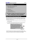
3.1.2 Design Implementation
Basically, the project consists of two parts for implementation which are
design for hardware architecture and design for I/O interface circuit. Thus, this
project was implemented by using the FPGA on the Altera DE1 board. To develop
the hardware programming, the design was written in Verilog HDL (Verilog
Hardware Description Language) coding styles and compiled using Altera Quartus II
software. Therefore, the general implementation steps of the floating point math
hardware module were summarized in Figure 3.1.
32
Part 1: Design for hardware architercture
- All the design were written in Verilog HDL coding styles using Altera
Quartus II software.
- Develop the design for conventional floating algorithms based on single
precision IEEE-754 standard.
- Develop the design for CORDIC algorithm to increase the efficiency to
solve the transcendental functions.
Part 2: Design for I/O interface circuit
- Develop the controller design to interface 4x4 matrix keypad and LCD.
It is writen in Verilog HDL.
- Construct the interface circuit on the donut board by soldering.
- Connect the interface circuit with the Altera DE1 board using through
GPIO ports (40 pins expansion header).
Figure 3.1
General Design Implementation Steps
According to Figure 3.1, the project implementation was started by
developing the conventional floating point algorithm in Verilog HDL to build simple
floating point math module that able to solve for the typical operations which are
addition, subtraction, multiplication and division in IEEE-754 format. Then, the
CORDIC algorithm is further developed to solve some transcendental functions
efficiently such as trigonometry, hyperbolic and exponential.
After the design for hardware architecture is done, the external I/O interface
circuit was designed and the schematic was drawn. Prior to solder the whole circuit
onto the donut board, the design circuit was tested on the breadboard first to ensure
that the circuit is functioning well. Then, the working circuit was soldered careful
onto a piece of donut board. Therefore, after the interface circuit is constructed, the
controllers for interfacing the 4x4 matrix keypad and 16x2 character LCD were
developed using Verilog HDL. It used to interface with an external I/O interface
circuit through 40 pins GPIO port of the Altera DE1 board.
33
3.1.3
Design Testing and Verification
In this stage, the behavioral simulation needs to be performed to test and
verify the functionality of the design through waveform. To do it, specific waveform
simulator software namely Altera-ModelSim is required. Firstly, the project file is
simulated by using the Altera-ModelSim which is invoked from Quartus II. After
that, signal tracing is made to check with the desired functionality and perform
verification. Thus, the verification can be done by comparing the result from the
simulation with the result computed by scientific calculator. If the result is incorrect,
the design stage needs to be turned back to design implementation and then debug
the programming code to find out the error part.
Moreover, to test the functionality of the math module with the interface
circuit, it is required to program onto the Altera DE1 board and then observe the
functionality on the interface circuit. If it is improper or not working, it needs to turn
back to design implementation stage to troubleshoot the problem either from the
programming code or the discontinuity of the soldered circuit. Therefore, this stage
might consume a lot of time in troubleshooting the design errors.
Finally, if all the designs either for the hardware part or interface part are
working fine, the verification was done by comparing the results that output from the
interface circuit with the simulation results. The result should be the same for each
other.
34
3.1.4
Flowchart of the Overall Project Workflow
The summarized workflow of the project is illustrated in the Figure 3.2.
Start
Identify the Problem Statement
Limit the Project Scope
Literature Reviews
Determine the Design Specifications
Implement the designs
Test and verify the results of the designs
Desired
Results?
No
Yes
Analyze and discuss the final results
Done
Figure 3.2 The flowchart of the overall project workflow
CHAPTER 4
PROJECT DESIGN AND ARCHITECTURE
4.1
Basic Floating Point Math Module Design
For this project, there are four basic modules were designed to compute four
typical operations which are addition, subtraction, multiplication and division by
using the conventional algorithm. These modules are complied with IEEE-754 single
precision floating point format.
4.1.1
Floating Point Adder
A simple floating point adder module was designed using Verilog HDL. Thus,
this module is mainly used to compute the addition operation in IEEE-754 single
precision floating point format. The name for this module is fpu_add and its block
diagram is as shown in the Figure 4.1.
op1
op2
32
32
sign
fpu_add
en
rst
8
27
final_exp
final_sum
clk
Figure 4.1
Block diagram of floating point adder (fpu_add)
36
Thus, Table 4.1 describes all the inputs and outputs for this block and brief
description of their functions.
Signal Name
Width
Type
Description
clk
1
Input
System Clock
rst
1
Input
Reset values for initializing
en
1
Input
Enable signal
op1
32
Input
Operand 1 in IEEE-754 format
op2
32
Input
Operand 2 in IEEE-754 format
sign
1
Output
Sign bit for output in IEEE-754 format
final_exp
8
Output
Exponent for output in IEEE-754 format
final_sum
27
Output
Mantissa for output in IEEE-754 format
with 4 extra bits for specific purposes
Table 4.1
I/O interface description for fpu_add
This module is only used to solve the addition operation when either both the
operands have positive or negative sign (same sign). Therefore, if two input operands
have different sign, this module cannot be used but we need to use floating point
subtractor instead for this case.
Basically, the algorithm of this design is similar to the design done by
Mahendra Kumar Soni [12] but the algorithm is modified with some additional steps.
Thus, the algorithm for my design is as shown in the following:
1. Sort the input operands by comparing the values in op1 with op2.
Store the exponent and mantissa of bigger number and smaller number
into two different registers.
2. Determine the exponent different for op1 and op2.
Subtract the exponent of bigger number with smaller number.
3. Expand the mantissa bits for op1 and op2 into 27 bits.
Concatenate an extra bit for leading one (for normalized) or leading zero
(for denormalized) in front of the MSB of mantissa. Then, append one
more zero on the left of it.
Append two bits of zero after the LSB of the mantissa.
37
Resulted mantissa = {1’b0, leading 0/1, mantissa, 2’b00}
4. Pre-align the mantissa of smaller number.
Shift to the right by an amount of bits that same as the exponent different.
5. Add the mantissa of bigger number with the pre-aligned mantissa of smaller
number to get the tentative result.
6. Check whether the mantissa of tentative result is overflow or not.
If overflow occurs, shift right the mantissa and increment the exponent by
1 bit
4.1.2
Floating Point Subtractor
A simple floating point subtractor was designed by using Verilog HDL. Thus,
this module is mainly used to compute the subtraction operation in IEEE-754 single
precision floating point format. The name for this module is fpu_sub and its block
diagram is as shown in the Figure 4.2.
32
op1
32
op2
sign
fpu_sub
addsub
8
final_exp
en
26
rst
final_diff
clk
Figure 4.2
Block diagram of floating point subtractor (fpu_sub)
Thus, Table 4.2 describes all the inputs and outputs for this block and brief
description of their functions.
Signal Name
Width
Type
Description
clk
1
Input
System Clock
rst
1
Input
Reset values for initializing
en
1
Input
Enable signal
38
addsub
1
Input
addsub signal
if addsub = 0, subtraction operation
resulted from the addition of two different
sign numbers.
if addsub = 1, subtraction operation
resulted from the subtraction of two same
sign numbers.
op1
32
Input
Operand 1 in IEEE-754 format
op2
32
Input
Operand 2 in IEEE-754 format
sign
1
Output
Sign bit for output in IEEE-754 format
final_exp
8
Output
Exponent for output in IEEE-754 format
final_diff
26
Output
Mantissa for output in IEEE-754 format
with extra 3 bits for specific purposes
Table 4.2
I/O interface description for fpu_sub
This module is similar to floating point adder where it only used to solve the
subtraction operation when either both the operands have positive or negative sign
(same sign). Therefore, if two input operands have different sign, this module cannot
be used but we need to use floating point adder instead to compute it.
Basically, the algorithm of this design is similar to the design done by
Mahendra Kumar Soni [12] but the algorithm is modified with some additional steps.
Thus, the algorithm for my design is as shown in the following:
1. Sort the input operands by comparing the values in op1 with op2.
Store the exponent and mantissa of bigger number and smaller number
into two different registers.
2. Determine the exponent different for op1 and op2.
Subtract the exponent of bigger number with smaller number.
3. Expand the mantissa bits for op1 and op2 into 26 bits.
Concatenate an extra bit for leading one (for normalized) or leading zero
(for denormalized) in left of the MSB of the mantissa.
Append two bits of zero in right of the LSB of the mantissa.
Resulted mantissa = {leading 0/1, mantissa, 2’b00}
39
4. Pre-align the mantissa of smaller number.
Shift to the right by an amount of bits that same as the exponent different.
5. Subtract the mantissa of bigger number with the pre-aligned mantissa of smaller
number to get the tentative result.
6. Count the number of leading zero in the mantissa of tentative result.
If the number of leading zero > the exponent of larger number, shift left
the mantissa of tentative result by 1 bit and set the exponent for the result
to 0.
If the number of leading zero < the exponent of larger number, shift left
the mantissa and decrement the exponent by an amount of bits which
same as the number of leading zero.
4.1.3
Floating Point Multiplier
A simple floating point multiplier is designed by using Verilog HDL. Thus,
this module is mainly used to compute the multiplication operation in IEEE-754
single precision floating point. The name for this module is fpu_mul and its block
diagram is as shown in the Figure 4.3.
op1
op2
32
32
sign
fpu_mul
en
9
rst
27
final_exp
final_prod
clk
Figure 4.3
Block diagram of floating point multiplier (fpu_mul)
Thus, Table 4.3 describes all the inputs and outputs for this block and brief
description of their functions.
40
Signal Name
Width
Type
Description
clk
1
Input
System Clock
rst
1
Input
Reset values for initializing
en
1
Input
Enable signal
op1
32
Input
Operand 1 in IEEE-754 format
op2
32
Input
Operand 2 in IEEE-754 format
sign
1
Output
Sign bit for output in IEEE-754 format
final_exp
9
Output
Exponent for output in IEEE-754 format
with an extra bit for specific purpose
final_prod
27
Output
Mantissa for output in IEEE-754 format
with extra 4 bits for specific purposes
Table 4.3
I/O interface description for fpu_mul
Basically, the algorithm of this design is similar to the design done by
Mahendra Kumar Soni [4] but the algorithm is modified with some additional steps.
Thus, the algorithm for my design is as shown in the following:
1. Determine the value of exponent.
Simply add the exponents from two operands and then subtract by 127 to
become biased exponent.
2. Expand the mantissa for both operands to 24 bits.
Append a leading zero or leading one bit on the left of mantissa.
3. Multiplication
Perform the multiplication between the mantissa from two operands after
the range is expanded to 24 bits. It will results in 48 bits result after
multiplication.
Sign is determined by exclusive-OR the sign of both operands
4. Normalization
Normalize the value by checking the number of leading zero of the
tentative result and then shift the result to left and decrement exponent by
the an amount same as the number of leading zeros. However, if the
tentative result overflows, shift right the mantissa and increment the
exponent by 1 bit.
41
4.1.4
Floating Point Divider
A simple floating point divider is designed by using Verilog HDL. Thus, this
module is mainly used to compute the division operation in IEEE-754 single
precision floating point. The name for this module is fpu_div and its block diagram is
as shown in the Figure 4.4.
32
op1
32
op2
sign
fpu_div
en
9
rst
27
exp_out
frac_out
clk
Figure 4.4
Block diagram of floating point divider (fpu_div)
Thus, Table 4.4 describes all the inputs and outputs for this block and brief
description of their functions.
Signal Name
Width
Type
Description
clk
1
Input
System Clock
rst
1
Input
Reset values for initializing
en
1
Input
Enable signal
op1
32
Input
Operand 1 in IEEE-754 format
op2
32
Input
Operand 2 in IEEE-754 format
sign
1
Output
Sign bit for output in IEEE-754 format
exp_out
9
Output
Exponent for output in IEEE-754 format
frac_out
27
Output
Mantissa for output in IEEE-754 format
with extra 4 bits for specific purposes
Table 4.4
I/O interface description for fpu_div
Basically, the division is performed by several shifting and subtracting
operations. It is similar with the hand calculation method for division. For IEEE-754
42
format, it has 24 bits mantissa if include the hidden bit. Therefore, the shift and
subtract operation need to be performed with 24 iterations to compute the value of
result bit by bit. Thus, the algorithm for my design is as shown in the following:
1. Determine the number of leading zeroes for both operands
Count the number of leading zeros for the mantissa of both operands and
store them into registers.
2. Shifting left
Shift left the mantissas for both operands by corresponding number of
leading zeroes.
3. Division
Initialize and start the counter for iteration. Create a counter that count
from 24 and decrement until 0 to indicate the start and end of the
operation.
Determine the value of result bit by bit. It can be done by shift and
subtract when the counter is valid.
The sign of the result is determined by exclusive-OR the sign for both
operands.
The resulted exponent of is calculated based on the following equation:
Resulted E = exponent of op1 – exponent of op2 + 127 – number of
leading zero of op1 + number of leading zero of op2
4. Normalization
Normalize the value by checking the number of leading zero of the
tentative result and then shift the result to left and decrement exponent by
the an amount same as the number of leading zeros. However, if the
tentative result overflows, shift right the mantissa and increment the
exponent by 1 bit.
4.1.5
Rounding Logic
For the above modules, the output is not yet rounded and concatenated to be a
32 bits IEEE-754 format. Therefore, each of the outputs from the above design
43
should be connected to a rounding logic to round the result and then concatenate the
sign, exponent and mantissa to be a 32 bits IEEE-754 format. In my design, the
round to nearest mode is used for rounding the result.
4.2
Efficient Floating Point Math Module
For this project, an efficient hardware algorithm, namely CORDIC algorithm
which proposed by Volder [7] is also used to realize solution for trigonometry and
hyperbolic functions. Based on my findings, this algorithm is simple and inexpensive
for hardware implementation as only shift registers, adders and ROM. Therefore,
there are two modules were designed based on CORDIC algorithm to solve for the
trigonometry and hyperbolic with exponential functions. Meanwhile, this
computation for the design is made in fixed-point format but the result is converted
back to IEEE-754 single precision format to be the output of the floating point math
module.
4.2.1 The Architecture of CORDIC Algorithm
Generally, the architecture of CORDIC algorithm is illustrated in Figure 4.5.
Figure 4.5
Basic Architecture of CORDIC Algorithm
44
4.2.2
Trigonometric CORDIC Module
From Table 2.2, to find the values of sine and cosine, the CORDIC algorithm
need to be implemented in circular rotational mode. Thus, it performs a rotation with
the help of a series of incremental rotation angles and then perform shift and add or
subtract operations with a limit number of iterations. In my design, the angle is
rotated by 15 times (iteration number, i =15). Table 4.5 shows the look-up table for
rotational angles from 0 to 15 iterations which used to evaluate the trigonometry
functions.
Rotation angle, ϕ = tan-1 (2-i)
tan ϕ = 2-i
0
45.00000000
1
1
26.56505118
1/2
2
14.03624347
1/4
3
7.12501635
1/8
4
3.57633437
1/16
5
1.78991061
1/32
6
0.89517371
1/64
7
0.44761417
1/128
8
0.22381050
1/256
9
0.11190568
1/512
10
0.02797645
1/1024
11
0.01398823
1/2048
12
0.00699411
1/4096
13
0.00349706
1/8192
14
0.00174853
1/16384
15
0.00087426
1/32768
Iteration
number, i
Table 4.5 Look-up Table for Rotational Angles from 0 to 15 iterations
(CORDIC_Circular)
Thus, the name of this design is CORDIC_Circular and the block diagram is
shown in Figure 4.5.
45
angle
32
cos_eff
CORDIC
_Circular
sin_eff
clk
Figure 4.6
Block diagram of CORDIC_Circular
Then, Table 4.6 describes all the inputs and outputs for this block and brief
description of their functions.
Signal Name
Width
Type
Description
clk
1
Input
System Clock
angle
32
Input
Input angle in Q-format (Q0.32)
*Notes: Conversion equation:
Desired Angle in degree/360*232
cos_eff
17
Output
Output value for cosine in Q-format
(Q2.15)
*Notes: Conversion equation: Value*215
sin_eff
17
Output
Output value for sine in Q-format
(Q2.15)
*Notes: Conversion equation: Value*215
Table 4.6
I/O Interface description for CORDIC_Circular
Since the data is in Q-format, all the data inside this design as well as the data of
look-up table of rotational angles need to be converted to this format. After that, the
algorithm to implement this module is shown in the following:
1. Set two initial values for Xin and Yin.
Xin and Yin is the initial values of cos_eff and sin_eff. These values will
become the answer for cos_eff and sin_eff after 15 iterations.
Set Xin = 0.607252935 = 16’b0100110110111010 (in Q1.15) format.
Notes that the conversion equation = Value*215
46
Set Yin = 0 = 16’b0000000000000000 (in Q1.15) format
2. Construct look-up table for rotational angle from 0 to 15 iterations.
Convert all the values in Table 4.5 to Q0.32 format and store into the
atan_table RAM.
Conversion equation = rotational angles/360*232
3. Set the value of shifted X (X_shr) and shifted Y (Y_shr).
Set X_shr and Y_shr by right shifting by i (iteration number) places.
4. Determine the rotation direction and the values of X, Y and Angle for the next
iteration.
If Angle >= 0, rotate the angle in anti-clockwise direction for the next
iteration. Thus, set X to value of X – Y_shr, set Y to value of Y + X_shr
and set Angle to value of Angle – atan_table[i] in order to update the
values for X, Y and Angle.
If Angle < 0, rotate the angle in clockwise direction for the next iteration.
Thus, set X to value of X + Y_sh, set Y to value of Y – X_sh, set Angle to
value of Angle + atan_table[i] in order to update the values for X, Y, and
Angle.
4.2.3
Hyperbolic CORDIC Module
From Table 2.2, to find the values of sinh, cosh and exp, the CORDIC
algorithm need to be implemented in hyperbolic rotational mode. Similar to the
trigonometry CORDIC module, a look-up table needs to be constructed. Thus, Table
4.7 shows the look-up table for rotational angles from 1 to 15 iterations which used
to evaluate the hyperbolic functions.
Rotation angle, ϕ = tanh-1 (2-i)
tanh ϕ = 2-i
1
0.5493061443
1/2
2
0.2554128119
1/4
3
0.1256572141
1/8
4
0.0625815715
1/16
Iteration
number, i
47
5
0.0312601785
1/32
6
0.0156262718
1/64
7
0.0078126580
1/128
8
0.0039062690
1/256
9
0.0019531270
1/512
10
0.0009765620
1/1024
11
0.0004882810
1/2048
12
0.0002441400
1/4096
13
0.0001220700
1/8192
14
0.0000610350
1/16384
15
0.0000305170
1/32768
Table 4.7
Look-up Table for Rotational Angles from 1 to 15 iterations
(CORDIC_Hyperbolic)
Thus, the name of this design is CORDIC_Hyperbolic and the block diagram
is shown in Figure 4.6.
angle
32
cosh_eff
CORDIC_
Hyperbolic
sinh_eff
clk
Figure 4.7
Block diagram of CORDIC_Hyperbolic
Then, Table 4.8 describes all the inputs and outputs for this block and brief
description of their functions.
Signal Name
Width
Type
Description
clk
1
Input
System Clock
hyper_in
32
Input
Input angle in Q-format (Q2.30)
*Notes: Conversion equation:
Desired Hyperbolic Angle*230
48
cosh_eff
17
Output
Output value for cosine in Q-format
(Q2.15)
*Notes: Conversion equation: Value*215
sinh_eff
17
Output
Output value for sine in Q-format (Q2.15)
*Notes: Conversion equation: Value*215
Table 4.8
I/O Interface description for CORDIC_Hyperbolic
Since the data is in Q-format, all the data inside this design as well as the data of
look-up table of rotational angles need to be converted to this format. After that, the
algorithm to implement this module is shown in the following:
1. Set two initial values for Xin and Yin.
Xin and Yin is the initial values of cosh_eff and sinh_eff. These values
will become the answer for cosh_eff and sinh_eff after 15 iterations.
Set Xin = 1.20753406= 16'b1001101010010000 (in Q1.15) format. Notes
that the conversion equation = Value*215
Set Yin = 0 = 16’b0000000000000000 (in Q1.15) format
2. Construct look-up table for rotational angle from 1 to 15 iterations.
Convert all the values in Table 4.8 to Q2.30 format and store into the
atan_table RAM.
Conversion equation = rotational angles*230
3. Set the value of shifted X (X_shr) and shifted Y (Y_shr).
Set X_shr and Y_shr by right shifting by i (iteration number) places.
4. Determine the rotation direction and the values of X, Y and Angle for the next
iteration.
If Angle >= 0, rotate the angle in anti-clockwise direction for the next
iteration. Thus, set X to value of X + Y_shr, set Y to value of Y + X_shr
and set Angle to value of Angle – atan_table[i] in order to update the
values for X, Y and Angle.
If Angle < 0, rotate the angle in clockwise direction for the next iteration.
Thus, set X to value of X - Y_sh, set Y to value of Y – X_sh, set Angle to
value of Angle + atan_table[i] in order to update the values for X, Y, and
Angle.
49
4.2.4
Q-format to IEEE-754 format Converter
Since the outputs of the module of CORDIC module are in Q-format (Q2.15),
it needs to be converted to the IEEE-754 single precision floating-point format after
the result is obtained. After that, the output in IEEE-754 format can be used to
perform floating addition, subtraction, multiplication or subtraction. Thus, by this,
the value for tangent, hyperbolic tangent and exponent can be computed by the
following mathematical equations:
The algorithm to convert from Q2.15 format to 32-bits single precision
format is simple. Thus, the value for sign, exponent and mantissas need to be
determined shown below, assuming that Q-data is the data from Q2.15 format, then
1. Sign = Qdata [16]
2. If sign = 0, Mantissa = {Qdata [15:0], {8{1’b0}}
If sign = 1, Mantissa = {~Qdata[15:0] + 1, {8{1’b0}}
3. Exponent = 127 – number of leading zeroes in Mantissa
4.3
External Interface Circuit
In order to develop I/O interface to test the functionality of my design, a 4x4
matrix keypad and 16x2 character LCD were used to construct an external interface
circuit on a donut board by soldering. Thus, Figure 4.8 shows the schematic of the
completed interface circuit.
50
Figure 4.8
The schematic diagram of external interface circuit
Thus, the pin assignments on the Altera DE1 board for the design are shown in Table
4.9.
Pins from
Pins for FPGA (DE1
Description
interface circuit
board side)
VCC
3.3VCC
3.3V Power Supply
GND
GND
Ground
RS
PIN_B13 (GPIO_0 pin 1)
LCD Register Select
R/W
PIN_B14 (GPIO_0 pin 3)
LCD Read/Write
E
PIN_B15 (GPIO_0 pin 5)
LCD Enable
DB0
PIN_B16 (GPIO_0 pin 7)
LCD Data bit 0
51
DB1
PIN_B17 (GPIO_0 pin 9)
LCD Data bit 1
DB2
PIN_B18 (GPIO_0 pin 11)
LCD Data bit 2
DB3
PIN_B19 (GPIO_0 pin 13)
LCD Data bit 3
DB4
PIN_B20 (GPIO_0 pin 15)
LCD Data bit 4
DB5
PIN_C21 (GPIO_0 pin 17)
LCD Data bit 5
DB6
PIN_D21 (GPIO_0 pin 18)
LCD Data bit 6
DB7
PIN_B21 (GPIO_0 pin 20)
LCD Data bit 7
Port
PIN_G21 (GPIO_0 pin 24)
LCD backlight control
Input 1 (C1)
PIN_K20(GPIO_0 pin 33)
Keypad Column 1
Input 2 (C2)
PIN_L19 (GPIO_0 pin 34)
Keypad Column 2
Input 3 (C3)
PIN_J19 (GPIO_0 pin 30)
Keypad Column 3
Input 4 (C4)
PIN_K21 (GPIO_0 pin 28)
Keypad Column 4
Output 1 (R1)
PIN_A18 (GPIO_0 pin 10)
Keypad Row 1
Output 2 (R2)
PIN_A16 (GPIO_0 pin 6)
Keypad Row 2
Output 3 (R3)
PIN_A14 (GPIO_0 pin 2)
Keypad Row 3
Output 4 (R4)
PIN_A13 (GPIO_0 pin 0)
Keypad Row 4
-
PIN_L1 (Clock_50MHz)
Internal Clock Source
(50MHz)
-
PIN_R22 (Key_0)
Table 4.9
4.3.1
Reset Button
Pin assignments on Altera DE1 Board
Matrix Keypad Scanner
In order to determine which buttons on the matrix keypad is pressed, a
keypad scanner has to be designed to scan the state of all buttons row by row and
column by column every small time interval. In my design, the keypad is scanned by
switching the number of column at each 1ms of time interval. At the same time, it
will check the state of the each row within 1ms. Therefore, the output gives a specific
data to indicate which button is pressed. Thus, this scanner is very useful because it
can send specific data to the system when any button was pressed. The block
diagram to design a working keypad scanner is shown in Figure 4.9.
52
1ms Counter
col [3:0]
Keypad Scan
row [3:0]
Check for
Button Pressed
data [3:0]
Figure 4.9
4.3.2
Block diagram of Keypad Scanner
De-bouncer
Initially, some testing are done by sending the keypad data to the system by
pressing button and then display a character on LCD based on the received data.
However, the LCD does not properly receive the data for each time. Sometime, the
data is sent more than one time although it is one time pressed and sometime even
not received at all or received incorrect data. It seems like the system is unstable.
Thus, the problem for this issue was investigated. Finally, the problem was found
where it is due to the debouncing glitch of the push buttons [14]. Therefore, a debouncer has to be designed to filter out the glitches associated with switch transitions.
This design is based on FSM approach and uses a free-running 10 ms timer.
The timer generate a one-clock-cycle enable tick every 10ms and then use the FSM
approach to keep track of whether the input is stabilized. However, the FSM ignores
the short bounces and changes the value of the debounced output only. Therefore, the
state diagram to construct the FSM is shown in Figure 4.10.
53
Figure 4.10
4.3.3
State diagram of De-bouncer FSM [14]
LCD Controller
In order to display certain string or character on the LCD, a controller is
needed to control the LCD operations. The design is also built using FSM approach.
Thus, the RS is set to 0 and the sending of some initialization command is started.
Thus, in my design, some initialization command was sent and its descriptions are
shown in Table 4.10.
Command data (in
Descriptions
binary)
00111000
Function Set for 8 bits data transfer and 2 line display
00001111
Display On, without cursor
00000001
Clear Screen
54
00000110
Entry mode set, increment cursor automatically after
each character was displayed
00000010
Table 4.10
Return the cursor to home address
Initialization Command data and description
According to the LCD operating theory, to successful sent a data to LCD, a
pulse needs to be sent to the enable pin after the data is sent and then delay for a
certain amount of time for the LCD to receive and process the data. Meanwhile,
different type of command data might need different interval of the delay.
Similarly, to display a character on the LCD, the RS is set to 1 and the ASCII
code for specific character is sent. After that, a pulse needs to be sent to enable pin
and then delay for an amount of time.
4.4
Overall Design
Anyway, although several kinds of floating point math hardware modules
were successfully designed, but only the CORDIC module was chosen to be
implemented on the interface circuit. This is because the limited hardware resources
in Altera DE1 board is limited and might not able to cover all-in-one design. Thus,
some useful math modules have to be selected for interfacing. Therefore, CORDIC
module can be considered a very useful module since it can solve for elementary
functions such as trigonometry and hyperbolic which is applicable in the field of
digital signal processing [12].
Therefore, all the related I/O interface module are integrated with the
CORDIC trigonometry and hyperbolic modules to build a simple generator that can
generate an answer for cos, sin, cosh, sinh and also exponent and then display on the
LCD. Thus, the design architecture for overall design is shown in Figure 4.11.
55
Figure 4.11
Design Architecture of the overall design
From Figure 4.11, the design is basically controlled by a controller based on
FSM. The outputs of the CORDIC module, keypad scanner, de-bouncer, and
multiple ROM are act as the input of the controller. Then, the LCD_RW,
LCD_BLON, LCD_DATA, LCD_EN, LCD_RS are the output of the controller
which connected to the LCD for display the messages. Apart from that, the controller
also sent the address to the ROM to access its memory. Besides that, an enable signal
for de-bouncer is also controlled by the controller. Meanwhile, for the input, the
system is actually retrieving the input from user based on the keypad button that has
been pressed and then scan it to generate an appropriate signal for the controller to
process.
CHAPTER 5
PROJECT MANAGEMENT
A project represents a collection of tasks aimed toward a single set of
objectives, culminating in a definable end point and having a finite life span and
budget. Normally, a project is a one-of-a-kind activity which aimed to produce some
product or outcome that has never existed before. Therefore, there are two essential
considerations in project management which are time or project schedule and cost.
5.1.1
Project Schedule
First of all, planning of a project’s progress is essential, so all the important
works were scheduled into Gantt chart for FYP1 and FYP2 before this project is
started as shown in Figure 5.1 and Figure 5.2.
Figure 5.1
Gantt Chart of FYP1
57
Figure 5.2
5.1.2
Gantt Chart of FYP2
Project Cost
Basically, projects have a budget and limited resources. Thus, the budget for
this project is RM200 and resources are limited for the hardware logic elements on
Altera DE1 board. Therefore, this project was developed in two parts. The first part
is about the programming and the second part is the implementation. Thus, for the
first part, the required hardware resources need to be considered for the design.
Meanwhile, for the second part, the required cost to implement the design with I/O
interface circuit on the Altera DE1 board need to be calculated. Thus, an Altera DE1
board was borrowed from Dreamcatcher by participating in the Innovate Competition
2013. Then, all the electronic components and material needed to construct an I/O
interface circuit with the prices are listed down as shown in Table 5.1. All of these
components are available in Cytron Technologies Sdn. Bhd..
No.
Component Names
Quantity
Unit Price Amount
(Set)
(RM)
(RM)
1.
Female to Female Jumper Wires
3
4.50
13.50
2.
Resistor 0.25W 5% 1K
4
0.05
0.20
3.
Resistor 0.25W 5% 10K
2
0.05
0.10
4.
Preset 5K
1
0.50
0.50
5.
Transistor 2N2222
1
0.40
0.40
6.
Straight Pin Header (Male) 1x40
1
0.60
0.60
Ways
58
7.
LCD (16x2)
1
18.00
18.00
8.
Keypad 4x4
1
25.00
25.00
9.
Donut Board (Fiber) 1mm
1
8.00
8.00
10x22cm
10.
Rainbow Cable 20 Ways (meter)
1
8.00
8.00
10.
Atten 830L Digital Multimeter
1
28.00
28.00
11.
Soldering Iron (25W)
1
10.00
10.00
12.
Solder Stand (ZD-10)
1
8.00
8.00
13.
Solder Lead 1.0mm (250gm)
1
29.50
29.50
14.
Pro’skit Desoldering Pump
1
16.00
16.00
Total:
165.50
Table 5.1
List of Components and Materials needed
Thus, the total amount of cost is RM165.60 which is within the budget.
Therefore, the cost problem need not be worried and then the implementation works
can be focused.
CHAPTER 6
RESULTS AND ANALYSIS
In this chapter, all the results that have been done in this project are verified
and analyzed. Thus, the result from the LCD is verified by comparing to the
simulation result. In addition, the performance of the design is also investigated
based on the clock cycle or latency needed for computation done.
6.1
Simulation Results
The design units explained in the previous chapter has been coded in Verilog
HDL and simulated using ModelSim-Altera software which invoked from the
Quartus II software. Thus, the output waveforms for each floating point math
hardware module were shown in the following subsection. In addition, the output is
also compared with the actual result that calculated by scientific calculator.
6.1.1
Floating Point Adder
The output waveform generated by fpu_add is shown in Figure 6.1. It
performs the floating point addition between op1 and op2 and gives the result in
add_out. All the data are represented in IEEE-754 single precision floating point
format. This design requires 12 clock cycles to complete the addition operation as
shown in Figure 6.1. The output will be zero before the computation is done.
60
Figure 6.1
Simulation result of fpu_add
Thus, the detailed description of the given inputs and output generated is
shown in Table 6.1.
Input operands
op1 (in IEEE-754 binary) = 0 10000011 01010001101010000111000
Decimal value =
= 21.1036224
op2 (in IEEE-754 binary) = 0 10000010 11011111111011100111001
Decimal value =
= 14.9978568
Output operands
add_out (in IEEE-754 binary) = 0 10000100 00100000110011111101010
Decimal value =
Actual value (by scientific calculator) = 36.1014792
Table 6.1
= 36.1014784
The detailed description of input and output operands from the
output waveform of fpu_add
Based on the result in Table 6.1, the output result from the fpu_add is closely
the same as the result calculated by scientific calculator. The precision of up to 5
decimal places was achieved if compare these two results. Thus, this module is
working as desired and the result is verified.
6.1.2
Floating Point Subtractor
The output waveform generated by fpu_sub is shown in Figure 6.2. It
performs the floating point subtraction between op1 and op2 and gives the result in
sub_out. All the data are represented in IEEE-754 single precision floating point
61
format. Similar to fpu_add, this design also requires 12 clock cycles for computation
as shown in Figure 6.2. The output will be zero before the computation is done.
Figure 6.2 Simulation Result of fpu_sub
Thus, the detailed description of the given inputs and output generated is
shown in Table 6.2.
Input operands
op1 (in IEEE-754 binary) = 0 10000011 01010001101010000111000
Decimal value =
= 21.1036224
op2 (in IEEE-754 binary) = 0 10000010 11011111111011100111001
Decimal value =
= 14.9978568
Output operands
sub_out (in IEEE-754 binary) = 0 10000001 10000110110001001101110
Decimal value =
Actual value (by scientific calculator) = 6.1057656
Table 6.2
= 6.1057652
The detailed description of input and output operands from the
output waveform of fpu_sub
Based on the result in Table 6.2, the output result from the fpu_sub is closely
the same as the result calculated by scientific calculator. The precision of up to 5
decimal places was achieved if compare these two results. Thus, this module is
working as desired and the result is verified.
62
6.1.3
Floating Point Multiplier
The output waveform generated by fpu_mul is shown in Figure 6.3. It
performs the floating point multiplication between op1 and op2 and gives the result
in mul_out. All the data are represented in IEEE-754 single precision floating point
format. Meanwhile, this design requires 14 clock cycles to complete the
multiplication operation as shown in Figure 6.3. The output will be zero before the
computation is done.
Figure 6.3
Simulation Result of Floating Point Multiplier
Thus, the detailed description of the given inputs and output generated is
shown in Table 6.3.
Input operands
op1 (in IEEE-754 binary) = 0 10000110 00100011001000101011101
Decimal value =
= 145.5678208
op2 (in IEEE-754 binary) = 0 10000011 01111001000011000000000
Decimal value =
= 23.5654304
Output operands
mul_out (in IEEE-754 binary) = 0 100010101 0101100110010111100101
Decimal value =
Actual value (by scientific calculator) = 3430.36835
Table 6.3
= 3430.368461
The detailed description of input and output operands from the
output waveform of fpu_mul
Based on the result in Table 6.3, the output result from the fpu_mul is closely
the same as the result calculated by scientific calculator. The precision of up to 3
63
decimal places was achieved if compare these two results. Thus, this module is
working as desired and the result is verified.
6.1.4
Floating Point Divider
The output waveform generated by fpu_div is shown in Figure 6.4. It
performs the floating point division between op1 and op2 and gives the result in
div_out. All the data are represented in IEEE-754 single precision floating point
format. However, this design requires about 40 clock cycles to complete the division
operation as shown in Figure 6.4 due to iteration calculations in the algorithm to
compute the quotient. The output will be zero before the computation is done.
Figure 6.4
Simulation Result of Floating Point Divider
Thus, the detailed description of the given inputs and output generated is
shown in Table 6.4.
Input operands
op1 (in IEEE-754 binary) = 0 10000110 00100011001000101011101
Decimal value =
= 145.5678208
op2 (in IEEE-754 binary) = 0 10000011 01111001000011000000000
Decimal value =
= 23.5654304
Output operands
div_out (in IEEE-754 binary) = 0 10000001 10001011010101101101111
Decimal value =
Actual value (by scientific calculator) = 6.177176412
Table 6.4
= 6.1771768
The detailed description of input and output operands from the
output waveform of fpu_div
64
Based on the result in Table 6.4, the output result from the fpu_div is closely
the same as the result calculated by scientific calculator. The precision of up to 6
decimal places was achieved if compare these two results. Thus, this module is
working as desired and the result is verified.
6.1.5
CORDIC Module
This module combines the trigonometric CORDIC, hyperbolic CORDIC and
Q-format to IEEE-754 converter. Therefore, it can compute the result for cos, sin,
cosh, sinh and exp. The output waveform is shown in Figure 6.5.
Figure 6.5
Simulation result of CORDIC module
Figure 6.5 shows the output waveform generated by CORDIC module. It
performs the CORDIC iteration calculations and gives the results of cos, sin, cosh,
sinh and exp. The input data are represented in Q-format and the output data are
represented in IEEE-754 single precision floating point format. Meanwhile, this
design requires about 18 clock cycles for computation as shown in Figure 6.5 due to
iteration calculations in the CORDIC algorithm.
Thus, the detailed description of the given inputs and output generated is
shown in Table 6.5.
Input operands
angle (in Q0.32 unsigned binary) = 111010101 01010101010101010101011
Decimal value =
65
hyper_in (in Q2.30 unsigned binary)= 00100000000000000000000000000000
Decimal value =
Output operands
cos (in IEEE-754 binary) = 0 01111110 10111011011011000000000
Decimal value =
Actual value (by scientific calculator) = 0.8660254038
= 0.86605835
sin (in IEEE-754 binary) = 1 01111110 00000000000001000000000
Decimal value =
Actual value (by scientific calculator) = -0.5
= -0.5000305
cosh (in IEEE-754 binary) = 0 01111111 00100001001111100000000
Decimal value =
Actual value (by scientific calculator) = 1.127625965
= 1.1298523
sinh (in IEEE-754 binary) = 0 01111110 00001011010100000000000
Decimal value =
Actual value (by scientific calculator) = 0.5210953055
= 0.5220947
exp (in IEEE-754 binary) = 0 01111111 10100110111001100000000
Decimal value =
Actual value (by scientific calculator) = 1.648721271
Table 6.5
= 1.651947
The detailed description of input and output operands from the
output waveform of CORDIC module
Based on the results in Table 6.5, the output results for cos and sin were
closely the same with the result calculated from scientific calculator. The precision
up to 4 decimal places was achieved if compare these two sets of result. However,
the output results for cosh, sinh and exp did not achieve high precision from the
actual value. They have only 1-2 decimal places precision. This is due to the low
precision of the number representation format that has been used for the hyperbolic
operation which is Q2.30 format. In order to achieve higher precision, the hyperbolic
CORDIC module needs to be designed using the higher precision floating point
format such as IEEE-754 format to perform the computation. Anyway, although only
low precision achieved for some parts of the design but the design is generally works
and give the acceptable results.
66
6.2
Interface Circuit Results from LCD display
Based on the CORDIC module, the design is further interfaced with an I/O
interface circuit to display the result so that the results can be checked more easily
without tracing from the simulation waveform. Thus, Figure 6.6 shows the completed
I/O interface circuit that has been done on the donut board.
Figure 6.6
I/O interface circuit on donut board with working LCD display
By using this module, the results are displayed in hexadecimal form that
converted from the binary value of 32-bits single precision IEEE-754 floating point
format. Thus, by introducing some inputs from the CORDIC module as discussed in
previous section where angle = 330o and hyper_in = 0.5, the outputs on LCD displays
for cos, sin, cosh, sinh and exp were recorded as shown in Table 6.6.
Functions
Outputs on LCD displays (in HEX)
cos
0x3F5DB600
sin
0xBF000200
cosh
0x3F909F00
sinh
0x3F05A800
exp
0x3FD37300
Table 6.6
Results collected from LCD display outputs
Based on the results on Table 6.6, since the values that displayed on the LCD
are totally the same with the simulation values, it means that the interface circuit is
working and the results were verified.
.
CHAPTER 7
CONCLUSION AND FUTURE WORKS
In this chapter, the conclusion had been carried out to conclude the all the
results of floating point math module. Besides that, the future work of this project
also been stated for the further improvement of this project.
7.1
Conclusion
As concluded from the simulation results, the design for floating point adder,
subtractor, multiplier and divider are working and their precision of the results are up
to 4 to 6 decimal places. This achieved by using IEEE-754 single precision floating
point. Meanwhile, for CORDIC module, it combines the trigonometric CORDIC,
hyperbolic CORDIC module and binary to IEEE-754 converter. The computation
speed is increased by using the fixed-point format but the precision of the results are
eventually become low. Therefore, it shows that there is a trade-off among IEEE-754
format and fixed-point format where the IEEE-754 format can give the higher
precision result but it needs more time to process, meanwhile the fixed-point format
can shorten the time to process but it results in lower precision.
Therefore, both of the IEEE-754 format and fixed-point format can be used to
compute floating point arithmetic but the analysis upon the precision and speed
requirements of the design should be made to decide which the best choice is. As an
example, for the FPU, it usually requires high precision computation to avoid error or
68
crash on the computers. For this case, the IEEE-754 format is the better floating point
representation to be used in the design.
Apart from that, based on the results obtained from the LCD display of the
interface circuit, it shows the same results as obtained from the simulated results but
the number was converted to hexadecimal form due to insufficient spaces on LCD to
display the 32 bits binary number in single line. Thus, the numbers that are displayed
on LCD were shorter and easier to read. So, this circuit can be used to test the
functionality of the design without referring to the simulation waveform.
In a nutshell, floating point math hardware modules are successfully designed
and implemented based on conventional floating point algorithm and CORDIC
algorithm to solve addition, subtraction, multiplication, division, trigonometric,
hyperbolic and exponential with an acceptable precision. Besides that, a simple
working I/O interface circuit that can interface with the CORDIC module on Altera
DE1 board is also successfully built.
7.2
Future Works
In this project, the simple architecture has been used to code the design
without optimization. Hence, some advance techniques such as loop unrolling,
chaining and multicycling can be used to optimize the area and performance of the
design.
Apart from that, the precision of the floating point number can be enhanced
by using double precision (64 bits) or quad precision (128 bits) of IEEE-754 format
instead of using single precision IEEE-754 format.
Furthermore, the design can be further implemented by using the NIOS II
processor and integrate the hardware and software design to build up a marketable
embedded system.
69
REFERENCES
[1] Lipsa S. and Ruby D. (2012). An Efficient IEEE 754 Compliant Floating Point
Unit Using Verilog. Degree Thesis. India: Department of Computer Science and
Engineering, National Institute of Technology Rourkela.
[2] Ridhi S. (2010). Design and Implementation of Low power High Speed Floating
Point Adder and Multiplier. Master Thesis. India: Department of Electronics and
Communication Engineering, Thapar University.
[3] B. Sreenivasa, J.E.N.Abhilash, G.Rajesh Kumar (2012). Design and
Implementation of Floating Point Multiplier for Better Timing Performance.
International Journal of Advanceed Research in Computer Science & Technology
(IJRCET), Vol. 1, Issue 7, September 2012.
[4] Mahendra K. S. (2009). FPGA Implementation of IEEE 754 Standard Based
Arithmetic Unit for Floating Point Numbers. Master Thesis. India: Department of
Electronics and Communication Engineering, Thapar University.
[5] Aziz I. (2012). Binary Floating Point Fused Multiply Add Unit. Degree Thesis.
Egypt: Falculty of Engineering, Cairo University Giza.
[6] J. E. Volder (1959). The CORDIC trigonometric computing technique. IRE Trans.
Electronic Computers, vol. EC-8, no. 3, pp. 330-334, Sept. 1959.
[7] J. S. Walther (1971). A unified algorithm for elementary functions. AFIPS Spring
Joint Computer Conference, vol. 38, pp 379-85, 1971.
[8] Yi-Jun D. and Zhuo B. (2011). CORDIC algorithm based on FPGA. Journal of
Shanghai University, vol. 15, issues 4, pp. 304-309, Aug 2011.
[9] Vikas S. (2009). FPGA Implementation of EEAS CORDIC Based Sine and
Cosine Generator. Master Thesis. India: Department of Electronics and
Communication Engineering, Thapar University.
70
[10]
Rohit K. J. (2011). Design and FPGA Implementation of CORDIC-based 8-
pint ID DCT Processor. Degree Thesis. India: Department of Electronics and
Communication Engineering, National Institure of Technology Rourkela.
[11]
Boudabous A., Ghozzi F., Kharrat M.W., Masmoudi N. (2004).
Implementation of Hyperbolic Functions Using CORDIC Algorithm. The 16th
International Conference on, pp.738-741, 6-8 Dec. 2004.
[12]
Shrugal V., Nisha S. and Richa U. (2013). Hardware Implementation of
Hyperbolic Tan Using Cordic On FPGA. International Journal of Engineering
Research and Applications (IJERA), Vol. 3, Issue 2, pp696-699, March-April
2013.
[13]
Erick L. (2007). Fixed-Point Representation & Fractional Math. Oberstar
Consulting. [online] Available:
http://www.superkits.net/whitepapers/Fixed%20Point%20Representation%20&%
20Fractional%20Math.pdf
[14]
Pong P. (2008). FPGA Prototyping by Verilog Examples. New Jersey: A John
Wiley & Sons, Inc., Publication.
[15]
Wayne W. (2004). FPGA-Based System Design. New Jersey: Prentice Hall.
[16]
ALTERA (2007). Cyclone II Architecture. Altera Corporation, retrieved from
official website: www.altera.com.
[17]
ALTERA (2012). Altera’s User-Customizable ARM-Based SoC FPGAs.
Altera Corporation, retrieved from official website: www.altera.com.
[18]
ALTERA and Terasic. DE1 Development and Education Board User Manual.
Retrieved from Terasic Official Website: www.terasic.com
[19]
Cytron Technologies. 4x4 Keypad User’s Manual. Retrieved from Cytron
product page: http://www.cytron.com.my/viewProduct.php?pcode=SWKEYPAD-4X4&name=Keypad%204x4
[20]
Julyan I. (1997). How to use Intelligent L.C.D.s. Part One. Wimborne
Pulishing Ltd, publishers of Everyday Practical Electronics Magazine. [online]
Available: http://www.wizard.org/auction_support/lcd1.pdf
71
APPENDIX A
FLOATING POINT MATH MODULE VERILOG CODE LISTS
A.1
Floating Point Adder (fpu_add)
module fpu_add(
input clk, rst, en,
input [31:0] op1, op2,
output sign,
output [7:0] final_exp,
output [26:0] final_sum
);
reg [7:0] exp_op1, exp_op2, exp_diff;
reg [7:0] exps, expb;
reg [7:0] temp_exp;
reg [22:0] frac_op1, frac_op2;
reg [22:0] fracs, fracb;
reg [26:0] fracb_n, fracs_n, allign_fracs_n, final_fracs_n;
reg [26:0] temp_sum;
wire allign_fracs_n_nonzero = (|allign_fracs_n[26:0]);
wire fracs_n_nonzero = (exps > 0) | (|fracs[22:0]);
wire small_frac_en = fracs_n_nonzero & (!allign_fracs_n_nonzero);
wire [26:0] special_fracs_n = {26'b0, 1'b1};
wire overflow = temp_sum[26];
wire lead1 = temp_sum[25];
wire op1_lt_op2 = (exp_op1 > exp_op2);
wire s_denorm = !(exps > 0);
wire b_denorm = !(expb > 0);
wire b_norm_s_denorm = (s_denorm && !b_denorm);
wire denorm_to_norm = (lead1 & b_denorm);
72
always @(posedge clk)
begin
if(rst) begin
exp_op1 <= 0;
exp_op2 <= 0;
frac_op1 <= 0;
frac_op2 <= 0;
exps <= 0;
expb <= 0;
fracs <= 0;
fracb <= 0;
exp_diff <= 0;
fracb_n <= 0;
fracs_n <= 0;
allign_fracs_n <= 0;
final_fracs_n <= 0;
temp_exp <= 0;
temp_sum <= 0;
end
else if(en) begin
exp_op1 <= op1[30:23];
exp_op2 <= op2[30:23];
frac_op1 <= op1[22:0];
frac_op2 <= op2[22:0];
if(op1_lt_op2)
begin
exps <= exp_op2;
expb <= exp_op1;
fracs <= frac_op2;
fracb <= frac_op1;
end
else if(!op1_lt_op2)
begin
exps <= exp_op1;
expb <= exp_op2;
fracs <= frac_op1;
fracb <= frac_op2;
end
73
exp_diff <= expb - exps - b_norm_s_denorm;
fracb_n <= {1'b0, !b_denorm, fracb, 2'b0};
fracs_n <= {1'b0, !s_denorm, fracs, 2'b0};
allign_fracs_n <= fracs_n >> exp_diff;
final_fracs_n <= small_frac_en ? special_fracs_n :
allign_fracs_n;
temp_sum <= fracb_n + final_fracs_n;
temp_exp <= overflow? expb+1: expb;
end
end
assign sign = op1[31];
assign final_sum = overflow ? temp_sum>>1:temp_sum;
assign final_exp = denorm_to_norm ? (temp_exp + 1) : temp_exp;
endmodule
A.2
Floating Point Subtractor (fpu_sub)
module fpu_sub(
input clk, rst, en,
input [31:0] op1, op2,
input [2:0] fpu_mode,
output sign,
output [7:0] final_exp,
output [25:0] final_diff
);
reg [4:0] lead0;
reg [7:0] exp_op1, exp_op2, exps, expb, exp_diff, exp;
reg [22:0] frac_op1, frac_op2, fracs, fracb;
reg [25:0] minuend, subtrahend, allign_subtra, final_subtra, diff, temp_diff;
wire exp1_lt_exp2 = (exp_op1 > exp_op2);
wire exp1_et_exp2 = (exp_op1 == exp_op2);
wire frac1_ltet_frac2 = (frac_op1 >= frac_op2);
wire op1_ltet_op2 = exp1_lt_exp2 | (exp1_et_exp2 & frac1_ltet_frac2);
wire s_denorm = !(exps > 0);
wire b_denorm = !(expb > 0);
wire b_norm_s_denorm = (s_denorm && !b_denorm);
wire fracs_nonzero = (exps > 0) | |fracs[22:0];
wire allign_subtra_nonzero = (|allign_subtra[25:0]);
wire subtra_frac_en = fracs_nonzero & (!allign_subtra_nonzero);
74
wire [25:0] special_subtra = { 25'b0, 1'b1 };
wire lead0_lt_exp = lead0 > expb;
wire lead0_et_26 = (lead0 == 5'd26);
wire in_norm_out_denorm = (expb > 0) & (exp == 0);
always @(posedge clk)
begin
if (rst) begin
exp_op1 <= 0;
exp_op2 <= 0;
frac_op1 <= 0;
frac_op2 <= 0;
exps <= 0;
expb <= 0;
fracs <= 0;
fracb <= 0;
exp_diff <= 0;
minuend <= 0;
subtrahend <= 0;
allign_subtra <= 0;
final_subtra <= 0;
diff <= 0;
temp_diff <= 0;
exp <= 0;
end
else if (en) begin
exp_op1 <= op1[30:23];
exp_op2 <= op2[30:23];
frac_op1 <= op1[22:0];
frac_op2 <= op2[22:0];
if(op1_ltet_op2) begin
exps <= exp_op2;
expb <= exp_op1;
fracs <= frac_op2;
fracb <= frac_op1;
end
else if(!op1_ltet_op2) begin
exps <= exp_op1;
expb <= exp_op2;
fracs <= frac_op1;
fracb <= frac_op2;
end
75
exp_diff <= expb - exps - b_norm_s_denorm;
minuend <= {!b_denorm, fracb, 2'b00};
subtrahend <= {!s_denorm, fracs, 2'b00};
allign_subtra <= subtrahend >> exp_diff;
final_subtra <= subtra_frac_en ? special_subtra : allign_subtra;
diff <= minuend - final_subtra;
if(lead0_lt_exp) begin
temp_diff <= diff << expb;
exp <= 0;
end
else if(!lead0_lt_exp) begin
temp_diff <= diff << lead0;
exp <= expb - lead0;
end
end
end
always @(diff) begin
if(diff[25]) lead0 = 5'd0;
else if(diff[24]) lead0 = 5'd1;
else if(diff[23]) lead0 = 5'd2;
else if(diff[22]) lead0 = 5'd3;
else if(diff[21]) lead0 = 5'd4;
else if(diff[20]) lead0 = 5'd5;
else if(diff[19]) lead0 = 5'd6;
else if(diff[18]) lead0 = 5'd7;
else if(diff[17]) lead0 = 5'd8;
else if(diff[16]) lead0 = 5'd9;
else if(diff[15]) lead0 = 5'd10;
else if(diff[14]) lead0 = 5'd11;
else if(diff[13]) lead0 = 5'd12;
else if(diff[12]) lead0 = 5'd13;
else if(diff[11]) lead0 = 5'd14;
else if(diff[10]) lead0 = 5'd15;
else if(diff[9]) lead0 = 5'd16;
else if(diff[8]) lead0 = 5'd17;
else if(diff[7]) lead0 = 5'd18;
else if(diff[6]) lead0 = 5'd19;
else if(diff[5]) lead0 = 5'd20;
else if(diff[4]) lead0 = 5'd21;
else if(diff[3]) lead0 = 5'd22;
76
else if(diff[2]) lead0 = 5'd23;
else if(diff[1]) lead0 = 5'd24;
else if(diff[0]) lead0 = 5'd25;
else lead0 = 5'd26;
end
assign sign = op1_ltet_op2 ? op1[31] : (!op2[31]^(fpu_mode==3'b000));
assign final_exp = lead0_et_26 ? 0 : exp;
assign final_diff = in_norm_out_denorm ? {1'b0, temp_diff >> 1} : {1'b0,
temp_diff};
endmodule
A.3
Floating Point Multiplier (fpu_mul)
module fpu_mul(
input clk, rst, en,
input [31:0] op1, op2,
output sign,
output [8:0] final_exp,
output [26:0] final_prod
);
reg [22:0] frac_op1, frac_op2;
reg [7:0] exp_op1, exp_op2;
reg [8:0] exp_terms, exp_under, exp_temp1, exp_temp2;
reg [23:0] mul_op1, mul_op2;
reg [47:0] product, prod_temp1, prod_temp2, prod_temp3;
reg [4:0] prodshift;
wire op1_norm = |exp_op1;
wire op2_norm = |exp_op2;
wire op1_zero = !(|op1[30:0]);
wire op2_zero = !(|op2[30:0]);
wire zero_in = op1_zero | op2_zero;
wire exp_lt_expos = (exp_terms > 8'd125);
wire exp_lt_prodshift = (exp_temp1 > prodshift);
wire exp_et_zero = (exp_temp2 == 0);
wire prod_lsb = (|prod_temp3[22:0]);
assign sign = op1[31] ^ op2[31];
assign final_exp = zero_in ? 8'b0 : exp_temp2;
assign final_prod = {1'b0, prod_temp3[47:23], prod_lsb};
77
always @(posedge clk)
begin
if (rst) begin
frac_op1 <= 0;
frac_op2 <= 0;
exp_op1 <= 0;
exp_op2 <= 0;
exp_terms <= 0;
exp_under <= 0;
exp_temp1 <= 0;
exp_temp2 <= 0;
mul_op1 <= 0;
mul_op2 <= 0;
product <= 0;
prod_temp1 <= 0;
prod_temp2 <= 0;
prod_temp3 <= 0;
end
else if (en) begin
frac_op1 <= op1[22:0];
frac_op2 <= op2[22:0];
exp_op1 <= op1[30:23];
exp_op2 <= op2[30:23];
exp_terms <= exp_op1 + exp_op2 + !op1_norm + !op2_norm;
exp_under <= 8'd126 - exp_terms;
exp_temp1 <= exp_lt_expos ? (exp_terms - 8'd126) : 0;
exp_temp2 <= exp_lt_prodshift ? (exp_temp1 - prodshift) : 0;
mul_op1 <= {op1_norm, frac_op1};
mul_op2 <= {op2_norm, frac_op2};
product <= mul_op1 * mul_op2;
prod_temp1 <= exp_lt_expos ? product : (product >>
exp_under);
prod_temp2 <= exp_lt_prodshift ? (prod_temp1 << prodshift) :
(prod_temp1 << exp_temp2);
prod_temp3 <= exp_et_zero ? prod_temp2 >> 1 : prod_temp2;
end
end
78
always @(product)
casex(product)
48'b1???????????????????????????????????????????????: prodshift <= 0;
48'b01??????????????????????????????????????????????: prodshift <= 1;
48'b001?????????????????????????????????????????????: prodshift <= 2;
48'b0001????????????????????????????????????????????: prodshift <= 3;
48'b00001???????????????????????????????????????????: prodshift <= 4;
48'b000001??????????????????????????????????????????: prodshift <= 5;
48'b0000001?????????????????????????????????????????: prodshift <= 6;
48'b00000001????????????????????????????????????????: prodshift <= 7;
48'b000000001???????????????????????????????????????: prodshift <= 8;
48'b0000000001??????????????????????????????????????: prodshift <= 9;
48'b00000000001?????????????????????????????????????: prodshift <= 10;
48'b000000000001????????????????????????????????????: prodshift <= 11;
48'b0000000000001???????????????????????????????????: prodshift <= 12;
48'b00000000000001??????????????????????????????????: prodshift <= 13;
48'b000000000000001?????????????????????????????????: prodshift <= 14;
48'b0000000000000001????????????????????????????????: prodshift <= 15;
48'b00000000000000001???????????????????????????????: prodshift <= 16;
48'b000000000000000001??????????????????????????????: prodshift <= 17;
48'b0000000000000000001?????????????????????????????: prodshift <= 18;
48'b00000000000000000001????????????????????????????: prodshift <= 19;
48'b000000000000000000001???????????????????????????: prodshift <= 20;
48'b0000000000000000000001??????????????????????????: prodshift <= 21;
48'b00000000000000000000001?????????????????????????: prodshift <= 22;
48'b000000000000000000000001????????????????????????: prodshift <= 23;
48'b0000000000000000000000000???????????????????????: prodshift <= 24;
endcase
endmodule
A.3
Floating Point Divider (fpu_div)
module fpu_div(
input clk, rst, en,
input [31:0] op1,
input [31:0] op2,
output sign,
output reg [8:0] exp_out,
output [26:0] frac_out
);
parameter preset = 24;
79
reg en_reg, en_reg2, en_reg_a, en_reg_b, en_reg_c, en_reg_d, en_reg_e;
reg remainder_msb, count_nonzero_reg, count_nonzero_reg2;
reg expf_temp3_term;
reg [5:0] dividend_sh, divisor_sh, dividend_sh2, divisor_sh2, count_out;
reg [6:0] remainder_sh_term;
reg [8:0] expf_temp1, expf_temp2, expf_temp3, expf_temp4;
reg [8:0] expsh_op1, expsh_op2;
reg [8:0] exp_term, exp_uf_term1, exp_uf_term2, exp_uf_term3, exp_uf_term4;
reg [22:0] frac1;
reg [22:0] divided_op1, divided_op1_sh, divisor_op2, divisor_op2_sh;
reg [24:0] quotient, quotient_out, remainder, remainder_out;
reg [24:0] dividend_reg, divisor_reg;
reg [49:0] remainder_op2;
wire [5:0] count_index = count_out;
wire [8:0] exp_op1 = {1'b0, op1[30:23]};
wire [8:0] exp_op2 = {1'b0, op2[30:23]};
wire [22:0] frac_op1 = op1[22:0];
wire [22:0] frac_op2 = op2[22:0];
wire [22:0] frac2 = quotient_out[23:1];
wire [22:0] frac3 = quotient_out[22:0];
wire quotient_msb = quotient_out[24];
wire [22:0] frac4 = quotient_msb ? frac2 : frac3;
wire expf_temp3_et0 = (expf_temp3 == 0);
wire [22:0] frac5 = (expf_temp3 == 1) ? frac2 : frac4;
wire [22:0] frac6 = expf_temp3_et0 ? frac1 : frac5;
wire [23:0] dividend_denorm = {divided_op1_sh, 1'b0};
wire op1_norm = |exp_op1;
wire op2_norm = |exp_op2;
wire [24:0]
dividend_temp = op1_norm ? {2'b01, divided_op1} : {1'b0,
dividend_denorm};
wire [23:0] divisor_denorm = {divisor_op2_sh, 1'b0};
wire [24:0]
divisor_temp = op2_norm ? {2'b01, divisor_op2} : {1'b0,
divisor_denorm};
wire [26:0] remainder1 = remainder_op2[49:23];
wire [26:0] remainder2 = {quotient_out[0] , remainder_msb,
remainder_out[23:0], 1'b0};
wire [26:0] remainder3 = {remainder_msb , remainder_out[23:0], 2'b0};
wire [26:0] remainder4 = quotient_msb ? remainder2 : remainder3;
wire [26:0] remainder5 = (expf_temp3 == 1) ? remainder2 : remainder4;
wire [26:0] remainder6 = expf_temp3_et0 ? remainder1 : remainder5;
wire [49:0] remainder_op1 = {quotient_out[24:0], remainder_msb,
remainder_out[23:0]};
wire exp_uf1 = (exp_op2 > exp_term);
wire exp_uf2 = (expsh_op1 > expf_temp1);
wire exp_uf_gt_maxshift = (exp_uf_term3 > 22);
wire count_nonzero = !(count_index == 0);
80
wire op1_zero = !(|op1[30:0]);
wire m_norm = |expf_temp4;
wire rem_lsb = |remainder6[25:0];
assign frac_out = { 1'b0, m_norm, frac6, remainder6[26], rem_lsb };
assign sign = op1[31] ^ op2[31];
//to give the desired output
always @ (posedge clk)
begin
if (rst)
exp_out <= 0;
else
exp_out <= op1_zero ? 12'b0 : expf_temp4;
end
//counters
always @ (posedge clk)
begin
if (rst)
count_out <= 0;
else if (en_reg)
count_out <= preset;
else if (count_nonzero)
count_out <= count_out - 1;
end
//to output the desired quotient and remainder
always @ (posedge clk)
begin
if (rst) begin
quotient_out <= 0;
remainder_out <= 0;
end
else begin
quotient_out <= quotient;
remainder_out <= remainder;
end
end
//to calculate the quotient
always @ (posedge clk)
begin
if (rst)
quotient <= 0;
else if (count_nonzero_reg)
quotient[count_index] <= !(divisor_reg > dividend_reg);
end
81
//to calculate the remainder
always @ (posedge clk)
begin
if (rst) begin
remainder <= 0;
remainder_msb <= 0;
end
else if (!count_nonzero_reg & count_nonzero_reg2) begin
remainder <= dividend_reg;
remainder_msb <= (divisor_reg > dividend_reg) ? 0 : 1;
end
end
//to calculate dividend and divisor
always @ (posedge clk)
begin
if (rst) begin
dividend_reg <= 0;
divisor_reg <= 0;
end
else if (en_reg_e) begin
dividend_reg <= dividend_temp;
divisor_reg <= divisor_temp;
end
else if (count_nonzero_reg)
dividend_reg <= (divisor_reg > dividend_reg) ? dividend_reg <<
1 : (dividend_reg - divisor_reg) << 1;
end
always @ (posedge clk)
begin
if (rst) begin
exp_term <= 0;
expsh_op1 <= 0;
expsh_op2 <= 0;
exp_uf_term1 <= 0;
exp_uf_term2 <= 0;
exp_uf_term3 <= 0;
exp_uf_term4 <= 0;
expf_temp1 <= 0;
expf_temp2 <= 0;
expf_temp3 <= 0;
expf_temp3_term <= 0;
expf_temp4 <= 0;
divided_op1 <= 0;
divisor_op2 <= 0;
dividend_sh2 <= 0;
82
remainder_sh_term <= 0;
remainder_op2 <= 0;
divided_op1_sh <= 0;
divisor_op2_sh <= 0;
frac1 <= 0;
end
else if (en_reg2) begin
exp_term <= exp_op1 + 8'd127;
expsh_op1 <= op1_norm ? 0 : dividend_sh2;
expsh_op2 <= op2_norm ? 0 : divisor_sh2;
exp_uf_term1 <= exp_uf1 ? (exp_op2 - exp_term) : 0;
exp_uf_term2 <= exp_uf2 ? (expsh_op1 - expf_temp1) : 0;
exp_uf_term3 <= exp_uf_term2 + exp_uf_term1;
exp_uf_term4 <= exp_uf_gt_maxshift ? 23 : exp_uf_term3;
expf_temp1 <= exp_uf1 ? 0 : (exp_term - exp_op2);
expf_temp2 <= exp_uf2 ? 0 : (expf_temp1 - expsh_op1);
expf_temp3 <= expf_temp2 + expsh_op2;
expf_temp3_term <= expf_temp3_et0 ? 0 : 1;
expf_temp4 <= quotient_msb ? expf_temp3 : expf_temp3 expf_temp3_term;
divided_op1 <= frac_op1;
divisor_op2 <= frac_op2;
dividend_sh2 <= dividend_sh;
divisor_sh2 <= divisor_sh;
remainder_sh_term <= 5'd23 - exp_uf_term4;
remainder_op2 <= remainder_op1 << remainder_sh_term;
divided_op1_sh <= divided_op1 << dividend_sh;
divisor_op2_sh <= divisor_op2 << divisor_sh;
frac1 <= quotient_out[24:2] >> exp_uf_term4;
end
end
83
always @ (posedge clk)
begin
if (rst) begin
count_nonzero_reg <= 0;
count_nonzero_reg2 <= 0;
en_reg <= 0;
en_reg_a <= 0;
en_reg_b <= 0;
en_reg_c <= 0;
en_reg_d <= 0;
en_reg_e <= 0;
end
else begin
count_nonzero_reg <= count_nonzero;
count_nonzero_reg2 <= count_nonzero_reg;
en_reg <= en_reg_e;
en_reg_a <= en;
en_reg_b <= en_reg_a;
en_reg_c <= en_reg_b;
en_reg_d <= en_reg_c;
en_reg_e <= en_reg_d;
end
end
always @ (posedge clk)
begin
if (rst)
en_reg2 <= 0;
else if (en)
en_reg2 <= 1;
end
always @(divided_op1)
casex(divided_op1)
23'b1??????????????????????: dividend_sh <= 0;
23'b01?????????????????????: dividend_sh <= 1;
23'b001????????????????????: dividend_sh <= 2;
23'b0001???????????????????: dividend_sh <= 3;
23'b00001??????????????????: dividend_sh <= 4;
23'b000001?????????????????: dividend_sh <= 5;
23'b0000001????????????????: dividend_sh <= 6;
23'b00000001???????????????: dividend_sh <= 7;
23'b000000001??????????????: dividend_sh <= 8;
23'b0000000001?????????????: dividend_sh <= 9;
23'b00000000001????????????: dividend_sh <= 10;
23'b000000000001???????????: dividend_sh <= 11;
23'b0000000000001??????????: dividend_sh <= 12;
23'b00000000000001?????????: dividend_sh <= 13;
84
23'b000000000000001????????: dividend_sh <= 14;
23'b0000000000000001???????: dividend_sh <= 15;
23'b00000000000000001??????: dividend_sh <= 16;
23'b000000000000000001?????: dividend_sh <= 17;
23'b0000000000000000001????: dividend_sh <= 18;
23'b00000000000000000001???: dividend_sh <= 19;
23'b000000000000000000001??: dividend_sh <= 20;
23'b0000000000000000000001?: dividend_sh <= 21;
23'b00000000000000000000001: dividend_sh <= 22;
23'b00000000000000000000000: dividend_sh <= 23;
endcase
always @(divisor_op2)
casex(divisor_op2)
23'b1??????????????????????: divisor_sh <= 0;
23'b01?????????????????????: divisor_sh <= 1;
23'b001????????????????????: divisor_sh <= 2;
23'b0001???????????????????: divisor_sh <= 3;
23'b00001??????????????????: divisor_sh <= 4;
23'b000001?????????????????: divisor_sh <= 5;
23'b0000001????????????????: divisor_sh <= 6;
23'b00000001???????????????: divisor_sh <= 7;
23'b000000001??????????????: divisor_sh <= 8;
23'b0000000001?????????????: divisor_sh <= 9;
23'b00000000001????????????: divisor_sh <= 10;
23'b000000000001???????????: divisor_sh <= 11;
23'b0000000000001??????????: divisor_sh <= 12;
23'b00000000000001?????????: divisor_sh <= 13;
23'b000000000000001????????: divisor_sh <= 14;
23'b0000000000000001???????: divisor_sh <= 15;
23'b00000000000000001??????: divisor_sh <= 16;
23'b000000000000000001?????: divisor_sh <= 17;
23'b0000000000000000001????: divisor_sh <= 18;
23'b00000000000000000001???: divisor_sh <= 19;
23'b000000000000000000001??: divisor_sh <= 20;
23'b0000000000000000000001?: divisor_sh <= 21;
23'b00000000000000000000001: divisor_sh <= 22;
23'b00000000000000000000000: divisor_sh <= 23;
endcase
endmodule
85
A.5
Trigonometric CORDIC (CORDIC_Circular)
module cordic_Circular (
input clk,
input [31:0] angle,
output [16:0] cos_eff, sin_eff
);
wire signed [15:0] Xin = 16'b0100110110111010;
wire signed [15:0] Yin = 16'b0000000000000000;
//arctan table
wire signed [31:0] atan_table [0:30];
assign atan_table[00] = 32'b00100000000000000000000000000000;
assign atan_table[01] = 32'b00010010111001000000010100011101;
assign atan_table[02] = 32'b00001001111110110011100001011011;
assign atan_table[03] = 32'b00000101000100010001000111010100;
assign atan_table[04] = 32'b00000010100010110000110101000011;
assign atan_table[05] = 32'b00000001010001011101011111100001;
assign atan_table[06] = 32'b00000000101000101111011000011110;
assign atan_table[07] = 32'b00000000010100010111110001010101;
assign atan_table[08] = 32'b00000000001010001011111001010011;
assign atan_table[09] = 32'b00000000000101000101111100101110;
assign atan_table[10] = 32'b00000000000010100010111110011000;
assign atan_table[11] = 32'b00000000000001010001011111001100;
assign atan_table[12] = 32'b00000000000000101000101111100110;
assign atan_table[13] = 32'b00000000000000010100010111110011;
assign atan_table[14] = 32'b00000000000000001010001011111001;
assign atan_table[15] = 32'b00000000000000000101000101111101;
assign atan_table[16] = 32'b00000000000000000010100010111110;
assign atan_table[17] = 32'b00000000000000000001010001011111;
assign atan_table[18] = 32'b00000000000000000000101000101111;
assign atan_table[19] = 32'b00000000000000000000010100011000;
assign atan_table[20] = 32'b00000000000000000000001010001100;
assign atan_table[21] = 32'b00000000000000000000000101000110;
assign atan_table[22] = 32'b00000000000000000000000010100011;
assign atan_table[23] = 32'b00000000000000000000000001010001;
assign atan_table[24] = 32'b00000000000000000000000000101000;
assign atan_table[25] = 32'b00000000000000000000000000010100;
assign atan_table[26] = 32'b00000000000000000000000000001010;
assign atan_table[27] = 32'b00000000000000000000000000000101;
assign atan_table[28] = 32'b00000000000000000000000000000010;
assign atan_table[29] = 32'b00000000000000000000000000000001; // atan(2^-29)
assign atan_table[30] = 32'b00000000000000000000000000000000;
86
//stage outputs
reg signed [16:0] X [0:15];
reg signed [16:0] Y [0:15];
reg signed [31:0] Z [0:15];
wire [1:0] quadrant;
assign quadrant = angle[31:30];
always @(posedge clk)
begin // make sure the rotation angle is in the -pi/2 to pi/2 range. If not then prerotate
case (quadrant)
2'b00,
2'b11: // no pre-rotation needed for these quadrants
begin // X[n], Y[n] is 1 bit larger than Xin, Yin, but Verilog handles the
assignments properly
X[0] <= Xin;
Y[0] <= Yin;
Z[0] <= angle;
end
2'b01:
begin
X[0] <= -Yin;
Y[0] <= Xin;
Z[0] <= {2'b00,angle[29:0]}; // subtract pi/2 from angle for this quadrant
end
2'b10:
begin
X[0] <= Yin;
Y[0] <= -Xin;
Z[0] <= {2'b11,angle[29:0]}; // add pi/2 to angle for this quadrant
end
endcase
end
87
genvar i;
generate
for (i=0; i < 15; i=i+1)
begin: XYZ
wire Z_sign;
wire signed [16:0] X_shr, Y_shr;
assign X_shr = X[i] >>> i; // signed shift right
assign Y_shr = Y[i] >>> i;
//the sign of the current rotation angle
assign Z_sign = Z[i][31]; // Z_sign = 1 if Z[i] < 0
always @(posedge clk)
begin
// add/subtract shifted data
X[i+1] <= Z_sign ? X[i] + Y_shr
: X[i] - Y_shr;
Y[i+1] <= Z_sign ? Y[i] - X_shr
: Y[i] + X_shr;
Z[i+1] <= Z_sign ? Z[i] + atan_table[i] : Z[i] - atan_table[i];
end
end
endgenerate
// output
assign cos_eff = X[15];
assign sin_eff = Y[15];
endmodule
88
A.6
Hyperbolic CORDIC (CORDIC_hyperbolic)
module cordic_hyperbolic (
input clk,
input signed [31:0] data,
output [16:0] cosh_eff, sinh_eff
);
wire [15:0] Xin = 16'b1001101010010000;
wire [15:0] Yin = 16'b0000000000000000;
// arctan table
wire signed [31:0] atan_table [0:17];
assign atan_table[00] = 32'b00100011001001111101010011110000; // 0.54930614
assign atan_table[01] = 32'b00010000010110001010111011111000; // 0.25541281
assign atan_table[02] = 32'b00001000000010101100010010001001; // 0.12565721
assign atan_table[03] = 32'b00000100000000010101011000100001; // 0.06258157
assign atan_table[04] = 32'b00000010000000000010101010110010; // 0.03126018
assign atan_table[05] = 32'b00000001000000000000010101010011; // 0.01562627
assign atan_table[06] = 32'b00000000100000000000000010101011; // 0.00781266
assign atan_table[07] = 32'b00000000010000000000000000010101; // 0.00390627
assign atan_table[08] = 32'b00000000001000000000000000000101; // 0.00195313
assign atan_table[09] = 32'b00000000000011111111111111111101; // 0.00097656
assign atan_table[10] = 32'b00000000000001111111111111111110; // 0.00048828
assign atan_table[11] = 32'b00000000000000111111111111111111; // 0.00024414
assign atan_table[12] = 32'b00000000000000011111111111111111; // 0.00012207
assign atan_table[13] = 32'b00000000000000010000000000000101; // 0.00006104
assign atan_table[14] = 32'b00000000000000001000000000000010; // 0.00003052
assign atan_table[15] = 32'b00000000000000000100000000000001; // 0.00001526
assign atan_table[16] = 32'b00000000000000000010000011010111; // 0.00000783
assign atan_table[17] = 32'b00000000000000000000111111111010; // 0.00000381
//stage outputs
reg [16:0] X [0:15];
reg [16:0] Y [0:15];
reg signed [31:0] Z [0:15];
89
always @(posedge clk)
begin
if(!data[31])
begin
X[0] <= Xin;
Y[0] <= Yin;
Z[0] <= data;
end
else
begin
X[0] <= Xin;
Y[0] <= Yin;
Z[0] <= -data;
end
end
genvar i;
generate
for (i=0; i < 15; i=i+1)
begin: XYZ
wire Z_sign;
wire [16:0] X_shr, Y_shr;
assign X_shr = X[i] >>> (i+1); // signed shift right
assign Y_shr = Y[i] >>> (i+1);
//the sign of the current rotation angle
assign Z_sign = Z[i][31]; // Z_sign = 1 if Z[i] < 0
always @(posedge clk)
begin
// add/subtract shifted data
X[i+1] <= Z_sign ? X[i] - Y_shr
: X[i] + Y_shr;
Y[i+1] <= Z_sign ? Y[i] - X_shr
: Y[i] + X_shr;
Z[i+1] <= Z_sign ? Z[i] + atan_table[i] : Z[i] - atan_table[i];
end
end
endgenerate
//output
assign cosh_eff = X[15];
assign sinh_eff = Y[15];
endmodule
90
A.7
Q-format to IEEE-754 format converter
module binary_to_ieee(
input clk,
input [16:0] data,
output [31:0] ieee_data
);
reg [4:0] lead1;
wire sign = data[16];
wire [7:0] exponent = 8'd127 - lead1;
reg [23:0] mantissa;
reg [23:0] frac_reg;
reg [4:0] count = 0;
reg done = 0;
always @ (posedge clk) begin
frac_reg <= mantissa << lead1;
end
always @ *
begin
if(!sign) mantissa = {data[15:0],{8{1'b0}}};
else mantissa = {~data[15:0]+1, {8{1'b0}}};
end
always @ (mantissa) begin
if(mantissa[23]) lead1 <= 0;
else if(mantissa[22]) lead1 <= 1;
else if(mantissa[21]) lead1 <= 2;
else if(mantissa[20]) lead1 <= 3;
else if(mantissa[19]) lead1 <= 4;
else if(mantissa[18]) lead1 <= 5;
else if(mantissa[17]) lead1 <= 6;
else if(mantissa[16]) lead1 <= 7;
else if(mantissa[15]) lead1 <= 8;
else if(mantissa[14]) lead1 <= 9;
else if(mantissa[13]) lead1 <= 10;
else if(mantissa[12]) lead1 <= 11;
else if(mantissa[11]) lead1 <= 12;
else if(mantissa[10]) lead1 <= 13;
else if(mantissa[9]) lead1 <= 14;
else if(mantissa[8]) lead1 <= 15;
else if(mantissa[7]) lead1 <= 16;
else if(mantissa[6]) lead1 <= 17;
else if(mantissa[5]) lead1 <= 18;
91
else if(mantissa[4]) lead1 <= 19;
else if(mantissa[3]) lead1 <= 20;
else if(mantissa[2]) lead1 <= 21;
else if(mantissa[1]) lead1 <= 22;
else lead1 <= 23;
end
always @ (posedge clk)
begin
if(count == 5'd18) done <= 1;
else count <= count + 1;
end
assign ieee_data = done? {sign, exponent, frac_reg[22:0]}:32'hzzzzzzzz;
endmodule
A.8 CORDIC Top Module
module CORDIC(
input clk, rst_n,
input [31:0] angle, data,
output [31:0] cos_ieee, sin_ieee, cosh_ieee, sinh_ieee, exponent_ieee,
output ready_cos, ready_sin, ready_cosh, ready_sinh, ready_exp
);
wire [16:0] cos_eff, sin_eff, cosh_eff, sinh_eff;
cordic_Circular u0(clk, angle, cos_eff, sin_eff);
binary_to_ieee u1(clk, rst_n, cos_eff, cos_ieee, ready_cos);
binary_to_ieee u2(clk, rst_n, sin_eff, sin_ieee, ready_sin);
cordic_hyperbolic u3(clk, data, cosh_eff, sinh_eff);
binary_to_ieee u4(clk, rst_n, cosh_eff, cosh_ieee, ready_cosh);
binary_to_ieee u5(clk, rst_n, sinh_eff, sinh_ieee, ready_sinh);
fpu_addsub u6(clk, rst_n, cosh_ieee, sinh_ieee, exponent_ieee, ready_exp);
endmodule
92
APPENDIX B
INTERFACE CIRCUIT VERILOG CODE LISTS
B.1
De-bouncer
module debounce(
input clk, rst_n, en,
input key,
output reg db
);
//symbolic state declaration
parameter [2:0] zero = 3'b000,
wait1_1 = 3'b001,
wait1_2 = 3'b010,
wait1_3 = 3'b011,
one = 3'b100,
wait0_1 = 3'b101,
wait0_2 = 3'b110,
wait0_3 = 3'b111;
//number of counter bits
parameter N = 19;
//signal declaration
reg [N-1:0] q_reg;
wire [N-1:0] q_next;
wire m_tick;
reg [2:0] state_reg, state_next;
93
//body
//====================================
//counter to generate 10 ms tick
//====================================
always @ (posedge clk)
q_reg <= q_next;
assign q_next = q_reg + 1;
assign m_tick = (q_reg == 0)? 1'b1 : 1'b0;
//=====================================
// debouncing FSM
//=====================================
//state register
always @(posedge clk, negedge rst_n)
if(~rst_n) state_reg <= zero;
else if(en) state_reg <= state_next;
//next state logic and output logic
always @*
begin
state_next = state_reg; //default state: the same
db = 1'b0;
//default output: 0
case(state_reg)
zero:
if(key) state_next = wait1_1;
wait1_1: begin
if(~key) state_next = zero;
else
if(m_tick) state_next = wait1_2;
end
wait1_2: begin
if(~key) state_next = zero;
else
if(m_tick) state_next = wait1_3;
end
wait1_3: begin
if(~key) state_next = zero;
else
if(m_tick) state_next = one;
end
94
one: begin
db = 1'b1;
if(~key) state_next= wait0_1;
end
wait0_1: begin
db = 1'b1;
if(key) state_next = one;
else
if(m_tick) state_next = wait0_2;
end
wait0_2: begin
db = 1'b1;
if(key) state_next = one;
else
if(m_tick) state_next = wait0_3;
end
wait0_3: begin
db = 1'b1;
if(key) state_next = one;
else
if(m_tick) state_next = zero;
end
default: state_next = zero;
endcase
end
endmodule
B.2
Keypad Scanner/keypad encoder
module keypad_encoder(
input clk, rst_n,
input [3:0] col,
output [3:0] row,
output reg [7:0] data_out,
output db_level
);
debouncer u1(clk, rst_n, key, db_level);
95
wire key = ~(&col);
reg state;
reg [3:0] data;
reg [7:0] key_data;
reg [13:0] msCnt;
wire clk1ms;
always @(posedge clk, negedge rst_n)
if(~rst_n) msCnt = 14'h0;
else if(clk1ms) msCnt = 14'h0;
else msCnt = msCnt + 1'b1;
assign clk1ms = (msCnt==14'd10000);
reg [3:0] rowt;
always @(posedge clk, negedge rst_n)
if(~rst_n) rowt = 4'h8;
else if(clk1ms) rowt = {rowt[0],rowt[3:1]};
assign row = ~rowt;
wire [3:0] column = ~col;
always @(posedge clk or negedge rst_n) begin
if(~rst_n) data <= 4'h0;
else
begin
case(row)
4'h8:
case(column)
4'h1: data <= 4'hE;
4'h2: data <= 4'h0;
4'h4: data <= 4'hF;
4'h8: data <= 4'hD;
endcase
4'h4:
case(column)
4'h1: data <= 4'h7;
4'h2: data <= 4'h8;
4'h4: data <= 4'h9;
4'h8: data <= 4'hC;
endcase
96
4'h2:
case(column)
4'h1: data <= 4'h4;
4'h2: data <= 4'h5;
4'h4: data <= 4'h6;
4'h8: data <= 4'hB;
endcase
4'h1:
case(column)
4'h1: data <= 4'h1;
4'h2: data <= 4'h2;
4'h4: data <= 4'h3;
4'h8: data <= 4'hA;
endcase
endcase
end
end
always @(posedge clk, negedge rst_n)
begin
if(!rst_n) data_out <= 0;
else begin
case(state)
0: begin
if(db_level) begin
data_out <= key_data;
state <= 1;
end
else state <= 0;
end
1: begin
if(~db_level) state <= 0;
else state <= 1;
end
endcase
end
end
97
always @ *
begin
case(data)
4'h0: key_data <= 8'h30;
4'h1: key_data <= 8'h31;
4'h2: key_data <= 8'h32;
4'h3: key_data <= 8'h33;
4'h4: key_data <= 8'h34;
4'h5: key_data <= 8'h35;
4'h6: key_data <= 8'h36;
4'h7: key_data <= 8'h37;
4'h8: key_data <= 8'h38;
4'h9: key_data <= 8'h39;
4'hA: key_data <= 8'h2B;
4'hB: key_data <= 8'h2D;
4'hC: key_data <= 8'h78;
4'hD: key_data <= 8'hFD;
4'hE: key_data <= 8'h2E;
4'hF: key_data <= 8'h3D;
endcase
end
endmodule
B.3
LCD Top Module
B.3.1
moduleStartup_rom
LCD_CORDIC(
input clk, rst_n,
input ins,
input [3:0] col,
output [3:0] row,
output reg [7:0] LCD_DATA,
output LCD_RW, LCD_BLON,
output reg LCD_EN, LCD_RS,
output reg LED
);
wire ready_cos, ready_sin, ready_cosh, ready_sinh, ready_exp;
wire [31:0] cos_ieee, sin_ieee, cosh_ieee, sinh_ieee, exponent_ieee;
// angle = 330 degree /-30 degree (angle/360*2^32)
wire [31:0] angle = 32'b11101010101010101010101010101011;
// hyperIn = 0.5 (hyperIn*2^30)
wire [31:0] hyperIn = 32'b00100000000000000000000000000000;
98
CORDIC u10(clk,rst_n,angle,hyperIn,cos_ieee, sin_ieee, cosh_ieee,
sinh_ieee, exponent_ieee, ready_cos, ready_sin, ready_cosh, ready_sinh, ready_exp);
startup_rom u0(clk, addr0, startup);
mode_rom u1(clk, addr1, mode_msg);
fpuop_rom u2(clk, addr2, fpu_op);
trigo_rom u15(clk, addr3, trigo_msg);
hyper_rom u16(clk, addr4, hyper_msg);
ans_rom u7(clk, cos_ieee, addr5, ans_cos);
ans_rom u11(clk, sin_ieee, addr5, ans_sin);
ans_rom u12(clk, cosh_ieee, addr5, ans_cosh);
ans_rom u13(clk, sinh_ieee, addr5, ans_sinh);
ans_rom u14(clk, exponent_ieee, addr5, ans_exp);
keypad_scan u3(clk, rst_n, col, row, keypad_data);
debounce u4(clk, rst_n, db_en, key, db_level);
parameter delay2s = 100000000;
//delay for 2s
parameter long_delay = 80000;
//delay needed for long instruction
parameter big_delay = 2500;
//delay needed for slow instruction
parameter small_delay = 2200;
//delay needed for fast instruction
parameter setup_delay = 20;
//initial delay
//Function set for 8 bits data transfer and 2 line display
parameter SET = 8'b00111000;
parameter DON = 8'b00001111;
//Display ON, without cursor
parameter CLR = 8'b00000001;
//Clear Screen
//Set entry mode to increment cursor automatically after each character is displayed
parameter SEM = 8'b00000110;
//Set entry mode to decrement cursor automatically after each character is displayed
parameter SEMD = 8'b00000100;
//LCD return to home
parameter HOM = 8'b00000010;
wire trigo = (data_in == 8'h2B);
wire hyper = (data_in == 8'h2D);
wire ready, db_level;
reg db_en;
reg [1:0] cordic_mode, displayNo;
reg [5:0] state;
wire [3:0] keypad_data;
reg [7:0] data_in;
wire key = ~(&col);
reg [16:0] count;
reg [26:0] count2;
reg [11:0] initcount;
wire [7:0] startup, mode_msg, fpu_op, trigo_msg, hyper_msg, ans_cos,
ans_sin, ans_cosh, ans_sinh, ans_exp;
99
reg [6:0] addr0, addr1, addr2, addr3, addr4, addr5;
wire [40:0] intpart1, intpart2, fracpart1, fracpart2;
assign LCD_RW = 1'b0;
assign LCD_BLON = 1'b1;
always @ (posedge clk, negedge rst_n)
begin
if(!rst_n) begin
db_en <= 0;
state <= 0;
count <= 0;
count2 <= 0;
initcount <= 0;
addr0 <= 0;
addr1 <= 0;
addr2 <= 0;
addr3 <= 0;
addr4 <= 0;
addr5 <= 0;
cordic_mode <= 0;
displayNo <= 0;
end
else begin
case(state)
//Initialize for function set
0: begin
if(initcount < big_delay) //create delay at beginning
initcount <= initcount + 1;
else begin
//send SET instruction
LCD_DATA <= SET;
LCD_RS <= 1'b0;
if(count < setup_delay)
LCD_EN <= 1'b1; //enable LCD
else
LCD_EN <= 1'b0;
//when count = small delay, go onto the next state
if(count == small_delay) begin
state <= 1;
count <= 0;
end
else
//else increment the count
count <= count + 1;
end
end
100
//Initialize for display on
1: begin
LCD_DATA <= DON;
LCD_RS <= 1'b0;
if(count < setup_delay)
LCD_EN <= 1'b1;
else
LCD_EN <= 1'b0;
//enable LCD
if(count == small_delay) begin
state <= 2;
count <= 0;
end
else
count <= count + 1;
end
//Initial clear screen
2: begin
LCD_DATA <= CLR;
LCD_RS <= 1'b0;
if(count < setup_delay)
LCD_EN <= 1'b1;
else
LCD_EN <= 1'b0;
if(count == long_delay) begin
state <= 3;
count <= 0;
end
else
count <= count + 1;
end
//enable LCD
//Initialize the entry mode
3: begin
LCD_DATA <= SEM;
LCD_RS <= 1'b0;
if(count < setup_delay)
LCD_EN <= 1'b1;
Else
LCD_EN <= 1'b0;
if(count == small_delay) begin
state <= 4;
count <= 0;
end
else
count <= count + 1;
end
//enable LCD
101
//display the startup message on LCD for 2s
4: begin
LCD_DATA <= startup;
//send msg to LCD
LCD_RS <= 1'b1;
//set to data mode
if(count < setup_delay)
LCD_EN <= 1'b1;
else
LCD_EN <= 1'b0;
//enable LCD
if(count == big_delay) begin
count <= 0;
addr0 <= addr0 + 1;
state <= 4;
if(addr0 == 7'h38) state <= 5;
end
else
count <= count + 1;
end
//clear the screen after 2s delay
5: begin
if(count2 == delay2s) begin
LCD_DATA <= CLR;
LCD_RS <= 1'b0;
if(count < setup_delay)
LCD_EN <= 1'b1;
else
LCD_EN <= 1'b0;
if(count == long_delay) begin
state <= 6;
count <= 0;
end
else
count <= count + 1;
end
else
count2 <= count2 + 1;
end
//display the instruction to ask user to select mode for 2s
6: begin
LCD_DATA <= mode_msg;
//send msg to LCD
LCD_RS <= 1'b1;
//set to data mode
count2 <= 0;
if(count < setup_delay)
LCD_EN <= 1'b1;
else
LCD_EN <= 1'b0;
//enable LCD
102
if(count == big_delay) begin
count <= 0;
addr1 <= addr1 + 1;
state <= 6;
if(addr1 == 7'h38) state <= 7;
end
else
count <= count + 1;
end
//clear the screen after 2s delay
7: begin
if(count2 == delay2s) begin
LCD_DATA <= CLR;
LCD_RS <= 1'b0;
if(count < setup_delay)
LCD_EN <= 1'b1;
else
LCD_EN <= 1'b0;
if(count == long_delay) begin
state <= 8;
count <= 0;
end
else count <= count + 1;
end
else
count2 <= count2 + 1;
end
//display the mode selection screen
8: begin
LCD_DATA <= fpu_op;
//send msg to LCD
LCD_RS <= 1'b1;
//set to data mode
count2 <= 0;
if(count < setup_delay)
LCD_EN <= 1'b1;
//enable LCD
else
LCD_EN <= 1'b0;
if(count == big_delay) begin
count <= 0;
addr2 <= addr2 + 1;
state <= 8;
if(addr2 == 7'h38) begin
state <= 9;
db_en <= 1;
end
end
else
count <= count + 1;
end
103
//wait user to select a cordic_mode
9: begin
if(db_level) begin
state <= 9;
if(trigo) begin
cordic_mode <= 2'b01;
state <= 10;
end
else if(hyper) begin
cordic_mode <= 2'b10;
state <= 10;
end
end
else state <= 9;
end
//clear the screen after selection chosen
10: begin
if(~db_level) begin
LCD_DATA <= CLR;
LCD_RS <= 1'b0;
db_en <= 0;
if(count < setup_delay)
LCD_EN <= 1'b1;
else
LCD_EN <= 1'b0;
if(count == long_delay) begin
count <= 0;
if(cordic_mode == 2'b01) state <=11;
else if(cordic_mode == 2'b10) state <= 12;
end
else
count <= count + 1;
end
end
//display the selection of trigonometry function
11: begin
LCD_DATA <= trigo_msg;
//send msg to LCD
LCD_RS <= 1'b1;
//set to data mode
if(count < setup_delay)
LCD_EN <= 1'b1; //enable LCD
else
LCD_EN <= 1'b0;
104
if(count == big_delay) begin
count <= 0;
addr3 <= addr3 + 1;
state <= 11;
if(addr3 == 7'h38) begin
state <= 13;
db_en <= 1;
end
end
else
count <= count + 1;
end
//display the selection of hyperbolic function
12: begin
LCD_DATA <= hyper_msg;
//send msg to LCD
LCD_RS <= 1'b1;
//set to data mode
if(count < setup_delay)
LCD_EN <= 1'b1; //enable LCD
else
LCD_EN <= 1'b0;
if(count == big_delay) begin
count <= 0;
addr4 <= addr4 + 1;
state <= 12;
if(addr4 == 7'h38) begin
state <= 13;
db_en <= 1;
end
end
else
count <= count + 1;
end
//wait user to choose the output type to display
13: begin
if(db_level) begin
displayNo <= 2'b00;
state <= 13;
if(data_in == 8'h31) begin
displayNo <= 2'b01;
state <= 14;
end
else if(data_in == 8'h32) begin
displayNo <= 2'b10;
state <= 14;
end
105
else if(data_in == 8'h33)
if(cordic_mode== 2'b10) begin
displayNo <= 2'b11;
state <= 14;
end
end
else
state <= 13;
end
//clear the screen after the selection chosen
14: begin
if(~db_level) begin
LCD_DATA <= CLR;
LCD_RS <= 1'b0;
db_en <= 0;
if(count < setup_delay)
LCD_EN <= 1'b1;
else
LCD_EN <= 1'b0;
if(count == long_delay) begin
state <= 15;
count <= 0;
end
else
count <= count + 1;
end
end
//display the result according to displayNo and cordic_mode
15: begin
if(cordic_mode == 2'b01)
case(displayNo)
2'b01: begin
if(ready_cos) begin
LCD_DATA <= ans_cos;
LCD_RS <= 1'b1;
end
end
2'b10: begin
if(ready_sin) begin
LCD_DATA <= ans_sin;
LCD_RS <= 1'b1;
end
end
endcase
106
else if(cordic_mode == 2'b10)
case(displayNo)
2'b01: begin
if(ready_cosh) begin
LCD_DATA <= ans_cosh;
LCD_RS <= 1'b1; end
end
2'b10: begin
if(ready_sinh) begin
LCD_DATA <= ans_sinh;
LCD_RS <= 1'b1; end
end
2'b11: begin
if(ready_exp) begin
LCD_DATA <= ans_exp;
LCD_RS <= 1'b1; end
end
endcase
if(count < setup_delay)
LCD_EN <= 1'b1;
else
LCD_EN <= 1'b0;
if(count == big_delay) begin
count <= 0;
addr5 <= addr5 + 1;
state <= 15;
if(addr5 == 7'h33) state <= 16; end
else
count <= count + 1;
end
16: state <= 16;
endcase
//empty state, system end here
end
end
always @ *
begin
case(keypad_data)
4'h0: data_in <= 8'h30;
4'h2: data_in <= 8'h32;
4'h4: data_in <= 8'h34;
4'h6: data_in <= 8'h36;
4'h8: data_in <= 8'h38;
4'hA: data_in <= 8'h2B;
4'hC: data_in <= 8'h78;
4'hE: data_in <= 8'h2E;
endcase
end
endmodule
4'h1: data_in <= 8'h31;
4'h3: data_in <= 8'h33;
4'h5: data_in <= 8'h35;
4'h7: data_in <= 8'h37;
4'h9: data_in <= 8'h39;
4'hB: data_in <= 8'h2D;
4'hD: data_in <= 8'hFD;
4'hF: data_in <= 8'h7F;