1
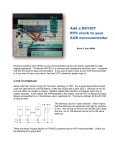
www.robotshop.com
Adafruit DC Boarduino Kit (ATmega328)
RB-Ada-06
Adafruit USB-Boarduino Kit User Manual
RB-Ada-07
Overview........................................................................................................................................3
Differences between the Boarduino and the Arduino....................................................................3
The specifications for the DC boarduino…....................................................................................3
The specifications for the USB boarduino .....................................................................................4
Make It!...........................................................................................................................................4
Preparation……………………………………………………………………………..................4
DC Parts list....................................................................................................................................7
USB Parts List...............................................................................................................................10
Solder it!........................................................................................................................................13
Use it!............................................................................................................................................41
Intro ..............................................................................................................................................41
Using with Arduino IDE ..............................................................................................................41
Using with a breadboard ..............................................................................................................41
Adding USB with an FTDI cable..................................................................................................42
Adding USB with a mini USB (or other USB breakout board) ...................................................43
Arduino-compatibility ..................................................................................................................44
Programming ................................................................................................................................47
Ideas.............................................................................................................................................48
Boarduino
Solderless Breadboard Arduino Clone
Overview
If you've ever struggled to use a solderless breadboard with an Arduino, you understand how frustrating
it can be! I designed this Arduino clone to solve this problem in an inexpensive DIY fashion. Kits with
all parts are available in the Adafruit webshop
The Boarduino is an Arduino clone: when programmed with the Arduino bootloader, it can talk to the
Arduino software and run sketches just like the original.
There are noticable differences between the Boarduino and the Arduino.
• Shields cannot be used as the form factor is so different
• There are two versions, a DC version and a USB version
For the DC version there isn't an on-board USB chip. This means you need to use a USB-TTL cable
or a MiniUSB (or any other FTDI breakout board) which is not included. There are also no rx/tx LEDs
and no rx/tx 1K series resistors.
For the USB version, there is an on-board USB chip but there isn't a DC jack or 5V regulator, you
can power it through the USB jack. There is a rx 1K resistor so you can use this to talk to serial
accessories.
• 16.00 MHz ceramic resonator is used instead of crystal, so cycle speed may be off by +- 0.3nS
(0.5%). This isn't relevant for UART timing, servo drivers, PWM, etc. but could be an issue if you need
nanosecond-precision timing. Note that the Arduino software only provides millisecond-precision
timing for general sketches (1 second = 1000ms. 1ms = 1,000,000 ns)
The specifications for the DC boarduino include:
• Designed to plug into a breadboard for easy prototyping
• Petite size, only 3" x 0.8" (75mm x 20mm)
• All 'standard' pins are brought out - Digital 0 thru 13, Analog 0 thru 5, ARef, 5V, Ground, Vin and
Reset
• 2 LEDs, green power and red "pin 13" LED just like the Arduino Diecimila
• Standard Reset button
• ATmega328P, running at 16.00 MHz, just like the latest Arduino, the Duemilanove (note that the
product photo above hasn't been updated)
• 6-pin standard ICSP header
• Standard 2.1mm DC jack (just like the original Arduino) with 5V regulator to run on 7V-17V power
(DC)
• USB or External power, selectable with a jumper (just like original Arduino)
• 1N4001 diode protects against using incorrect wall adapter
• 6-pin header at the end for a USB-TTL cable
• Auto-reset capability when used with a USB-TTL cable
• Available as a low cost kit with standard parts, so its never out of stock
• All through-hole parts are easy to solder
The specifications for the USB boarduino include:
• Designed to plug into a breadboard for easy prototyping
• Petite size, only 2.75 " x 0.8" (75mm x 20mm)
• All 'standard' pins are brought out - Digital 0 thru 13, Analog 0 thru 5, ARef, 5V, Ground, 3.3V and
Reset
• 2 LEDs, green power and red "pin 13" LED just like the Arduino Diecimila
• Standard Reset button
• ATmega168, running at 16.00 MHz, just like the NG and Diecimila
• 6-pin standard ICSP header
• Standard USB jack
• USB or external power, selectable with a jumper
• 500mA fuse protects your computer from current overdraw
• Auto-reset capability
• Available as a low cost kit with standard parts, so its never out of stock
• All through-hole parts are easy to solder - SMT chip is presoldered & tested when purchased as a kit
Make It!
Preparation
Tools
There are a few tools that are required for assembly. None of these tools are included. If you don't have
them, now would be a good time to borrow or purchase them. They are very very handy whenever
assembling/fixing/modifying electronic devices! I provide links to buy them, but of course, you should
get them whereever is most convenient/inexpensive. Many of these parts are available in a place like
Radio Shack or other (higher quality) DIY electronics stores.
Soldering iron. One with temperature control and a stand is best. A conical or small 'screwdriver' tip is
good, almost all irons come with one of these.
A low quality (ahem, $10 model from radioshack) iron may cause more problems than its worth!
Do not use a "ColdHeat" soldering iron, they are not suitable for delicate electronics work and can
damage the kit.
Solder. Rosin core, 60/40. Good solder is a good thing. Bad solder leads to bridging and cold solder
joints which can be tough to find. Dont buy a tiny amount, you'll run out when you least expect it. A
half pound spool is a minimum.
Multimeter/Oscilloscope A meter is helpful to check voltages and continuity.
Flush/diagonal cutters. Essential for cutting leads close to the PCB.
Desoldering tool. If you are prone to incorrectly soldering parts.
'Handy Hands' with Magnifying Glass. Not absolutely necessary but will make things go much much
faster.
Good light. More important than you think.
DC Parts list
Check to make sure your kit comes with the following parts.Sometimes we make mistakes so double
check everything and email [email protected] if you need replacements!
Image
Name
Description
IC1
Microcontroller
(preprogrammed
with Arduino
bootloader when
purchased in a
kit)
ATmega328P20PU
IC1'
28-pin socket
Generic
X1
ZTT-16.00MT
16.00 MHz
ceramic oscillator
D1
Part #
Distributor
Qty
Digikey
Mouser
1
Adafruit(Pro
grammed)
Digikey
Mouser
1
Digikey
1
2.1mm Power
Jack
CUI PJ-202AH Digikey
1
1N4001 diode
Generic
1N4001
1
Digikey
Mouser
5V regulator
IC2
7805 TO-220
package
C1 C2 C5
C6 (opt)
Generic 7805
Bypass capacitor
Generic
Digikey
Mouser
Generic
Digikey
Mouser
0.1uF ceramic
Electrolytic
capacitor
C3
Digikey
Mouser
47uF / 25V
(or higher)
1
3 or 4
1
C4
100uF/6.3V
capacitor
(or higher)
Generic
Digikey
Mouser
1
R1
10K ohm 1/4W
5% resistor
(brown black
orange gold)
Generic
Digikey
Mouser
1
R2 R3
1.0K 1/4W 5%
resistor (brown
black red gold)
Generic
D3
3mm red LED
Generic
2
Digikey
D2
3mm green LED
Generic
Digikey
1
SW1
6mm tact switch
button
Omron B3FDigikey
1000 (or equiv) Mouser
1
ICSP
6 pin header,
Generic
0.1"x0.1" spacing
Digikey
1
40 pin male
header, 0.1"
spacing
Digikey
1
Generic
Jumper
PCB
Circuit board
1
Adafruit
Industries
1
USB Parts List
Check to make sure your kit comes with the following parts.Sometimes we make mistakes so double
check everything and email [email protected] if you need replacements!
Image
Name
IC1
IC1'
Description
Part #
Distributor
Qty
Digikey
Mouser
Microcontroller
(preprogrammed with
Arduino bootloader when
purchased in a kit)
ATmega328P20PU
28-pin socket
Generic
Digikey
Mouser
1
FTDI FT232RL
Mouser
1
Bournes MFMSMF050-2
Digikey
Mouser
1
Generic
Digikey
Mouser
1
1
Adafruit
(Programmed)
USB interface chip
IC2
Presoldered when purchased
as a kit
Please note that it will
appear as if two pins are
accidentally shorted on
the chip. This is on
purpose! All presoldered
PCBs are tested
500mA resettable Fuse
L1
already soldered on the PCB
X2
USB type B jack
ZTT-16.00MT
X1
C1 C3
C4
Digikey
Mouser
1
Generic
Digikey
Mouser
3
16.00 MHz ceramic oscillator
Bypass capacitor
0.1uF ceramic
C2
100uF/10V capacitor
Generic
Digikey
Mouser
1
R1
10K ohm 1/4W 5% resistor
(brown black orange gold)
Generic
Digikey
Mouser
1
1.0K 1/4W 5% resistor
(brown black red gold)
Generic
3mm red LED
Generic
R2 R3
R4
D3
3
Digikey
D2
3mm green LED
Generic
Digikey
1
SW1
6mm tact switch button
Omron B3F1000 (or
equiv)
Digikey
Mouser
1
ICSP
6 pin header, 0.1"x0.1"
spacing
Generic
Digikey
1
40 pin male header, 0.1"
spacing
Generic
Digikey
1
Jumper
Generic
Digikey
Mouser
1
Circuit board
Custom
Adafruit
Industries
1
PCB
Solder it!
Ready? Set...Solder!
The first step is to solder the kit together. If you've never soldered before, check the Preparation page for tutorials and
more.
Some web browsers (basically, IE) do not like my website so much and load the photonotes slowly. So, if you
are wondering where the rest of the instructions are, either wait a while and IE will eventually display it (below
here). Or download Firefox/Safari which does not have this problem!
Check the kit to verify you have all the
parts necessary
Get your tools ready! A board vise,
soldering iron & solder , diagonal cutters,
and a solder sucker (desoldering tool) if
you have one.
Place the PCB in a vise to make soldering
easy!
Heat up the soldering iron to 700 degrees,
tin it if necessary.
Make sure the sponge is wetted.
Place the 2.1mm DC jack as shown, it
should fit in snugly. Make sure the part is
on the top of the board, so that you can
see the silkscreened images
Use the soldering iron to heat up each of
the 3 connections and poke the solder in
so that it melts into the holes.
Make sure all three pads are soldered,
with plenty of solder, the holes should be
filled up. This gives the jack mechanical
strength.
Next, place the 1N4001 diode D1 . Diodes
are directional, they only let current flow
in one direction. This diode is used to
protect the Boarduino from damage. Make
sure the white stripe on the diode matches
the white stripe in the silkscreened image
below. In this picture, the stripe is on the
right.
You can bend the leads a bit which will
keep the part from falling out when you
turn the board over
Turn the PCB over and solder both legs so
that you get a nice shiny solder joint.
Use the diagonal cutters to clip off the
long leads, leaving just a bump.
It should look like this
Next, its time to place the 25V electrolytic
capacitor C3. Electrolytic capacitors are
polarized which means they only work well
in one direction. Put it in backwards and
they can explode! You can tell how to
place it because the silkscreened image
has a plus near one hole and the capacitor
has one long lead. That lead is the positive
lead. In this image, its the one on the
right.
Also insert C1 which is a ceramic
capacitor. Ceramic capacitors are nonpolarized so you don't have to worry about
putting it backwards
Solder all 4 leads
And clip them short with the cutters.
Next is the 5V regulator. This takes the
power from the DC jack which may be
something like a 9V battery, and brings it
down to 5V, which is suitable for the
microcontroller chip. This part must be
placed as shown, with the metal heat sink
tab on the right.
Turn over the board and solder all three
pins, then clip them off
Now you should soder in the 10V
electrolytic capacitor C4 as shown.
Remember its polarized so you must place
the longer lead in the positive-marked
hole.
Then place the ceramic capacitor C5
Solder in the capacitors and clip them.
Next is the green 3mm LED D2. Like the
electrolytic capacitors, LEDs have polarity
and they wont work if soldered in
backwards. The long lead is the positive
lead, make sure it goes in the hole with a
+ next to it.
The 1K resistor R2 goes in, its the LED's
matching resistor. Bend it over as shown
to place it
Solder in the resistor and LED and clip the
leads
Next you have to make a 3-pin header
Use the diagonal clippers or a pair of pliers
to break apart the single row header.
Place the 3 pin header at the other end of
the board as shown. the short end goes
into the PCB, and the long ends extend
up.
Solder the jumper in place. You won't
need to clip because the leads are short
already!
Place the jumper/shunt as shown, so that
its on the EXT pair of pins
Take the board out of the vise and plug in
a power source such as a 9V DC positivetip wall adapter or a 9V battery with a
2.1mm barrel jack. You should see the
green LED light up.
If no LED lights up check:
Is the battery or wall adapter good?
Is it positive tip?
Is the diode in correctly?
Is the LED in correctly?
Are all the parts in place?
I don't suggest continuing if you can't get
the green LED to light as it indicates a
problem!
Place the red LED D3, taking care to make
sure the long lead is in the positivemarked hole. Also place the matching 1K
resistor R3
Also place the 16.00MHz ceramic oscillator
X1 (which is non-polarized) the third
ceramic capacitor C2 and the 10K resistor
R1
Solder and clip the leads
Place the 28 pin socket. This is to allow
you to replace the microcontroller if
necessary. Make sure the notch in the
socket matches the notch in the
silkscreened image. In this picture, its on
the right
Solder in the socket by tacking two
opposite corners and then soldering the
rest of the pins. Press the socket into the
board to make sure its flat up against it.
Cut another header off, this time a 6-pin
piece.
Place the 6mm reset button, the 6-pin
ICSP header and the 6-pin strip for using
an FTDI USB cable
Solder the parts in
If you'd like to take advantage of the
auto-reset capabilities added to the
Arduino software, install ceramic capacitor
C6.
Now is a good time to insert the IC
Bend the legs gently against a table and
line up the notch in the chip with the notch
in the socket. Carefully seat the chip,
making sure all of the legs are lined up in
the socket.
Cut 4 more pieces of header, a 10-pin, 8pin, 6-pin and 4-pin. Insert them into a
solderless breadboard as shown so that
the long legs are in the solderless
breadboard sockets.
Place the Boarduino on top, so that the
header matches up with the solder holes
in the PCB.
Solder all of the pins of the header,
making sure that the board is sitting flat
against the header.
Carefully remove the boarduino by slowly
rocking it back and forth to release it from
the solderless breadboard.
You should now try to power it up again,
and you will see the green LED light. Press
the reset button, the red LED should blink
a few times. If you don't see the red light
blink make sure the chip is in the right
way
Use it!
Intro
The Boarduino is basically like an Arduino. By default it comes with a chip preprogrammed with the Arduino
bootloader (also known as an STK500v1bootloader) but you can use it as a general purpose AVR module
Using with Arduino IDE
You can use the board as a "Diecimila / Duemilanove" compatible. Dont forget to do the 'autoreset hack below or it
wont auto-reset when its time to program
Remember to check if you have a '168 chip or '328p chip (look at the chip!) ... If you have a '328p select
"Diecimila/Duemilanove with 328P" or you will not be able to talk to it!
Using with a breadboard
The Boarduino is designed to be inserted into a solderless breadboard, any standard breadboard will be suitable.
Simply insert into the breadboard, making sure that the header pins are straight so that they can be easily inserted.
To remove, grab both ends of the board and gently rock back and forth. This will keep the header pins from bending.
Adding USB with an FTDI cable
The easiest way to start loading Arduino sketches into the DC Boarduino is to use a FTDI USB cable. These cables
have the USB chip inside the cable and a 6-pin socket on the end.
This socket plugs into the Boarduino as shown, and then you can simply plug the USB A connector into your
computer. Use the same drivers that you would use with a normal Arduino.
Adding USB with a miniUSB (or other USB breakout board)
Connecting a FTDI breakout board is easy, wire up 5V and ground so that they are shared with the boarduino, then
connect tx and rx. If you are planning to use the 'auto-reset' capability, you will need to place a capacitor (.1uF is just
fine) between the DTR line and the reset pin. For the FTDI cable connector, this capacitor is on the board but since
there may be situations where the reset line for the microcontroller needs to be connected straight to TTL logic, there
is no capacitor on the reset pin.
Arduino-compatibility
The bootloader installed is a cross between the NG and Diecimila. There is a 7-second timeout after pressing the reset
button but once a sketch is uploaded it starts immediately.
If you'd like to have the auto-reset capability, make sure C6 is soldered in. With Mac's and Linux it should just work
fine.
If you're using Windows you'll need to make a slight change to the driver preferences. In the Device Manager, select
the USB COM port
Then right click and select Properties
Click on the Port Settings tab, and click on Advanced...
Make sure Set RTS On Close is selected.
Note that, sadly, the Boarduino will not automatically start the sketch after upload if you do this. Its a bit of a tradeoff
and you may find that pressing the reset button is faster and getting auto-start is better for you.
Programming
There is also a standard 6-pin ICSP (In-Circuit Serial Programming) cable that can be used to burn a new bootloader
or just reprogram the chip.
High power
If you are planning to draw a lot of power from the 5V regulator, say for servos or many LEDs, you
may want to add a heatsink to the 7805. Just bend the regulator back a bit and slip one on.
Ideas...
Intro
Here are some projects built with Boarduinos...just to give you an idea of what's possible!
Use terminal blocks
Terminal screw-blocks allow lightweight ultra-quick prototyping: just tighten the little screws to add or remove
components! Use Phoenix brand 0.1" terminal blocks, part 1725672 (4-position), 1725698 (6-position), 1725711 (8position), 1725724 (9-position)
TodBot's Wii Nunchuck thingy