1
Cyclone for ARM® devices
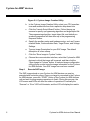
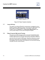
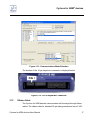
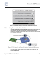
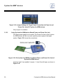
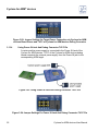
Figure 3-6: Power Connector Locations
3.7
Jumper Settings
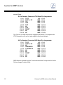
The jumpers must be set differently for various power management options
that the Cyclone for ARM devices offers. If the Cyclone for ARM devices is not
being used to manage the target’s power, only Jumper 5 needs to be
installed. Please see Section 3.13 - Target Power Management for the
correct jumper settings for other power management options.
3.8
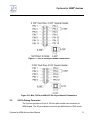
Debug Connector Mechanical Drawing
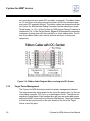
The Cyclone for ARM devices provides one un-keyed standard 20-position
0.100-inch pitch dual row 0.025-inch square header, one keyed 20-position
0.050-inch pitch dual row mini header, and one keyed 10-position 0.050-inch
pitch dual row mini header for ARM targets. Mechanical drawings are shown
below whose dimensions are representative of the pin size and spacing of
these headers (note: the number of pins depicted in the mechanical drawings
may differ from the Cyclone headers).
10
Cyclone for ARM devices User Manual