1
User ’s Manual
WNAP-C3220
300Mbps 802.11n Wireless Ceiling Mount AP /
Range Extender
Copyright
Copyright © 2011 by PLANET Technology Corp. All rights reserved. No part of this publication may be
reproduced, transmitted, transcribed, stored in a retrieval system, or translated into any language or computer
language, in any form or by any means, electronic, mechanical, magnetic, optical, chemical, manual or
otherwise, without the prior written permission of PLANET.
PLANET makes no representations or warranties, either expressed or implied, with respect to the contents
hereof and specifically disclaims any warranties, merchantability or fitness for any particular purpose.
Any
software described in this manual is sold or licensed "as is". Should the programs prove defective following
their purchase, the buyer (and not this company, its distributor, or its dealer) assumes the entire cost of all
necessary servicing, repair, and any incidental or consequential damages resulting from any defect in the
software. Further, this company reserves the right to revise this publication and to make changes from time to
time in the contents hereof without obligation to notify any person of such revision or changes.
All brand and product names mentioned in this manual are trademarks and/or registered trademarks of their
respective holders.
CE mark Warning
This is a class B device, in a domestic environment; this product may cause radio interference, in which case
the user may be required to take adequate measures.
Energy Saving Note of the Device
This power required device does not support Stand by mode operation. For energy saving, please remove the
DC-plug to disconnect the device from the power circuit. Without remove the DC-plug, the device will still
consuming power from the power circuit. In the view of Saving the Energy and reduce the unnecessary power
consuming, it is strongly suggested to remove the DC-plug for the device if this device is not intended to be
active.
R&TTE Compliance Statement
This equipment complies with all the requirements of DIRECTIVE 1999/5/CE OF THE EUROPEAN
PARLIAMENT AND THE COUNCIL OF 9 March 1999 on radio equipment and telecommunication terminal
Equipment and the mutual recognition of their conformity (R&TTE).
The R&TTE Directive repeals and replaces in the directive 98/13/EEC (Telecommunications Terminal
Equipment and Satellite Earth Station Equipment) As of April 8, 2000.
Safety
This equipment is designed with the utmost care for the safety of those who install and use it. However, special
attention must be paid to the dangers of electric shock and static electricity when working with electrical
equipment. All guidelines of this and of the computer manufacture must therefore be allowed at all times to
ensure the safe use of the equipment.
WEEE regulation
To avoid the potential effects on the environment and human health as a result of the presence of
hazardous substances in electrical and electronic equipment, end users of electrical and electronic
equipment should understand the meaning of the crossed-out wheeled bin symbol. Do not dispose of
WEEE as unsorted municipal waste and have to collect such WEEE separately.
Revision
User’s Manual for PLANET 802.11n Wireless Ceiling Mount AP
Model: WNAP-C3220
Rev: 1.0 (April. 2011)
CONTENTS
Chapter 1. Product Introduction...................................................................................................... - 6 1.1
Package Contents............................................................................................................ - 6 -
1.2
Product Description.......................................................................................................... - 6 -
1.3
Product Features.............................................................................................................. - 8 -
1.4
Product Specification........................................................................................................ - 8 -
Chapter 2. Hardware Overview .......................................................................................................- 11 2.1
Hardware Description......................................................................................................- 11 2.1.1
2.1.2
2.1.3
The Front Panel ..................................................................................................- 11 LED Indications...................................................................................................- 11 The Rear Panel.................................................................................................. - 12 -
Chapter 3. Installation..................................................................................................................... - 14 3.1
Mounting Options ........................................................................................................... - 14 -
3.2
Ceiling or Wall Installation .............................................................................................. - 14 -
Chapter 4. Configuring the AP....................................................................................................... - 17 4.1
System Requirements.................................................................................................... - 17 -
4.2
Manual Network Setup - TCP/IP Configuration ............................................................. - 17 -
4.3
Login Web UI.................................................................................................................. - 22 -
4.4
Setup Wizard.................................................................................................................. - 23 4.4.1
4.4.2
Setup – Wireless AP (AP).................................................................................. - 24 Setup – Bridge (WDS) ....................................................................................... - 28 -
Chapter 5. Advanced Settings ....................................................................................................... - 33 5.1
LAN Settings .................................................................................................................. - 33 -
5.2
Wireless Basic Settings.................................................................................................. - 35 -
5.3
Wireless Security Settings ............................................................................................. - 37 5.3.1
5.3.2
AP Security Settings .......................................................................................... - 38 WDS Security Settings ...................................................................................... - 40 -
5.4
Advanced Wireless Settings .......................................................................................... - 41 -
5.5
Connection Status .......................................................................................................... - 43 -
5.6
SNMP Configuration ...................................................................................................... - 44 -
5.7
System Tools .................................................................................................................. - 45 5.7.1
5.7.2
5.7.3
5.7.4
5.7.5
5.7.6
5.7.7
5.8
Change Password ............................................................................................. - 45 Restore to Factory ............................................................................................. - 46 Backup / Restore ............................................................................................... - 47 Time Settings ..................................................................................................... - 47 Reboot ............................................................................................................... - 48 Upgrade ............................................................................................................. - 49 System Log........................................................................................................ - 50 -
Logout ............................................................................................................................ - 50 -
APPENDIX I: WDS Operation Mode Configuration ........................................................................ - 52 P2P: Point to Point Mode ........................................................................................................ - 52 P2MP: Point to Multiple Point Mode........................................................................................ - 54 Repeater Mode:....................................................................................................................... - 56 APPENDIX II:Product Specification .............................................................................................. - 58 -
Figure
Figure 1 WNAP-C3220 Front Panel................................................................................................ - 11 Figure 2 Rear Panel - 1 ................................................................................................................... - 12 Figure 3 Rear Panel - 2 ................................................................................................................... - 12 Figure 4 Mounting the bracket ........................................................................................................ - 14 Figure 5 Connect the RJ-45 Cable.................................................................................................. - 15 Figure 6 Connect the Power Adapter .............................................................................................. - 15 Figure 7 Attach WNAP-C3220 to the bracket ................................................................................. - 16 Figure 8 Ceiling Mounting ............................................................................................................... - 16 Figure 9 Manually assign IP to PC .................................................................................................. - 18 Figure 10 Open Run window........................................................................................................... - 19 Figure 11 Open cmd tool ................................................................................................................. - 19 Figure 12 Success result of Ping command.................................................................................... - 20 Figure 13 Failure result of Ping command ...................................................................................... - 20 Figure 14 Login the AP.................................................................................................................... - 22 Figure 15 Login Window.................................................................................................................. - 22 Figure 16 Web UI Screenshot ......................................................................................................... - 23 Figure 17 Setup Wizard - AP........................................................................................................... - 24 Figure 18 Setup Wizard – Basic Settings of AP .............................................................................. - 25 Figure 19 Setup Wizard – Security Setting of AP ........................................................................... - 25 Figure 20 Setup Wizard – Finish settings of AP.............................................................................. - 27 Figure 21 Setup Wizard – WDS ...................................................................................................... - 29 Figure 22 Setup Wizard - Basic Settings of WDS........................................................................... - 30 Figure 23 Setup Wizard – Security Setting of WDS........................................................................ - 31 Figure 24 Setup Wizard – Finish settings of WDS.......................................................................... - 32 Figure 25 LAN Settings ................................................................................................................... - 33 Figure 26 Wireless Basic Settings .................................................................................................. - 35 Figure 27 Wireless Security Setting ................................................................................................ - 37 Figure 28 Wireless Security Setting – AP ....................................................................................... - 38 Figure 29 Wireless Security Setting – WDS.................................................................................... - 40 Figure 30 Advanced Settings .......................................................................................................... - 41 Figure 31 Wireless Connection Status ............................................................................................ - 43 Figure 32 SNMP Configuration ....................................................................................................... - 44 Figure 33 Change Password........................................................................................................... - 45 Figure 34 Restore to Factory Default Settings ................................................................................ - 46 Figure 35 Backup/Restore............................................................................................................... - 47 Figure 36 Reboot............................................................................................................................. - 48 Figure 37 Upgrade .......................................................................................................................... - 49 Figure 38 System Log ..................................................................................................................... - 50 Figure 39 Logout ............................................................................................................................. - 51 Figure 40 WDS-P2P mode.............................................................................................................. - 53 -
Table
Table 1 WNAP-C3220 Specification Summary................................................................................ - 10 Table 2 The LED indication.............................................................................................................. - 11 Table 3 Button.................................................................................................................................. - 13 Table 4 Interface .............................................................................................................................. - 13 -
User’s Manual of WNAP-C3220
Chapter 1. Product Introduction
1.1 Package Contents
The following items should be contained in the package:
WNAP-C3220 Wireless Ceiling Mount AP
Power Adapter
Ethernet Cable
Mounting Kit (Screw & Plastic wall-plug)
Quick Installation Guide
CD-ROM (User’s Manual included)
If there is any item missed or damaged, please contact the seller immediately.
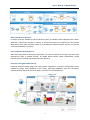
1.2 Product Description
The WNAP-C3220 features 802.11n-compliant radio in 2 x 2 (TX / RX) configuration offering
breakthrough performance and enhances coverage to its Wi-Fi network. The Ceiling Mountable of
300Mbps Wireless Range Extender delivers exceptional range and speed, which can fully meet the
need of Small Office/Home Office (SOHO) networks and the users demanding higher networking
performance, flexible installation.
Faster Speed and Widely Range
Adopting IEEE 802.11n advanced MIMO technology; it provides reliable wireless network coverage,
and incredible improvement in the wireless performance, even in the office with several partitions.
As an IEEE 802.11b/g/n compliant wireless device, the WNAP-C3220 is able to give stable and
efficient wireless performance, while designed with IEEE 802.11b/g/n standard and 2T2R MIMO
technology makes it possible to deliver several times faster data rate up to 300Mbps than normal
wireless device and higher coverage for home and SOHO applications.
Multiple Operating Modes
It supports multiple wireless communication connectivity (AP / Repeater / WDS PtP and PtMP),
allowing for various application requirements that gives user more comprehensive experience when
using WNAP-C3220. It also helps user easily to build wireless network and extend the wireless range
of existed wireless network.
-6-
User’s Manual of WNAP-C3220
Advanced Wireless Security
In aspect of security, besides 64/128- bit WEP encryption, the WNAP-C3220 integrates WPA / WPA2,
WPA-PSK / WPA2-PSK and 802.1x authority to secure and protect your wireless LAN. The wireless
MAC filtering and SSID broadcast control to consolidate the wireless network security and prevent
unauthorized wireless connection.
Easy Installation & Management
With User-friendly Web UI and step by step wizard, it is easier to install, even through a user who never
experiencing setup a wireless network. Its SNMP feature allows system administrator remote
monitoring and controlling network devices more efficiency.
Unique & Ceiling Mountable Design
Featuring attractive Ceiling design and a flying saucer appearance. Its unique ceiling design can be
installed by simply firmly adsorbed on the ceiling, client-side installation easy and convenient,
streamlined body effects on the surrounding environment more embellishment.
-7-
User’s Manual of WNAP-C3220
1.3 Product Features
¾
¾
Compliance with Industrial Standard
Compliant with IEEE 802.11n wireless technology capable of up to 300Mbps data rate
Backward compatible with 802.11b/g standard
Gigabit Auto-negotiation LAN port, Compliant with IEEE 802.3/802.3u standards
Support 802.3af standard-based PoE or local AC power
Secure Network Connection
¾
Advanced security:
-
64 / 128-bit WEP
-
WPA / WPA2
-
WPA-PSK / WPA2-PSK (TKIP/AES encryption)
-
IEEE 802.1x Network Access Control
Support MAC Address Filtering Access Control to limit the connected wireless clients
Multiple Operating Modes, Multiple Mounting Options
Multiple operating modes including AP, Repeater, WDS Point to Point, WDS Point to
Multiple Point
¾
Ceiling mountable characterizes can reach better coverage to reduce dead spot
Easy Installation & Management
Step by Step configuration with Intelligent Setup Wizard
User-friendly Web and SNMP-based management interface
System status monitoring includes Associated Client List, System Log
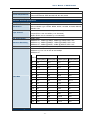
1.4 Product Specification
Product
WNAP-C3220
300Mbps 802.11n Wireless Ceiling Mount Access Point
Hardware Specification
Standard support
PoE
Interface
Antenna
LED
IEEE 802.11b/g
IEEE 802.11n
IEEE 802.3 10Base-T
IEEE 802.3u 100Base-TX
IEEE 802.3ab 1000Base-T
IEEE 802.3x Flow Control
IEEE 802.3af Power over Ethernet
802.3af PoE
Wireless IEEE 802.11b/g/n
LAN: 1x 10/100/1000Base-T, Auto-MDI/MDIX, 802.3af PoE compliant
Built-in 2T2R, 2dbi Printed Antenna
Wireless / Power LED
-8-
User’s Manual of WNAP-C3220
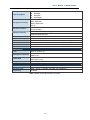
Button
Power Requirements
Power Consumption
Reset
Power Supply: DC 12V, 1A
Power over Ethernet: IEEE 802.3af PoE, DC 48V, 0.35A
≦ 6W
Wireless Interface Specification
Frequency Band
Modulation
2.4~2.4835GHz
Transmission/Emission Type: DSSS / OFDM
Data modulation type: OFDM: BPSK, QPSK, 16-QAM, 64-QAM, DBPSK,
DQPSK, CCK
America/ FCC: 2.412~2.462GHz (1~11 Channels)
Opt. Channel
Europe/ ETSI: 2.412~2.472GHz (1~13 Channels)
Japan/ TELEC: 2.412~2.484GHz (1~14 Channels)
RF Output Power
Receiver Sensitivity
TX Power
20dBm (Max.)
IEEE 802.11b: -92dBm @ 1Mbps; -85dBm @ 11Mbps, PER < 8%
IEEE 802.11g: -88dBm @ 6Mbps; -73dBm @ 54Mbps, PER <10%
IEEE 802.11n: -90dBm @ MCS8; -70dBm @ MCS15, PER <10%
User defined (Range 1~100, default 100)
IEEE 802.11b: 1/ 2/ 5.5/ 11Mbps
IEEE 802.11g: 6/ 9/ 12/ 18/ 24/ 36/ 48/ 54Mbps
IEEE 802.11n:
Guard Interval 800ns
Guard Interval 400ns
MCS
20MHz(Mbps) 40MHz(Mbps) 20MHz(Mbps) 40MHz(Mbps)
Data Rate
0
6.5
13.5
7.2
15
1
13
27
14.4
30
2
19.5
40.5
21.7
45
3
26
54
28.9
60
4
39
81
43.3
90
5
52
108
57.8
120
6
58.5
121.5
65
135
7
65
135
72.2
157.5
8
13
27
14.4
30
9
26
54
28.9
60
10
39
81
43.3
90
11
52
108
57.8
120
12
78
162
86.7
180
13
104
216
115.6
240
14
117
243
130
270
15
130
270
144.4
300
Wireless Management Features
-9-
User’s Manual of WNAP-C3220
Operating Mode
Encryption Security
Wireless Isolation
Wireless Security
Wireless Client Max.
WMM
BG Protection Mode
APSD
Max. WDS AP
Max. Wired Client
Management
LAN
AP
Repeater
WDS PtP
WDS PtMP
64/128-bits WEP
WPA, WPA-PSK
WPA2, WPA2-PSK
802.1X
Enable it to isolate each connected wireless clients, to let them cannot
access mutually.
Wireless MAC address filtering (up to 50 entries)
SSID broadcast and Hide
20 (default 10)
Wi-Fi Multimedia for better data transmission of Video or on-line demand
A protection mechanism prevents collisions among 802.11b/g modes
For auto power-saved service
4
Unlimited
Static IP, Dynamic IP
Web UI
Management Interface
SNMPv1/v2c
MIB I
SNMP MIB
MIB II (RFC-1213)
Diagnostic tool
System Log
Environment & Certification
Operation Temp.
Temp.: 0~40°c, Humidity: 10%~90% non-condensing
Storage Temp.
Temp.: -40~70°c, Humidity: 5%~90% non-condensing
Regulatory
CE/RoHS
Table 1 WNAP-C3220 Specification Summary
- 10 -
User’s Manual of WNAP-C3220
Chapter 2. Hardware Overview
2.1 Hardware Description
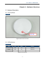
2.1.1 The Front Panel
Front Panel
Power LED
Figure 1 WNAP-C3220 Front Panel
2.1.2 LED Indications
LED Definition
LED
Power
Color
Status
Function
Green
On
System On
Green
Off
System Off
Green
Flashing
Device Initial
Table 2 The LED indication
- 11 -
User’s Manual of WNAP-C3220
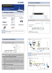
2.1.3 The Rear Panel
Gigabit LAN Port, 802.3af PoE
Reset Button
Figure 2 Rear Panel - 1
Power Jack (12V, 1A)
Figure 3 Rear Panel - 2
- 12 -
User’s Manual of WNAP-C3220
Reset Button
ACTIVE
Function
Press and hold the button more than 6 seconds to the factory default setting
Reset
Table 3 Button
Interface
Interface
Function
The Power socket is where you will connect the power adapter.
POWER
Please use the power adapter provided with WNAP-C3220.
The LAN Port is where you will connect the RJ-45 Ethernet cable.
LAN
The LAN Port also support 802.3af PoE.
Table 4 Interface
1.
For the power supply of WNAP-C3220, you could use either IEEE
802.3af PSE device or 12VDC Adapter.
Power Notice:
2.
Please do not use 12V adapter and PSE devices at the same time. It may
damage the WNAP-C3220 itself.
ONLY use the power adapter supplied with WNAP-C3220. Otherwise, the
product may be damaged.
- 13 -
User’s Manual of WNAP-C3220
Chapter 3. Installation
3.1 Mounting Options
The following types of surfaces that is suitable to mount WNAP-C3220:
Ceiling
Solid surface wall
Tabletop
If you plan to install an AP on a partial wall or other vertical surface, orient the top of the
access point (white cover) toward the intended coverage area. The radio antennas
transmit through the top of the access point but not through the bottom (where the
bracket is).
3.2 Ceiling or Wall Installation
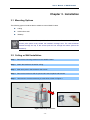
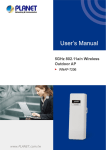
Step 1. Remove the mounting bracket from the WNAP-C3220.
Step 2. Attach the bracket to the wall or ceiling.
Step 3. Mark each point in the bracket for the screws.
Step 4. Remove the bracket to drill the points and insert the plastic wall-mounts.
Step 5. Use screws to lock the bracket by a screw driver, shown in Figure 4.
Figure 4 Mounting the bracket
- 14 -
User’s Manual of WNAP-C3220
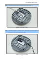
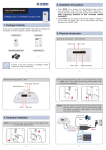
Step 6. Plug the RJ-45 Ethernet cable into the WNAP-C3220, shown in Figure 3-2.
Figure 5 Connect the RJ-45 Cable
Step 7. Plug the power adapter into the WNAP-C3220. If WNAP-C3220 is connected to an 802.3af
PoE switch, you don’t have to plug the power adapter.
Figure 6 Connect the Power Adapter
- 15 -
User’s Manual of WNAP-C3220
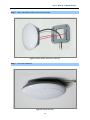
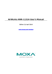
Step 8. Attach the WNAP-C3220 to the mounting bracket.
Figure 7 Attach WNAP-C3220 to the bracket
Step 9. Successful installation.
Figure 8 Ceiling Mounting
- 16 -
User’s Manual of WNAP-C3220
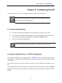
Chapter 4. Configuring the AP
This chapter will show you how to configure the basic functions of your Wireless AP.
A computer with wired Ethernet connection to the Wireless Router is
required for the first-time configuration.
4.1 System Requirements
PCs with a working Ethernet Adapter and an Ethernet cable with RJ-45 connectors
PC of subscribers running Windows 98/ME, NT4.0, 2000/XP, Windows Vista / Win 7, MAC
OS 9 or later, Linux, UNIX or other platform compatible with TCP/IP protocols
Above PC installed with WEB Browser
It is recommended to use Internet Explore 7.0 or above to access the Router.
4.2 Manual Network Setup - TCP/IP Configuration
The default IP address of the WNAP-C3220 is 192.168.1.1. And the default Subnet Mask is
255.255.255.0. These values can be changed as you desire. In this guide, we use all the default values
for description.
Connect the local PC to the LAN ports of the AP. And then you can configure the IP address for your
PC.
In the following sections, we’ll introduce how to install and configure the TCP/IP correctly in Windows
XP. First, make sure your Ethernet Adapter is working, and refer to the Ethernet adapter’s manual if
needed.
- 17 -
User’s Manual of WNAP-C3220
Summary:
Set up the TCP/IP Protocol for your PC.
Configure the network parameters. The IP address is 192.168.1.xxx ("xxx" is any number
from 2 to 254), Subnet Mask is 255.255.255.0.
1
Select Use the following IP address radio button.
2
If the AP's LAN IP address is 192.168.1.1, enter IP address 192.168.1.x (x is from 2 to 254), and
Subnet mask 255.255.255.0.
Figure 9 Manually assign IP to PC
Now click OK to save your settings.
Now, you can run the Ping command in the command prompt to verify the network connection
between your PC and the AP. The following example is in Windows XP OS. Please follow the steps
below:
- 18 -
User’s Manual of WNAP-C3220
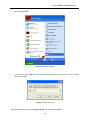
1.
Click on Start > Run.
Figure 10 Open Run window
2.
In the run box type “cmd” and click OK. (Windows Vista users type cmd in the Start .Search
box.)At the prompt.
Figure 11 Open cmd tool
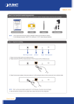
Open a command prompt, and type ping 192.168.1.1, and then press Enter.
- 19 -
User’s Manual of WNAP-C3220
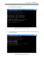
If the result displayed is similar to the figure below, it means the connection between your
PC and the AP has been established well.
Figure 12 Success result of Ping command
If the result displayed is similar to the figure below, it means the connection between your
PC and the AP has failed.
Figure 13 Failure result of Ping command
- 20 -
User’s Manual of WNAP-C3220
If the address is 0.0.0.0, check your adapter installation, security settings, and the settings on your AP.
Some firewall software programs may block a DHCP request on newly installed adapters.
1.
If the AP's IP address is 192.168.1.1, your PC's IP address must be within the
range of 192.168.1.2 ~ 192.168.1.254.
- 21 -
User’s Manual of WNAP-C3220
4.3 Login Web UI
It is easy to configure and manage the WNAP-C3220 with web browser.
Step 1.
To access the configuration utility, open a web-browser and enter the default IP address
http://192.168.1.1 in the address field of the browser.
Figure 14 Login the AP
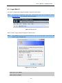
After a moment, a login window will appear as Figure below.
Step 2.
Enter admin for the User Name and Password, both in lower case letters. Then click the OK
button or press the Enter key.
Figure 15 Login Window
Default User name: admin
Default Password: admin
- 22 -
User’s Manual of WNAP-C3220
If the above screen does not pop up, it may mean that your web-browser has been set to
a proxy. Go to Tools menu>Internet Options>Connections>LAN Settings, in the screen
that appears, cancel the Using Proxy checkbox, and click OK to finish it.
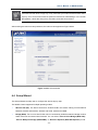
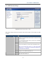
After entering the username and password, the main screen appears as Figure below.
Figure 16 Web UI Screenshot
4.4 Setup Wizard
The Setup Wizard can help user to configure the device step by step.
The WNAP-C3220 supported multiple operating modes:
Wireless AP (AP): The device works as a wireless HUB in this mode, making communications
between wireless and wireless, wireless and wired, wireless and WAN.
Bridge (WDS): Two or more wired LANs can be connected by wireless method in Bridge mode to
share resources and extend wired network. You can select “Point to Point Bridge (WDS P2P)”,
“Point to Multipoint Bridge (WDS P2MP)” or “Wireless Repeater (WDS AP Repeater)” mode.
- 23 -
User’s Manual of WNAP-C3220
4.4.1 Setup – Wireless AP (AP)
The AP mode can convert the wired transmission into wireless signals. If you have one wired cable
connecting to Internet, and want to access the Internet via wireless signals connecting to your
notebook computer, this mode fits perfectly.
Step 1.
Click the Setup Wizard to quickly configure your WNAP-C3220 to act as AP.
Figure 17 Setup Wizard - AP
Step 2. Select Wireless AP (AP), and then click Next to enter the Basic Settings page, shown in
Figure below.
- 24 -
User’s Manual of WNAP-C3220
Figure 18 Setup Wizard – Basic Settings of AP
Fill in the following items according to the reminder information.
SSID: Set the SSID of the device. The default SSID is “default”.
Channel: Select the wireless communication channel. The default is channel 6.
Step 3.
After finish the setting, click Next to enter Security Settings page, shown in Figure below.
Figure 19 Setup Wizard – Security Setting of AP
- 25 -
User’s Manual of WNAP-C3220
The Security Setting page is used to configure the AP network’s security.
There are following encryption types in AP-Security Mode.
AP-Security
Object
Description
Disable
The wireless security function can be enabled or disabled.
If disabled, the wireless stations will be able to connect to
the AP without encryption. It is recommended strongly that
you choose one of following options to enable security.
Mode
WPA-PSK
It is a simplified WPA mode with no need for specific
authentication server.
In this so-called WPA Pre-Shared Key, all you have to do is
just pre-enter a key in each WLAN node and this is the
common way to be adopted in large and middle enterprise
as well as residential network.
WPA2-PSK
As a new version of WPA, only all the clients support
WPA2, can it be available.
If it is selected, the data encryption can only be AES and
the passphrase is required.
Mixed
WPA/WPA2-PSK
It provides options of WPA (TKIP) or WPA2 (AES)
encryption for the client.
If it is selected, the data encryption can only be TKIP +
AES and the passphrase is required.
Open Mode
It allows any device to join the network without performing
any security check.
Shared Mode
Data encryption and key are required for wireless
authentication.
WEP Mixed Mode
WEP (Wired Equivalent Privacy), a basic encryption
method, usually encrypts wireless data using a series of
digital keys (64 bits or 128 bits in length). By using the
same keys on each of your wireless network devices, you
can prevent unauthorized wireless devices from
monitoring your transmissions or using your wireless
resources. WEP is based on RSA algorithm from RC4. It is
the original and weak encryption method, so it is
recommended not to use this method.
WPA-Enterprise
With warrant (username, password and etc.) offered by
user, this kind of authentication can be realized with
specific RADIUS server. This is the common way to be
adopted in large enterprise network.
WPA2-Enterprise
You can use a RADIUS server to authenticate wireless
stations and provide the session key to encrypt data during
communication. It uses TKIP or CCMP (AES) to change
the encryption key frequently.
Mixed
It provides options of WPA (TKIP) or WPA2 (AES) for the
client. If it is selected, the data encryption type must be
- 26 -
User’s Manual of WNAP-C3220
WPA/WPA2-Enterprise
TKIP + AES and the RADIUS server must be set.
802.1X
This security mode is used when a RADIUS server is
connected to the device. 802.1x, a kind of Port-based
authentication protocol, is an authentication type and
strategy for users. The port can be either a physic port or
logic port (such as VLAN). For wireless LAN users, a port
is just a channel. The final purpose of 802.11x
authentication is to check if the port can be used. If the
port is authenticated successfully, you can open this port
which allows all the messages to pass. If the port isn’t
authenticated successfully, you can keep this port
“disable” which just allows 802.1x authentication protocol
message to pass.
We strongly recommend you enable wireless security on your network!
Only setting the same Authentication, Data Encryption and Key in the WNAP-C3220 and
other associated wireless devices, can the communication be established!
Step 4.
After finish the setting, click Next to finish the Setup as shown in Figure below.
Figure 20 Setup Wizard – Finish settings of AP
Step 5.
Click Save to save the configuration.
- 27 -
User’s Manual of WNAP-C3220
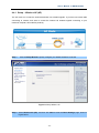
4.4.2 Setup – Bridge (WDS)
Bridge (WDS) mode includes P2P, P2MP, and Wireless Repeater.
P2P: P2P bridge mode can connect with two wired network via wireless access points, which
communicate by wireless signals and not by cables. This mode can be free from the cable
trouble. The P2P topology shows below:
P2P / PtP: Point to Point Mode
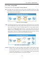
P2MP: The P2MP Bridge Mode which connects scattered wired network together is more complicated
than P2P Bridge mode. P2MP usually transmit wireless signals from one access point, and
other access points are in charge of receiving signals so as to share network resource.
Support up to 4 remote access point connection. In this mode, wireless clients are not
allowed to connect. P2MP Bridge mode can connect multiple wireless access point together
without cabling. If “Root AP” is configured as P2MP bridge mode, other (less than 4) remote
access points should select P2P bridge modes. The topology shows below:
P2MP / PtMP: Point to Multiple Point Mode
Repeater: Repeater Mode can repeat and amplify wireless signals to extend wireless network
coverage. In this mode, wireless clients are allowed to connect. When two LAN’s
transmission distance is over the wireless device’s maximum transmission value, or there
is much block among devices, you can use the Repeater mode to deal with these
problems by adding MAC addresses. The topology shows below:
- 28 -
User’s Manual of WNAP-C3220
WDS Repeater Mode
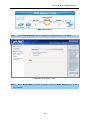
Step 1.
Click the Setup Wizard to quickly configure your WNAP-C3220 to act as Bridge.
Figure 21 Setup Wizard – WDS
Step 2.
Select Bridge (WDS), and then click Next to enter the Basic Settings page, shown in
Figure below.
- 29 -
User’s Manual of WNAP-C3220
Figure 22 Setup Wizard - Basic Settings of WDS
Configure the following fields before enter to the Next page.
Object
Description
WDS Mode
Bridge (WDS) mode includes WDS P2P, WDS P2MP, and WDS AP
Repeater
AP MAC
Enter the interconnection equipment’s MAC address.
Channel
Select the channel according to interconnection equipment’s; the
devices on the two ends must be at the same channel.
Open Scan
Click this button, the AP will scan the nearby wireless devices
automatically and display the information in the table.
Select the device which need to bridge, the AP will add the device’s
MAC address automatically and select the corresponding channel.
- 30 -
User’s Manual of WNAP-C3220
Step 3.
After finish the setting, click Next to enter Security Settings page, shown in Figure 23.
Figure 23 Setup Wizard – Security Setting of WDS
This page includes AP Security Settings and WDS Security Settings. Select one of the encryption
methods for the WDS connection.
WDS security setting provides three encryption modes: WEP encryption, TKIP encryption and
AES encryption.
Object
WDS-Security Mode
Description
Disable
The wireless security function can be enabled or disabled. If
disabled, the wireless stations will be able to connect to the AP
without encryption. It is recommended strongly that you choose
one of following options to enable security.
WEP
It is based on the IEEE 802.11 standard.
You can set the WEP key in ASCII code or Hexadecimal code.
Key: You can choose ASCII code (5 or 13 ASCII codes, illegal
characters like “/” are forbidden) or Hexadecimal characters (10
or 26 Hexadecimal characters).
TKIP
Temporal Key Integrity Protocol, which is a kind of dynamic
encryption, is co-used with WPA-PSK, etc.
AES
Advanced Encryption Standard, it is usually co-used with
WPA2-PSK, WPA, WPA2, etc.
- 31 -
User’s Manual of WNAP-C3220
We strongly recommend you enable wireless security on your network!
Only setting the same Authentication, Data Encryption and Key in the WNAP-C3220 and
other associated wireless devices, can the communication be established!
Step 4.
After finish the setting, click Next to finish the Setup as shown in Figure below.
Figure 24 Setup Wizard – Finish settings of WDS
Step 5.
Click Save to save the configuration.
- 32 -
User’s Manual of WNAP-C3220
Chapter 5. Advanced Settings
This chapter will show you how to configure the advanced functions of your Wireless AP.
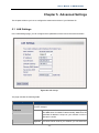
5.1 LAN Settings
In the LAN Settings page, you can configure the IP parameters of the LAN on the screen as below.
Figure 25 LAN Settings
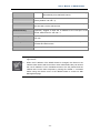
The page includes the following fields:
Object
Description
MAC Address
The physical address of the Router, as seen from the LAN. The value
can't be changed.
IP Method
Static IP
Specify a static IP address, subnet mask, default gateway
and DNS server for WNAP-C3220 manually. Make sure the
specified IP address is unique on your network in order to
prevent IP conflict.
Dynamic
If a DHCP server exists in your network, you can select this
- 33 -
User’s Manual of WNAP-C3220
option, thus the WNAP-C3220 is able to obtain IP settings
automatically from that DHCP server.
IP Address
Enter the IP address of your Router or reset it in dotted-decimal notation
(factory default: 192.168.1.1).
Subnet Mask
An address code that determines the size of the network. Normally use
255.255.255.0 as the subnet mask.
Default Gateway
(Optional.) Suggest to input the IP address of the LAN port of the
Router, default value is 192.168.1.1
Primary DNS Server
(Optional.) Input the DNS IP address provided by your ISP. Or consult
your ISP.
Secondary DNS Server
(Optional.) Input the IP address of another DNS server if your ISP
provides two DNS servers.
Host name
(Optional.) This option specifies the Host Name of the AP.
1.
If you change the IP Address of LAN, you must use the new IP Address to
login the AP.
2.
When the IP address of the WNAP-C3220 is changed, the clients on the
network often need to wait for a while or even reboot before they can access
the new IP address. For an immediate access to the AP, please flush the
netbios cache on the client computer by running the “nbtstat –r” command
before using the device name of the WNAP-C3220 to access its Web
Management page.
- 34 -
User’s Manual of WNAP-C3220
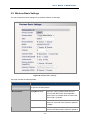
5.2 Wireless Basic Settings
You can configure the basic settings for the wireless network on this page.
Figure 26 Wireless Basic Settings
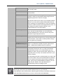
The page includes the following fields:
Object
Description
Wireless Enable
Click “Disable” to shut all the wireless feature of this AP; click “Enable”
to open the wireless feature.
Wireless Mode
11b/g Mixed Mode
Allow the 11b/g-compliant client device to
connect with the AP with auto-negotiation
speed, and 11n wireless client to connect the
device with 11g speed.
11b Mode
Allow the wireless client to connect with the
device in 11b mode at the maximum speed of
11Mbps.
11g Mode
Allow the 11g/11n-compliant client device to
connect with the AP at the maximum speed of
- 35 -
User’s Manual of WNAP-C3220
54Mbps.
11b/g/n Mixed Mode
Allow 11b/g/n-compliant client device to
connect with the AP with auto- negotiation
speed. The maximum speed is 300Mbps.
SSID
SSID (Service Set Identifier) is the unique name of the wireless
network. It is recommended to modify this name for wireless client to
recognize wireless signals.
Broadcast(SSID)
When you select “Disable SSID broadcast”, AP will not broadcast its
own SSID number.
If there is a wireless connection request, you need to input SSID
number manually.
BSSID
Basic Service Set Identifier of wireless network. In IEEE802.11, BSSID
is the MAC address of wireless access point.
WLAN Isolation
The access control feature based on wireless MAC address.
When this feature is enabled, each of your wireless clients will be in its
own virtual network and will not be able to communicate with each
other. This feature is to isolate the
communication of wireless clients connected with different AP.
Channel
Specify the effective channel (from 1 to 13\Auto) of the wireless
network.
Operation Mode
Choose this according to the wireless mode(s) used in your network.
Mixed Mode - Select this if the wireless clients in your network use
different wireless modes (for example, IEEE 802.11b/g and IEEE
802.1n modes)
Green Mode - Select this if the wireless clients in your network uses
only one type of wireless mode (for example, IEEEE 802.11 n only)
Channel Bandwidth
Select the proper channel bandwidth to improve the wireless
performance. 20M bandwidth can improve the anti-jamming ability of
the wireless device. 40M bandwidth can improve the flux of 11N client.
Guard Interval
This function is recommended for it will increase the data capacity by
reducing the guard interval time.
Reverse Direction
Grant(RDG)
Disable or enable reserve direction grant.
Default is enabled.
Extension Channel
To increase data throughput of wireless network, the extension channel
range is used in 11n mode.
Aggregation MSDU
The data rate of your AP except wireless client mode, could be
enhanced greatly with this option enabled; however, if your wireless
clients don’t support MSDU aggregation, it is not recommended to
enable it.
- 36 -
User’s Manual of WNAP-C3220
5.3 Wireless Security Settings
You can configure the security settings for the wireless network on this page.
Figure 27 Wireless Security Setting
This page includes AP Security Settings and WDS Security Settings. If you have configured the
wireless working mode to AP in Setup Wizard, then this page will start from AP Security Settings.
If you have configured the wireless working mode to WDS in Setup Wizard, then this page will
start from WDS Security Settings. Select one of the encryption methods for your wireless
connection.
- 37 -
User’s Manual of WNAP-C3220
5.3.1 AP Security Settings
Figure 28 Wireless Security Setting – AP
There are following encryption types in AP-Security Mode.
AP-Security
Mode
Object
Description
Disable
The wireless security function can be enabled or disabled.
If disabled, the wireless stations will be able to connect to
the AP without encryption.
It is recommended strongly that you choose one of
following options to enable security.
WPA-PSK
It is a simplified WPA mode with no need for specific
authentication server. In this so-called WPA Pre-Shared
Key, all you have to do is just pre-enter a key in each
WLAN node and this is the common way to be adopted in
large and middle enterprise as well as residential network.
WPA2-PSK
As a new version of WPA, only all the clients support
WPA2, can it be available. If it is selected, the data
encryption can only be AES and the passphrase is
required.
Mixed
WPA/WPA2-PSK
It provides options of WPA (TKIP) or WPA2 (AES)
encryption for the client. If it is selected, the data
encryption can only be TKIP + AES and the passphrase is
required.
- 38 -
User’s Manual of WNAP-C3220
Open Mode
It allows any device to join the network without performing
any security check.
Shared Mode
Data encryption and key are required for wireless
authentication.
WEP Mixed Mode
WEP (Wired Equivalent Privacy), a basic encryption
method, usually encrypts wireless data using a series of
digital keys (64 bits or 128 bits in length).
By using the same keys on each of your wireless network
devices, you can prevent unauthorized wireless devices
from monitoring your transmissions or using your wireless
resources. WEP is based on RSA algorithm from RC4. It is
the original and weak encryption method, so it is
recommended not to use this method.
WPA-Enterprise
With warrant (username, password and etc.) offered by
user, this kind of authentication can be realized with
specific RADIUS server. This is the common way to be
adopted in large enterprise network.
WPA2-Enterprise
You can use a RADIUS server to authenticate wireless
stations and provide the session key to encrypt data during
communication. It uses TKIP or CCMP (AES) to change
the encryption key frequently.
Mixed
WPA/WPA2-Enterprise
It provides options of WPA (TKIP) or WPA2 (AES) for the
client. If it is selected, the data encryption type must be
TKIP + AES and the RADIUS server must be set.
802.1X
This security mode is used when a RADIUS server is
connected to the device. 802.1x, a kind of Port-based
authentication protocol, is an authentication type and
strategy for users. The port can be either a physic port or
logic port (such as VLAN). For wireless LAN users, a port
is just a channel.
The final purpose of 802.1x authentication is to check if the
port can be used. If the port is authenticated successfully,
you can open this port which allows all the messages to
pass. If the port isn’t authenticated successfully, you can
keep this port “disable” which just allows 802.1x
authentication protocol message to pass.
We strongly recommend you enable wireless security on your network!
Only setting the same Authentication, Data Encryption and Key in the WNAP-C3220 and
other associated wireless devices, can the communication be established!
- 39 -
User’s Manual of WNAP-C3220
5.3.2 WDS Security Settings
Figure 29 Wireless Security Setting – WDS
WDS security setting provides three encryption modes: WEP encryption, TKIP encryption and AES
encryption.
Object
WDS-Security Mode
Description
Disable The wireless security function can be enabled or disabled. If
disabled, the wireless stations will be able to connect to the AP
without encryption.
It is recommended strongly that you choose one of following
options to enable security.
WEP
It is based on the IEEE 802.11 standard.
You can set the WEP key in ASCII code or Hexadecimal code.
Key: You can choose ASCII code (5 or 13 ASCII codes, illegal
characters like “/” are forbidden) or Hexadecimal characters (10
or 26 Hexadecimal characters).
TKIP
Temporal Key Integrity Protocol, which is a kind of dynamic
encryption, is co-used with WPA-PSK, etc.
AES
Advanced Encryption Standard, it is usually co-used with
WPA2-PSK, WPA, WPA2, etc.
- 40 -
User’s Manual of WNAP-C3220
We strongly recommend you enable wireless security on your network!
Only setting the same Authentication, Data Encryption and Key in the WNAP-C3220 and
other associated wireless devices, can the communication be established!
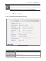
5.4 Advanced Wireless Settings
You can configure advanced wireless parameters on this page.
Figure 30 Advanced Settings
The page includes the following fields:
Object
BG Protection Mode
Description
For 11b/g wireless client, it is easier to connect with 11n wireless device.
The default is “Auto”.
Basic Data Rates
In term of different requirements, you can select one of the suitable
- 41 -
User’s Manual of WNAP-C3220
Basic Data Rates from the drop-down menu.
Here, default value is (1-2-5.5-11Mbps…). It is recommended not to
modify the default value.
Beacon Interval
The frequency interval of the beacon, which is a packet broadcast by an
AP to synchronize a wireless network.
The default value is 100 ms.
Fragment Threshold
The fragmentation threshold defines the maximum transmission packet
size in bytes. The packet will be fragmented if the arrival is bigger than
the threshold setting.
The default size is 2346 bytes.
RTS Threshold
RTS stands for “Request to send”. This parameter controls what size
data packet the frequency protocol issues to RTS packet. If the device
works in SOHO, do not modify the default value.
TX Power
Set the wireless output power level.
The default value is 100.
WMM Capable
To enhance wireless multimedia transfer performance (0n-line video
and voice). If you are not clear about this, enable it.
APSD Capable
It is used for auto power-saved service.
The default is disabled.
The limited of client
Limit the total number of the wireless client.
The maximum is 20, and the default value is 10.
Wireless LED
Turn on or turn off the Wireless LED.
The default is On.
- 42 -
User’s Manual of WNAP-C3220
5.5 Connection Status
This page will display the current wireless connection status as shown below:
Figure 31 Wireless Connection Status
MAC Address: Shows current connecting host’s MAC address.
Bandwidth: Shows current connecting host’s (wireless client) bandwidth (20MHz or 40MHz).
- 43 -
User’s Manual of WNAP-C3220
5.6 SNMP Configuration
Simple Network Management Protocol (SNMP) is a popular protocol for network management. It is
widely used in local area networks (LAN) for collecting information, and managing and monitoring,
network devices, such as servers, printers, hubs, switches, and routers from a management host.
Managed devices that support SNMP including software are referred to as an SNMP agent, which
usually interacts with third-party SNMP management software to enable the sharing of network status
information between monitored devices and applications and the SNMP management system.
A defined collection of variables (managed objects) are maintained by the SNMP agent and used to
manage the device. These objects are defined in a Management Information Base (MIB), which
provides a standard presentation of the information controlled by the on-board SNMP agent. SNMP
defines both the format of the MIB specifications and the protocol used to access this information over
the network.
Figure 32 SNMP Configuration
This device supports SNMP v1 and SNMP v2c. Please click “SNMP Setting” in the left page to enter
this page.
Click “Enable” or “Disable” to enable and disable SNMP management.
The page includes the following fields:
Object
Description
Contact
Set the name to access the AP. Usually set the administrator’s name.
Device Name
Set the AP’s name, such as “WNAP-C3220”.
- 44 -
User’s Manual of WNAP-C3220
Location
Set the AP’s network location.
Read Community
Indicates the community read access string to permit reading this AP’s
SNMP information.
The default is Public.
Read/Write Community
Indicates the community read/write access string to permit reading and
re-writing this AP’s SNMP information.
The default is Private.
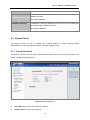
5.7 System Tools
This section focuses on how to maintain AP, including Restore to Factory Default Setting,
Backup/Restore, Firmware Upgrade, Reboot, Password Change, Syslog.
5.7.1 Change Password
This section is to set a new user name and password to better secure your device and network. Click
“Apply” to finish changing password.
Figure 33 Change Password
User Name: Enter a new user name for the device.
Old Password: Enter the old password.
- 45 -
User’s Manual of WNAP-C3220
New Password: Enter a new password.
Re-enter to Confirm: Re-enter to confirm the new password.
It is highly recommended to change the password to secure your network and the
device.
5.7.2 Restore to Factory
This button is to reset all configurations to the default values. It means the device will lose all the
settings you have set.
Figure 34 Restore to Factory Default Settings
Restore: Click this button to restore to default settings.
Factory Default Settings:
User name: admin
Password: admin
IP Address: 192.168.1.1
Subnet Mask: 255.255.255.0
- 46 -
User’s Manual of WNAP-C3220
5.7.3 Backup / Restore
The device provides backup/restore settings, so you need set a directory to keep these settings.
Figure 35 Backup/Restore
Backup: Click this button to back up the device’s configurations.
Browse: Click this button to browse the directory where you backup or save the device’s
settings.
Restore: Click this button to restore the device’s configurations.
5.7.4 Time Settings
This section is to select the time zone for your location. You can select your own time or obtain the
standard GMT time from Internet.
- 47 -
User’s Manual of WNAP-C3220
Figure 36 Time Settings
Time Zone: Select your time zone from the drop-down menu.
Customized time: Enter the time you customize.
5.7.5 Reboot
This page is used to reboot wireless access point. Rebooting the device makes the settings configured
go into effect.
Figure 36 Reboot
Reboot: Click this button to reboot the device.
- 48 -
User’s Manual of WNAP-C3220
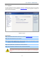
5.7.6 Upgrade
The device provides the firmware upgrade by clicking the “Upgrade” after browsing for the firmware
upgrade packet which you can download from www.planet.com.tw. After the upgrade is completed, the
device will reboot automatically.
Figure 37 Upgrade
Upgrade Steps:
Step 1. Download the latest firmware version from our website: www.planet.com.tw.
Step 2. Extract the firmware file on your computer.
Step 3. On the Firmware Upgrade screen, enter the location directory of the firmware file in the field
provided, or click the Browse button and find the file.
Step 4. Click Upgrade button, and follow the on-screen instructions.
Step 5. After the upgrade is completed, the device will reboot automatically.
Do not powers off the system during the firmware upgrade to avoid damaging the
device.
- 49 -
User’s Manual of WNAP-C3220
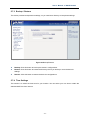
5.7.7 System Log
The section is to view the system log. Click the “Refresh” to update the log. Click “Clear” to clear all
shown information. If the log is over 150 records, it will clear them automatically.
Figure 38 System Log
Refresh: Click this button to update the log.
Clear: Click this button to clear the current log.
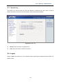
5.8 Logout
Select “Logout” in the left menu if you would like to stop configuring the settings and exit the Web UI of
WNAP-C3220.
- 50 -
User’s Manual of WNAP-C3220
Figure 39 Logout
- 51 -
User’s Manual of WNAP-C3220
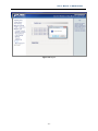
APPENDIX I: WDS Operation Mode Configuration
Bridge (WDS) mode includes P2P, P2MP, and Wireless Repeater.
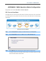
P2P: Point to Point Mode
P2P bridge mode can connect with two wired network via wireless access points, which communicate
by wireless signals and not by cables. This mode can be free from the cable trouble. The P2P topology
shows below:
P2P / PtP: Point to Point Mode
Step 1.
Click the Setup Wizard to configure your WNAP-C3220 to act as Bridge(WDS).
Step 2.
Select Bridge (WDS), and then click Next to enter the Basic Settings page.
Step 3.
Select WDS P2P mode in drop-down list of WDS mode as the picture below:
This page includes the AP and WDS parameter setting. AP parameter setting can change
SSID and enable/ disable wireless feature.
- 52 -
User’s Manual of WNAP-C3220
Object
Description
AP MAC
Enter the interconnection equipment’s MAC address.
Channel
Select the channel according to interconnection equipment’s; the
devices on the two ends must be at the same channel.
Open Scan
Click this button, the AP will scan the nearby wireless devices
automatically and display the information in the table.
Select the device which need to bridge, the AP will add the device’s
MAC address automatically and select the corresponding channel.
Figure 4040 WDS-P2P mode
Step 4.
After finish the setting, click Next to enter Security Settings page, shown in Chapter 5.3.1
- 53 -
User’s Manual of WNAP-C3220
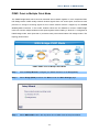
P2MP: Point to Multiple Point Mode
The P2MP Bridge Mode which connects scattered wired network together is more complicated than
P2P Bridge mode. P2MP usually transmit wireless signals from one access point, and other access
points are in charge of receiving signals so as to share network resource. Support up to 4 remote
access point connection. In this mode, wireless clients are not allowed to connect. P2MP Bridge
mode can connect multiple wireless access point together without cabling. If “Root AP” is configured as
P2MP bridge mode, other (less than 4) remote access points should select P2P bridge modes. The
topology shows below:
P2MP / PtMP: Point to Multiple Point Mode
Step 1.
Click the Setup Wizard to configure your WNAP-C3220 to act as Bridge(WDS).
Step 2.
Select Bridge (WDS), and then click Next to enter the Basic Settings page.
Step 3.
Select WDS P2MP mode in the drop-down box of WDS mode as the picture below.
- 54 -
User’s Manual of WNAP-C3220
Configure the following fields before enter to the Next page.
Object
Description
AP MAC Address
Input the remote AP’s MAC address. (No more than 4)
Channel
Select the channel which bridge needs to use.
(All APs in the bridge must be at the same channel.)
Enable Scan
1.
Click this button, the AP will scan the nearby wireless devices
automatically and display the information in the table.
2.
Select the device which need to bridge, the AP will add the
device’s
MAC
address
automatically
and
select
the
corresponding channel.
3.
When multiple devices are added, AP will select the channel of the
last added device as the bridge used channel.
(You can also change the channel according to your need. All the
devices must at the same channel, thus the bridge can be
established.)
Step 4.
After finish the setting, click Next to enter Security Settings page, shown in Chapter 5.3.1.
- 55 -
User’s Manual of WNAP-C3220
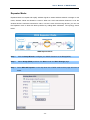
Repeater Mode:
Repeater Mode can repeat and amplify wireless signals to extend wireless network coverage. In this
mode, wireless clients are allowed to connect. When two LAN’s transmission distance is over the
wireless device’s maximum transmission value, or there is much block among devices, you can use
the Repeater mode to deal with these problems by adding MAC addresses. The topology shows
below:
WDS Repeater Mode
Step 1.
Click the Setup Wizard to configure your WNAP-C3220 to act as Bridge(WDS).
Step 2.
Select Bridge (WDS), and then click Next to enter the Basic Settings page.
Step 3. Select WDS AP Repeater on the drop-down box of WDS mode and the page will show as
below.
- 56 -
User’s Manual of WNAP-C3220
Step 4. When the users select “Allow wireless client to access”, AP can also be used as “Wireless
Access Point” to allow the access of wireless client when it is used as a wireless bridge.
The basic settings of wireless repeater are divided into two parts:
One part is the basic setting in AP mode (See 4.1.1.2)
Another part is the basic setting in WDS mode (See 4.1.2.2)
Step 5.
After finish the setting, click Next to enter Security Settings page, shown in Chapter 5.3.1.
- 57 -
User’s Manual of WNAP-C3220
APPENDIX II:Product Specification
Product
WNAP-C3220
300Mbps 802.11n Wireless Ceiling Mount Access Point
Hardware Specification
Standard support
PoE
Interface
Antenna
LED
Button
Power Requirements
Power Consumption
IEEE 802.11b/g
IEEE 802.11n
IEEE 802.3 10Base-T
IEEE 802.3u 100Base-TX
IEEE 802.3ab 1000Base-T
IEEE 802.3x Flow Control
IEEE 802.3af Power over Ethernet
802.3af PoE
Wireless IEEE 802.11b/g/n
LAN: 1x 10/100/1000Base-T, Auto-MDI/MDIX, 802.3af PoE compliant
Built-in 2T2R, 2dbi Printed Antenna
Wireless / Power LED
Reset
Power Supply: DC 12V, 1A
Power over Ethernet: IEEE 802.3af PoE, DC 48V, 0.35A
≦ 6W
Wireless Interface Specification
Frequency Band
Modulation
2.4~2.4835GHz
Transmission/Emission Type: DSSS / OFDM
Data modulation type: OFDM: BPSK, QPSK, 16-QAM, 64-QAM, DBPSK,
DQPSK, CCK
America/ FCC: 2.412~2.462GHz (1~11 Channels)
Opt. Channel
Europe/ ETSI: 2.412~2.472GHz (1~13 Channels)
Japan/ TELEC: 2.412~2.484GHz (1~14 Channels)
RF Output Power
Receiver Sensitivity
TX Power
20dBm (Max.)
IEEE 802.11b: -92dBm @ 1Mbps; -85dBm @ 11Mbps, PER < 8%
IEEE 802.11g: -88dBm @ 6Mbps; -73dBm @ 54Mbps, PER <10%
IEEE 802.11n: -90dBm @ MCS8; -70dBm @ MCS15, PER <10%
User defined (Range 1~100, default 100)
IEEE 802.11b: 1/ 2/ 5.5/ 11Mbps
IEEE 802.11g: 6/ 9/ 12/ 18/ 24/ 36/ 48/ 54Mbps
IEEE 802.11n:
Data Rate
Guard Interval 800ns
Guard Interval 400ns
MCS
20MHz(Mbps) 40MHz(Mbps) 20MHz(Mbps) 40MHz(Mbps)
0
6.5
13.5
7.2
15
1
13
27
14.4
30
- 58 -
User’s Manual of WNAP-C3220
2
19.5
40.5
21.7
45
3
26
54
28.9
60
4
39
81
43.3
90
5
52
108
57.8
120
6
58.5
121.5
65
135
7
65
135
72.2
157.5
8
13
27
14.4
30
9
26
54
28.9
60
10
39
81
43.3
90
11
52
108
57.8
120
12
78
162
86.7
180
13
104
216
115.6
240
14
117
243
130
270
15
130
270
144.4
300
Wireless Management Features
Operating Mode
Encryption Security
Wireless Isolation
Wireless Security
Wireless Client Max.
WMM
BG Protection Mode
APSD
Max. WDS AP
Max. Wired Client
Management
LAN
AP
Repeater
WDS PtP
WDS PtMP
64/128-bits WEP
WPA, WPA-PSK
WPA2, WPA2-PSK
802.1X
Enable it to isolate each connected wireless clients, to let them cannot
access mutually.
Wireless MAC address filtering (up to 50 entries)
SSID broadcast and Hide
20 (default 10)
Wi-Fi Multimedia for better data transmission of Video or on-line demand
A protection mechanism prevents collisions among 802.11b/g modes
For auto power-saved service
4
Unlimited
Static IP, Dynamic IP
Web UI
Management Interface
SNMPv1/v2c
MIB I
SNMP MIB
MIB II (RFC-1213)
Diagnostic tool
System Log
Environment & Certification
Operation Temp.
Temp.: 0~40°c, Humidity: 10%~90% non-condensing
- 59 -
User’s Manual of WNAP-C3220
Storage Temp.
Regulatory
Temp.: -40~70°c, Humidity: 5%~90% non-condensing
CE/RoHS
- 60 -
EC Declaration of Conformity
For the following equipment:
*Type of Product:
*Model Number:
802.11n Wireless Ceiling Mount Access Point
WNAP-C3220
* Produced by:
Manufacturer‘s Name :
Manufacturer‘s Address:
Planet Technology Corp.
10F., No.96, Minquan Rd., Xindian Dist.,
New Taipei City 231, Taiwan (R.O.C.)
is herewith confirmed to comply with the requirements set out in the Council Directive on the
Approximation of the Laws of the Member States relating to 1999/5/EC R&TTE.
For the evaluation regarding the R&TTE the following standards were applied:
EN 300 328
V1.7.1
EN 301 489-17 V2.1.1
EN 301 489-1 V1.8.1
EN 50385
EN 60950-1
(2006-10)
(2009-05)
(2008-04)
(2002)
(2006 + A11 : 2009)
Responsible for marking this declaration if the:
⌧ Manufacturer
Authorized representative established within the EU
Authorized representative established within the EU (if applicable):
Company Name:
Planet Technology Corp.
Company Address:
10F., No.96, Minquan Rd., Xindian Dist., New Taipei City 231, Taiwan (R.O.C.)
Person responsible for making this declaration
Name, Surname
Kent Kang
Position / Title :
Product Manager
Taiwan
Place
15 April, 2011
Date
Legal Signature
PLANET TECHNOLOGY CORPORATION
e-mail: [email protected]
http://www.planet.com.tw
10F., No.96, Minquan Rd., Xindian Dist., New Taipei City, Taiwan, R.O.C.
Tel:886-2-2219-9518 Fax:886-2-2219-9528