1
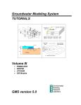
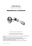
Geotech Sipper Pump & Skimmer Assembly Installation and Operation Manual Rev 01/05/15 Part # 16550181 TABLE OF CONTENTS Section 1: System Description ........................................................................................................... 3 Function and Theory .......................................................................................................................... 3 Specific Gravity and Viscosity Limitations .......................................................................................... 5 Stainless Steel Pump Assembly......................................................................................................... 6 Skimmer Attachments ........................................................................................................................ 7 Heavy Oil Skimmer Attachment ......................................................................................................... 8 High Temperature, Heavy Oil Skimmer Attachment ........................................................................... 8 Section 2: System Installation .......................................................................................................... 10 Section 3: System Operation ............................................................................................................ 11 Section 4: System Maintenance........................................................................................................ 12 Cleaning the Skimmer and Intake Screen ........................................................................................ 14 Conditioning the Intake Screen ........................................................................................................ 14 Section 5: System Troubleshooting ................................................................................................. 15 Section 6: System Specifications ..................................................................................................... 17 Stainless Steel Pump ....................................................................................................................... 17 Stainless Steel Pump with H20 Sensor ............................................................................................ 17 2” Skimmer Assembly ...................................................................................................................... 17 4” Skimmer Assembly ...................................................................................................................... 17 4” Heavy Oil Skimmer Assembly ...................................................................................................... 18 4” High Temperature, Heavy Oil Skimmer Assembly ....................................................................... 18 Section 7: System Schematics ......................................................................................................... 19 Section 8: Parts and Accessories..................................................................................................... 21 The Warranty ...................................................................................................................................... 33 1 DOCUMENTATION CONVENTIONS This document uses the following conventions to present information: An exclamation point icon indicates a WARNING of a situation or condition that could lead to personal injury or death. You should not proceed until you read and thoroughly understand the WARNING message. WARNING A raised hand icon indicates CAUTION information that relates to a situation or condition that could lead to equipment malfunction or damage. You should not proceed until you read and thoroughly understand the CAUTION message. CAUTION A note icon indicates NOTE information. Notes provide additional or supplementary information about an activity or concept. NOTE 2 Section 1: System Description Function and Theory The Geotech Pump and Skimmer assembly (Skimmer), when used in conjunction with the Geotech Sipper Controller, is designed to efficiently collect free-floating hydrocarbons in 2” (5 cm) or larger recovery wells. The system consists of a Solar or AC Sipper controller, a stainless steel pump assembly, an attached Skimmer with floating intake cartridge (or buoy), and a Tankfull probe. The Sipper controller regulates, or cycles, the pump and Skimmer assembly with three timer settings (vacuum, pressure, and delay) which vary the cycle time and recovery rate of the Skimmer. See the Geotech Sipper User Manual for more details on Sipper operation. Timed vacuum and pressure is applied to the pump to draw product from the Skimmer attachment, which is then discharged into an optional above ground recovery tank. The standard Skimmer features a unique product intake assembly that incorporates both a density float and an oleophilic/ hydrophobic membrane that differentiates between floating hydrocarbons and water. The intake assembly follows the water table fluctuations and places the screen at the water/product interface, skimming LNAPL (light, non-aqueous phase liquid) down to a sheen within the range of the float travel. As the system cycles, product is drawn through the intake screen and is transferred to the pump through a coiled hose and the Skimmer’s transfer shaft. Optional heavy oil and high temperature Skimmers, using intake buoys, are also available to recover product in 4” (10 cm) diameter and larger wells. The stainless steel pump is primarily an air driven reservoir with upper and lower check valves. The pump is designed to provide a two-phase pumping cycle. During the first phase, or pump intake phase, vacuum is applied to the pump. This vacuum closes the top discharge check valve while opening the bottom, intake check valve, causing product to be drawn through the Skimmer intake screen and into the pump reservoir. During the second phase, or pump discharge phase, the same air line is pressurized with air. This action closes the bottom, intake check valve on the pump and opens the discharge check valve, forcing the recovered product from the pump reservoir, into the product discharge line, up to the surface, and eventually into a recovery tank. See Figure 1-2 for an example of a typical stainless steel pump cycle. Figure 1-1: Example of a downwell pump assembly 3 Figure 1-2: Typical Product Recovery Cycle in Stainless Steel pump The stainless steel pump can be equipped with an optional Water (H2O) Sensor, which minimizes water intake by immediately purging the pump when water is present in the stainless steel housing. See Section 3: System Operation for more details. 4 Specific Gravity and Viscosity Limitations of Skimmer The specific gravity of the product to be recovered with a Skimmer must be less than 1.0 and its viscosity less than 50 SSU for use with the “light” oil membrane, and 400 SSU for use with the “heavy” oil membrane cartridge. Geotech application engineers may be consulted for product recovery operations with viscosities outside that range. See Geotech Manual, “Hydrocarbon Viscosity Test Kit” for more information on choosing the correct intake membrane. This type of membrane technology is designed to be used in wells with free product of at least 1/8” (3 mm) thickness. The presence of surfactants or detergents in the product requires careful application. Surfactants and detergents may interfere with oil/water interface surface tension. This may interfere with pumping product layers of less than 1/8” as the oil water interface may become mixed. *The system will continue to operate and pump oil/water mixtures. When confronted with these contaminants please consult Geotech. *If using water sensor in stainless steep pump, the sensor may need to be temporarily removed/disconnected to allow oil/water mix to be pumped. Other Applications for Stainless Steel Pump The typical configuration of Stainless Steel Pump with attached Skimmer is implemented when floating hydrocarbons with density less than 1, or water, are pumped. Without the Skimmer, the stainless steel pump can be used either as a stand alone total fluids pump or a DNAPL recovery pump. DNAPL or Dense Non Aqueous Liquids, are liquids that have a specific gravity greater than 1, or water. Sources of DNAPL contamination are typically chlorinated solvents leaked from industrial processing and storage. DNAPL is particularly difficult to find in free phase in ground water aquifers. Typically when free phase DNAPL is found it is at a solid rock barrier or a very low permeability material, such as tight clay. In either case the recharge rate of the free phase DNALP layer at the bottom of a recovery well will typically be slow. The stainless steel pump, when equipped with a Water Sensor and a screened intake is an effective way of pumping DNAPL. The water sensor will reduce the amount of non-DNAPL (water) pumped, and the screen intake will ensure proper operation of the pump’s check valves in a potentially gritting environment. See Figure 1-3 for a DNAPL pumping configuration. The system can be easily changed in the field from DNAPL recovery to a total fluid system by simply disconnecting the water sensing system. Follow Skimmer attachment guidelines when connecting the DNAPL intake, see Section 2: System Installation. Figure 1-3: DNAPL recovery configuration for Stainless Steel Pump 5 System Components Stainless Steel Pump Assembly An air operated stainless steel pump is attached to the upper portion of the Skimmer. The pump consists of a stainless steel outer housing with top and bottom check valves. Figure 1-4: Stainless Steel Pump Assembly 6 Skimmer Attachments A standard Skimmer attachment (when connected to the stainless steel pump assembly) is designed for use in either 2” (5 cm) diameter wells or 4” (10 cm) diameter and larger wells. Figure 1-5 shows an example of the two most common Geotech Skimmers. These Skimmers come with a standard 100 mesh intake screen. A 60 mesh intake screen is also available for use with higher viscosity fluids. See Geotech Manual “Hydrocarbon Viscosity Test Kit” for more information on choosing the correct intake cartridge. Figure 1-5: Standard 2” and 4” Skimmer Attachments 7 The Skimmer assembly is connected to the bottom of the stainless steel pump with a 6” piece of durable, fuel grade hose. The Skimmer consists of a product intake float, a coiled product transfer hose, and a transfer shaft. Well centralizers are placed at the top and bottom of the Skimmer shaft to protect the intake float and to allow unobstructed travel within the well. Standard Skimmers can provide 12” (30 cm) to 24” (61 cm) of intake travel. Geotech can provide up to 5’ (1.5 m) of travel (4” Skimmers only) on a custom order basis. A Skimmer assembly will not draw water unless the intake cartridge is forcibly submerged, surfactants are present, or when the “conditioning” of the intake screen has been removed. See Section 4 for information on reconditioning the intake screen. Heavy Oil Skimmer Attachment The optional heavy oil Skimmer attachment is designed to recover a range of fluids from gasoline to gear oil, skimming the product down to .01 feet (3 mm) in 4” (10 cm) diameter and larger wells. This option is best suited when the viscosity of the hydrocarbon is greater than the capability of the membrane screen technology (screen can no longer pass the hydrocarbon fluid). The heavy oil Skimmer consists of a polypropylene intake buoy, a coiled product transfer hose, and a transfer shaft with well centralizers placed at the top and bottom. The intake buoy on the heavy oil Skimmer is designed to “ride” at the oil water interface and has a travel range of 24” (61 cm). This assembly is ideal for use where the oil/water interface is broken down by detergents or is emulsified. The intake buoy can also be “fine-tuned” by adjusting the intake fitting on the top of the buoy. Turning the fitting clockwise will lower the intake fitting relative to the product/water interface. Turning the fitting counter-clockwise will raise the intake fitting away from the interface. Figure 1-6 is an example of a heavy oil Skimmer assembly. Figure 1-6: Heavy Oil Skimmer Attachment (optional) 8 High Temperature, Heavy Oil/Aggressive Chemical Skimmer Attachment For high temperature well environments, Geotech provides a high temperature, heavy oil (HTHO) Skimmer that incorporates an ultra high molecular weight (UHMW) polyethylene intake buoy. The HTHO Skimmer has stainless steel end caps placed at the top and bottom of a stainless steel screen to keep out debris. The intake buoy of the HTHO Skimmer has a travel range of 26” (66 cm). Like the heavy oil Skimmer, the intake buoy can be “fine tuned” by adjusting the intake fitting on the top of the buoy. Turning the fitting clockwise will lower the intake fitting relative to the product/water interface. Turning the fitting counter-clockwise will raise the intake fitting away from the interface. Figure 1-7 is an example of the high temperature, heavy oil Skimmer. Figure 1-7: High Temp, Heavy Oil Skimmer Attachment (optional) 9 Section 2: System Installation Prior to installation, ensure that the intake screen is “conditioned” (or primed, with diesel fuel or a similar hydrocarbon.) The optimum fluid would be to use the same downwell hydrocarbon to be recovered. Use a soft, bristle brush to avoid damaging the screen intake. Install well cap as per manufacturors guidelines. Calculate the tubing lengths required to install the Skimmer. Normal tubing lengths are around 180’ (55 m) in well depth, suggested maximum is around 500’ (152 m) total system length. Longer systems can be accomidated if care is taken to protect tubing and account for longer cycle timers. To calculate the amount of air line and discharge hose required to suspend the pump and Skimmer in the well, first determine the following lengths: Measure the static water depth in the well using a Geotech Interface Probe. Measure the distance between the wellhead and the Sipper controller. Measure the distance between the wellhead and the product recovery tank. See Figure 2-1 for a view of the Skimmer in relation to the well cap and static water level. Do not make any cuts to the tubing until all measurements, between the controller and wellhead, and from the wellhead to recovery tank have been made. If need be, attach the Skimmer or intake to the bottom of the stainless steel pump using the 6” (15 cm) piece of rubber fuel hose and hose clamps provided. Ensure both ends of the hose are placed as far as they can go on each hose barb and then tighten the hose clamps in place. Check connection by gently tugging at each hosebarb. The tubing should be secure. Figure 2-1: Connection between stainless steel pump and intake This hose connection is important. An old or brittle piece of fuel hose or a loose hose clamp between the pump and Skimmer could eventually cause the Skimmer to detach and fall into the well. Always inspect this connection prior to use. 10 Pull the measured lengths of air line and discharge hose through the fittings on the well cap (when applicable). Fully tighten the compression fittings around the hose and tubing at the well cap. The well cap is designed to suspend the pump and Skimmer assembly by the sturdier discharge hose. For system over 50’ in well depth, a safety cable is highly suggested. Attach the air line and discharge hose to the pump and Skimmer assembly with hose clamps. After attaching the needed lengths of tubing, place the pump and Skimmer assembly into the well so that the midpoint of the intake float travel lies on the static water level measured. Connect the air line from the pump to the Sipper controller. Connect the product discharge hose from the pump to the product recovery tank. Ensure that both lines are kept level and that there are no kinks or sags in the lines. When possible, enclose the lines within a secondary pipe or conduit to protect them from damage. Install the Tankfull probe in the recovery tank and connect the probe connector to the Sipper controller. Figure 2-2: Pump and Skimmer Assembly with generalized Well Cap 11 Section 3: System Operation The stainless steel pump assembly with Skimmer is designed to operate with the Geotech Sipper Controller. After all connections have been made, set the vacuum, pressure, and delay times for the pump and allow the unit to run. Make any needed adjustments to the timing before leaving the system. Read the Geotech Sipper User Manual (P/N 16550176) in conjunction with this manual to establish the operational requirements of your Sipper system. The stainless steel pump can be equipped with an optional H2O sensor. Figure 3-1 is an example of a typical stainless steel pump cycle when water is sensed and then purged: Figure 3-1: Active H2O Sensor Cycle in Stainless Steel Pump The amount of water purged/pumped is minimal, <10mL, relative to the stainless steel pump’s internal volume, which is around 200mL. 12 Section 4: System Maintenance Always ensure all hose and tubing fittings at the pump and between the pump and Skimmer are tight prior to deploying the unit into the well. Monthly (or per Site Visit, at minimum) Maintenance Pull the pump and Skimmer from the well. Inspect all tubing for cracks, kinks and damage. Replace any old and brittle tubing. Inspect the coiled tubing for physical damage or obstructions. Verify the intake assembly moves freely over its travel range. Inspect the float (buoy) and intake screen. Clean the intake screen and float using the method described in this section. Inspect the Skimmer assembly for signs of physical damage. Scrapes or dents in the screen intake may cause the Skimmer to take on water. If such damage is found, a new 2” or 4” intake assembly may be necessary. Clear away any debris collected in the well vault (or above ground casement). Measure the well and record product layer thickness and depth to water from top of well casing. Verify pump vacuum, pressure, and delay settings are adjusted for the recharge rate of the well. Place a pump positioning mark or zip tie on the discharge hose (usually black) even with the top of well casing. Re-deploy pump, aligning new depth to water mark on discharge hose with top of well casing. Check the Tankfull probe for proper operation. Quarterly Maintenance Pull pump and Skimmer. Clean the well screen (site specific, primarily to clear bio growth and keep thick degraded product from impeding conductivity to the well at the product layer. Frequency to be determined by user.) Place float assembly in water to verify the screen stays out of the water at the top of the traverse range. If it does not, replace the coiled tubing and retest. If it still does not, replace the float assembly. Yearly Maintenance Pull the pump and Skimmer from the well. Open pump and clean interior and parts with soapy water. Degrease the check disk and check ball seats. Spray with WD40 or kerosene. Clean and prime intake screen using the method described in this section. 13 Cleaning the Skimmer and Intake Screen Standard 2” and 4” Skimmers will usually come with a float containing a 100 or 60 mesh intake screen. When required, gently clean the screen with WD40 or kerosene, using a soft, bristle brush, to remove emulsified product, bio growth or other debris. Take care to avoid damaging the screen intake. Rinse the product intake assembly with clean water and make sure it is completely dry before reconditioning the intake screen. For heavy oil Skimmers, use warm soapy water first, followed by WD40 or kerosene to remove debris or bio growth from the buoy body, then rinse and let dry. Using warm soapy water, clean all debris and bio growth from the Skimmer shaft and coiled tubing. Conditioning the Skimmer Intake Screen Prior to initial deployment, and after every cleaning, the intake screen must be conditioned (or primed) with diesel fuel or other similar hydrocarbon. Use a soft, bristle brush to saturate the screen portion of the intake thoroughly. The optimum fluid would be to use the downwell hydrocarbons being recovered. Take care to avoid damaging the screen intake. 14 Section 5: System Troubleshooting Additional troubleshooting measures can be found in the Solar Sipper User Manual. Problem: The pump is only discharging water, not product. Solutions: The water level has risen above the travel range of the Skimmer. Pull the pump and Skimmer out of the well. Purge the water out of the intake and pump by allowing the system to cycle for several minutes, prime the intake cartridge screen, then reset the Sipper controller. The pump position has slipped, or the pump was installed below the water level in the well. Prime the intake cartridge screen , re-position the pump and Skimmer, then reset the Sipper controller. The intake assembly will not slide freely, or the coiled hose is tangled. Inspect the Skimmer assembly and repair as necessary. Loose hose or tubing on fittings below intake level. Check all fitting connections. Problem: The pump discharges air only, no product. Solutions: Product has been removed. Recalculate and reduce the pumping rate at the Sipper controller. The Product layer is below the bottom of the Skimmer's travel range. Adjust the position of the Skimmer assembly within the well and then reset the Sipper controller. The Skimmer assembly has detached from the pump (due to a cut hose or loose hose clamp.) If the Skimmer assembly cannot be “fished” from the well then a new Skimmer will be needed. 15 Problem: The pump cycles but does not discharge product. Solutions: One or both of the pump check valves are malfunctioning. Remove and clean pump assembly from particulates, or replace check valve components. The viscosity of the product is too thick for the Skimmer. Contact Geotech to discuss other Skimmer options for the type of product in the well. The intake screen is obstructed or the coiled hose is kinked. Verify that the intake is clean of debris and bio growth Check the condition of the coiled hose. Problem: The pump does not operate. Solutions: The product recovery tank is full. Empty the recovery tank, inspect the Tankfull probe float and then restart the Sipper controller. The intake float switch is high. Drain the intake float switch assembly (on the side of the controller) and inspect all lines and solenoids for fluid vacuumed into the controller. Blow out all lines and parts, adjust vacuum timing and then restart the Sipper controller. Problem: Applicable if pump is equipped with optional H2O Sensor: pump is having to purge water with every cycle. Solutions: The skimmer is submerged in water. The product layer has been fully recovered or the water table has raised beyond the skimmer’s travel capabilities. Reset the pump position so that the intake screen and top of the hydrocarbon layer is in the middle of the skimmer’s travel distance. 16 Section 6: System Specifications Application: Recovery Rate: Maximum Depth Maximum Pressure: Oil/Water Separation: 2” (5 cm) or larger recovery wells .2 gallons (.76 liters) per cycle 180 feet (54.9 m) 100 PSIG (6.9 bar) Oleophilic/hydrophobic mesh screen Stainless Steel Pump Size: Weight: Materials: Air Line: Discharge Line: 23.5”L x 1.75” OD (59.7 cm L x 4.5 cm OD) 4.5 lbs. (2 kg) 303 and 304 SS, flexible tubing, PVC, and Brass .170” ID x .25” OD (Polyethylene) .375” ID x .5” OD (Polyethylene or fuel grade Synthetic Rubber) Stainless Steel Pump with H20 Sensor Size: Weight: Materials: Air Line: Discharge Line: H2O Sensor cable: 23.5”L x 1.75” OD (59.7 cm L x 4.5 cm OD) 5 lbs. (2 kg) 303 and 304 SS, flexible tubing, PVC, and Brass .170” ID x .25” OD (Polyethylene) .375” ID x .5” OD (Polyethylene or fuel grade Synthetic Rubber) Polyurethane insulated cable (28AWG), Acetal Resin 2” Skimmer Assembly Size: Weight: Materials: Effective Travel: Operating Temperature: 35.5” L x1.75” OD (90 cm L x 4.5 cm OD) 1.75 lbs. (0.8 kg) 304 SS, Polyethylene, PVC, Polypropylene, and Brass Fittings 12” (30.5 cm) Standard Travel 32º to 100º F (0° to 38° C) Minimum fluid level to activate Skimmer = 15” (38 cm) 4” Skimmer Assembly Size: Weight: Materials: Effective Travel: Operating Temperature: 35.5” L x 3.75” OD (90 cm L x 9.5 cm OD) 2.25 lbs. (1 kg) 304 SS, Polyethylene, PVC, Polypropylene, and Brass Fittings 24” (61 cm) Standard Travel, up to 5 feet (1.5 m) available 32º to 100º F (0° to 38° C) Minimum fluid level to activate Skimmer = 9” (23 cm) 17 4” Heavy Oil Skimmer Assembly Size: Weight: Materials: Effective Travel: Operating Temperature: 40” L x 3.75” OD (102 cm L x 9.5 cm OD) 2.5 lbs. (1.1 kg) 304 SS, PP, and Brass Fittings 24” (61 cm) Standard Travel 32º to 100º F (0° to 38° C) Minimum fluid level to activate Skimmer = 15” (38 cm) 4” High Temperature, Heavy Oil Skimmer Assembly Size: Weight: Materials: Effective Travel: Operating Temperature: 40” L x 3.75” OD (102 cm L x 9.5 cm OD) 2.5 lbs. (1.1 kg) 304 SS, HDPE, and Brass Fittings 24” (61 cm) Standard Travel 32º to 212º F (0° to 100° C) Minimum fluid level to activate Skimmer = 15” (38 cm) 18 Section 7: System Schematics Figure 7-1: Stainless Steel Pump with Skimmer Dimensions 19 Note: Optional H2O Sensor on Stainless Steel Sipper Pump does not affect overall dimensions Figure 7-2 – Standard Pump and Skimmer Dimensions 20 Section 8: Parts and Accessories Figure 8-1: Stainless Steel Pump Assembly 21 Sipper Stainless Steel Pump Assembly (56600050) Item # Parts Description Parts List 1 2 3 4 5 6 7 8 9 10 11 12 13 14 15 16 O-RING,VITON,#128 HOUSING,SS,PUMP,CRS/PRS CAP,TOP,SS,CRS TUBE,CONN,1/4X1/8MPT,POLYTITE PUMP NIPPLE,BRS,HEX,1/8NPT VALVE,CHECK,PRODUCT DISCHARGE CRS/PRS PUMP HOSEBARB,BRS,3/8"X1/8MPT DISC,PVC,CHECK CAP,SS,BOTTOM,CRS/PRS HOSEBARB,BRS,3/8"X1/4MPT O-RING,VITON,#208 PIN,SS,DOWEL,CHK DISK CRS/PRS CLAMP,SS,STEPLESS EAR,17MM TUBING,RBR,3/8x5/8,FT PRODUCT DISHCARGE CLAMP,SS6,WORM,7/32-5/8" TUBE,INTERNAL,SIPPER PUMP 16600030 26600013 26600019 16600037 17500151 26600157 16650310 26600017 26600018 16650323 16600023 26600162 16600004 16600019 16600063 26600170 22 Figure 8-2: Stainless Steel Pump Assembly with optional H2O Sensor Sipper Stainless Steel Pump with optional H2O Sensor Assembly* (56600059) In addition to previously listed parts for Sipper Stainless Steel Pump Assembly (56600050): - *SENSOR, H2O, REPLACEMENT CABLE, 28AWG, 8COND, URETH CLAMP,INSULATOR,PRS, W/H2O SENSOR SCREW,SS6,6-32x.75",PNH *Requires specified cable length, maximum 500ft 23 56600085 ORS418005 26600270 PPF013012 Figure 8-3: Standard 2” Skimmer Assembly 24 2” Skimmer Assembly – 100 mesh (56600003) Item # Parts Description Parts List 1 2 3 4 5 6 7 8 9 CLAMP,SS,STEPLESS EAR,7MM HOSE,COILED,PR2 HOSEBARB,BRS,3/8"X1/8FPT CENTRALIZER,PVC,SKIMMER,2" SHAFT,SS,SKIMMER,33.5",PRC CAP,BRS,1/8FPTx10-32 90 DEG HOSEBARB,BRS,1/8"X10-32,90DEG ASSY,BUOY,SKIMMER,2"100MESH HOSE CLIP,SKIMMER FLOAT 16600005 26650304 16650308 26650306 26600002 16600064 17500149 56650309 26650028 2" Skimmer Options 8 10 11 ASSY,BUOY,SKIMMER,2" 60 MESH CENTRALIZER,PVC,SCREENED PR2 SCREEN,SS,1.88"ODX32.7" STRAIGHT WELD 56650312 26600186 26600188 Additional 2" Skimmers HOUSING,RECLAIMER,1.66,SS4,36" ASSY,SKIMMER,2",60 MESH ASSY,SKIMMER,2",60M,W/SCREEN 25 56600064 56600069 56600071 Figure 8-4: Standard 4” Skimmer Assembly 26 4” Skimmer Assembly – 100 mesh (56600004) Item # Parts Description Parts List 1 2 3 4 5 6 7 8 9 CLAMP,SS,STEPLESS EAR,7MM HOSE,COILED,PR4 HOSEBARB,BRS,3/8"X1/8FPT CENTRALIZER,SKIMMER,PR4 SHAFT,SS,SKIMMER,33.5",PRC CAP,BRS,1/8FPTx10-32 90 DEG HOSEBARB,BRS,1/8"X10-32,90DEG ASSY,BUOY,SKIMMER,4"100 MESH HOSE CLIP,SKIMMER FLOAT 16600005 16650312 16650308 16600048 26600002 16600064 17500149 56650310 26650028 4" Skimmer Options 8 10 11 ASSY,BUOY,SKIMMER,4" 60 MESH CENTRALIZER,PVC,SCREENED PR4 SCREEN,SS,3.67" DIAM X32.7" 56650313 26600187 26600189 Additional 4" Skimmers ASSY,SKIMMER,4",100M,W/SCREEN ASSY,SKIMMER,4",100 MESH,5 FT EXTENDED TRAVEL ASSY,SKIMMER,4",60 MESH ASSY,SKIMMER,4",60M,W/SCREEN ASSY,SKIMMER,4",60 MESH,5 FT EXTENDED TRAVEL 27 56600055 56600008 56600070 56600072 56600073 Figure 8-5: 4” Heavy Oil Skimmer Assembly 28 4” Heavy Oil Skimmer (56600005) Item # Parts Description Parts List 1 2 3 4 5 6 7 8 9 BUOY,PP,HEAVY OIL FTG,INTAKE,OIL BOUY HOSEBARB,BRS,.170"X1/8MPT,90D HOSEBARB,BRS,3/8"X1/8FPT CENTRALIZER,SKIMMER,PR4 SHAFT,SS,OIL SKIMMER,38" HOSE,COILED,OIL SKIMMER CLAMP,SS,DBL PINCH,9/32-23/64" COUPLING,SS4,.125" 26600004 26600005 17500148 16650308 16600048 26600006 26600007 11200273 16600006 4" Heavy Oil Skimmer Options ASSY,BUOY,OIL SKIMMER,4" 56600060 29 Figure 8-6: 4” High Temperature, Heavy Oil Skimmer Assembly 30 4”, High Temp, Heavy Oil Skimmer (56600012) Item # Parts Description Parts List 1 2 3 4 5 6 7 8 9 BUOY,UHMW,HEAVY OIL,HI-TEMP FITTING,BUOY INTAKE,HTHO HOSEBARB,BRS,1/8"X10-32,90DEG HOSEBARB,EXT,1/8M/F NPT,10-32 END CAP,BUOY INTAKE,HTHO TUBING, COILED, PTFE, HTHO SKIMMER,SHROUD,4",HTHO PIPE,CENTERING,SCH80,1/8",HTHO FITTING,HEX CAP,1/8FPT,HTHO 26600206 26600207 17500149 27200012 26600209 56600074 26600210 27500005 27200013 Sipper and Skimmer Accessories Parts Description Parts List MANUAL, SIPPER PUMP & SKIMMER ASSEMBLY MANUAL, SOLAR SIPPER MANUAL,TEST KIT,HYDROCARBON VISCOSITY TEST KIT,HYDROCARBON VISCOSITY 16550181 16550176 26030001 86020001 WELL CAP,2",SLIP W/ CMPRSN FTG SIPPER WELL CAP,4",SLIP W/ CMPRSN FTG SIPPER 86600061 86600062 TUBING,PE,.170x1/4,FT POLYETHYLENE TUBING,TLPE,.170x1/4,FT FEP LINED POLYETHYLENE TUBING,FEP,.170x1/4,FT FEP 87050501 87050529 87050509 TUBING,RBR,3/8x5/8,FT PRODUCT DISHCARGE TUBING,TLPE,3/8x1/2,FT FEP LINED POLYETHYLENE TUBING,FEP,3/8x1/2,FT FEP 16600019 87050506 87050511 CLAMP,NYL,1/4" SNAPPER CLAMP,SS,STEPLESS EAR,17MM CLAMP,SS6,WORM,7/32-5/8" 11150259 16600004 16600063 31 EDCF# DOCUMENT REVISIONS DESCRIPTION REV/DATE - Previous Release 06/05/2012 - Updated manual to include PRS with H2O Sensor option – SP 6/12/2014 - Clarify H2O Sensor as optional – SP 9/2/2014 - General updates and clarifications, included DNAPL information – SP, JL 01/05/15 32 The Warranty For a period of one (1) year from date of first sale, product is warranted to be free from defects in materials and workmanship. Geotech agrees to repair or replace, at Geotech’s option, the portion proving defective, or at our option to refund the purchase price thereof. Geotech will have no warranty obligation if the product is subjected to abnormal operating conditions, accident, abuse, misuse, unauthorized modification, alteration, repair, or replacement of wear parts. User assumes all other risk, if any, including the risk of injury, loss, or damage, direct or consequential, arising out of the use, misuse, or inability to use this product. User agrees to use, maintain and install product in accordance with recommendations and instructions. User is responsible for transportation charges connected to the repair or replacement of product under this warranty. Equipment Return Policy A Return Material Authorization number (RMA #) is required prior to return of any equipment to our facilities, please call our 800 number for appropriate location. An RMA # will be issued upon receipt of your request to return equipment, which should include reasons for the return. Your return shipment to us must have this RMA # clearly marked on the outside of the package. Proof of date of purchase is required for processing of all warranty requests. This policy applies to both equipment sales and repair orders. FOR A RETURN MATERIAL AUTHORIZATION, PLEASE CALL OUR SERVICE DEPARTMENT AT 1-800-833-7958. Model Number: ________________ Serial Number: ________________ Date of Purchase: ________________ Equipment Decontamination Prior to return, all equipment must be thoroughly cleaned and decontaminated. Please make note on RMA form, the use of equipment, contaminants equipment was exposed to, and decontamination solutions/methods used. Geotech reserves the right to refuse any equipment not properly decontaminated. Geotech may also choose to decontaminate the equipment for a fee, which will be applied to the repair order invoice. 33 Geotech Environmental Equipment, Inc 2650 East 40th Avenue Denver, Colorado 80205 (303) 320-4764 ● (800) 833-7958 ● FAX (303) 322-7242 email: [email protected] website: www.geotechenv.com