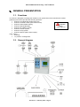
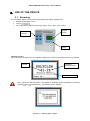
Download POLYCLIM 21A + Timer + Fog
Transcript
POLYCLIM 21A + Timer + Fog User’s Manual POLYCLIM 21A+Timer+Fog – User’s Manual 11.. GENERAL PRESENTATION 1.1. Functions The device is designed to manage the climate in your greenhouses and horticultural or market gardening tunnels and provides the following functions : Control of 2 independent single side vents. Control of a shade curtain (Or thermal screen). installation Control of thermostatic heating. safety Control of dehumidification. (refer to § 5.2) Control of an inflation system. Control of a timer system. Control of a fog system. Control of alarms (With control output). and in option : archiving. « 4 periods » management. 1.2. General diagram Version 3.x – February 2010 – Page 2 POLYCLIM 21A+Timer+Fog – User’s Manual 22.. USE OF THE DEVICE 2.1. Browsing For information display, menu browsing and parameter setting, regulator has: a 28x64 pixel graphic screen 4 keys : 4 five-way selector switches of the type "Open - Stop - Auto - Stop - Close" Graphic screen 4 selector switches 4 keys Start-up screens: When the power is switched on, the regulator displays the version and operating mode. For example : Version Number of managed zones Operating mode Note : During the start-up phase, it is possible to reinitialize all the parameters by pressing the keys and simultaneously. The following screen appears: Version 3.x – February 2010 – Page 3 POLYCLIM 21A+Timer+Fog – User’s Manual then the program options : and the configuration of inputs and sensors present: Input defined and sensor connected Input not defined (not used) Input defined but sensor not connected The followings sensors can be defined: Label on screen Int Temp° Water Temp° Soil Temp° Ext Temp° Int Hygro Ext Hygro Sunniness Luminosity Wind vane CO2 Rain Type of sensor Interior temperature (ambient) Heating water circuit temperature Soil (ground) temperature Exterior temperature Interior hygrometry (ambient) Exterior hygrometry Solar power (Watt/m²) Light intensity (Lux) Wind vane 0/360° CO2 Rain (4/20 mA output) Screen fields and symbols: Display field Alarm symbol Operating symbol Display strip Version 3.x – February 2010 – Page 4 POLYCLIM 21A+Timer+Fog – User’s Manual The display field is used to display all the information for menu browsing, messages, parameter setting, etc. The display strip is used to display the date and time, as well as scrolling messages or information during browsing. The alarm symbol is one of two icons indicating whether or not an alarm is present (current or stored). no alarm alarm present The operating symbol is a moving thermometer showing that the regulator is active. Home screen: After the start-up phase, the regulator displays various screens in alternation, depending on the version and sensors connected (wind speed, solar power, temperature, etc.). For example: Screen saver: To preserve the screen and increase its life, the regulator switches automatically to "saver" mode after a given time. The information disappears, any changes made to the parameters are saved and a small logo moves around the screen: The home screen reappears as soon as a key is pressed. Version 3.x – February 2010 – Page 5 POLYCLIM 21A+Timer+Fog – User’s Manual Icon screen: This icon screen is accessed by pressing any key on the home screen. It is used to open the menus in order to modify parameters, read values, etc. To move around, use the key to go to the right and the key to go to the left. For example: To run the action represented by the icon, press the key To return to the home page, use the key The icons are as follows: access to the "Setpoints" menu (= main setpoints) access to the "Weather" menu (= weather settings) access to the "Alarms" menu (= list of stored alarms) access to the "Readings" menu (= reading of sensors, control status, etc.) access to the "Settings" menu (= setting of parameters other than setpoints) access to the "Installation" menu (= calibration of sensors, maintenance) access to the "Date and Time" menu (= setting of the system date and time) access to the "System" menu (= language setting, etc.) Note : The symbol means that the menu opens after a long press on the icon. Version 3.x – February 2010 – Page 6 POLYCLIM 21A+Timer+Fog – User’s Manual Scrolling menu screens: The scrolling menus are accessed via the icons and are used to choose the parameters to be set from a list with several levels. For example: To move around, use the key to move down and the key to move to up. To run the action shown on the menu (expand or reduce a level, open a parameters menu, etc.) use the key The key can be pressed at any time to return to the previous screen (icons). Parameter menu screens: The parameter menu screens are accessed from the icons or scrolling menus and are used to select a given parameter from a list in order to modify its value. For example: To move around, use the key to move down and the key the selected parameter, use the key to move to up. To access setting of To return to the previous screen at any time, use the key Version 3.x – February 2010 – Page 7 POLYCLIM 21A+Timer+Fog – User’s Manual Parameter setting screen After browsing through the menus and choosing a parameter, it is possible to modify its value. For example: Parameter name Current value Parameter number Minimum value Maximum value To change the value, use the key to increase and the key maximum values indicate the limit values of the parameter. to decrease. The minimum and To validate and save the parameter setting, use the key To cancel the parameter setting and return to the previous screen (parameters menu), use the key Version 3.x – February 2010 – Page 8 POLYCLIM 21A+Timer+Fog – User’s Manual Error or information screens If there is a problem, the regulator displays information screens such as: The regulator cannot read the parameters battery or memory problem The regulator cannot save the parameters memory problem The regulator cannot acknowledge an alarm memory problem or alarm not recognized The regulator cannot create menu or alarm lists memory problem The regulator cannot read the time problem with real-time clock component To solve any problems, proceed as follows in every case: 1. Cut off the power supply for around ten seconds 2. Restore the power to the device 3. Repeat the operation that seems to have caused the problem 4. If the problem persists, contact the retailer of the device. Version 3.x – February 2010 – Page 9 POLYCLIM 21A+Timer+Fog – User’s Manual 2.2. Integrated manual operation Depending on the version, the regulator has: 1, 2, 3 or 4 five-way selector switches of the type "Open - Stop - Auto - Stop - Close" 1 two-way switch of the type "Auto – Override" Five-way selector switches E.g. for the regulator 31 (3 ventilation switches, 1 shade switch) Roof ventilation control Shade curtain control Left-hand side ventilation control Right-hand side ventilation control Type of regulator The various selector switch positions: Manual « Open » Manual « Stop » Automatic Manual « Stop » Manual « Close » The selector acts directly on the regulator outputs. When a selector is set to "Manual" (open, close or stop), the regulator no longer monitors the function concerned (e.g. roof ventilation). On switching back to "Automatic", the regulator automatically resets the function concerned. Version 3.x – February 2010 – Page 10 POLYCLIM 21A+Timer+Fog – User’s Manual Two-way switch The two-way switch is used to control inflation and is located inside the case between the input and output terminal blocks. The various positions of the switch: « On » : Override « Auto » : Automatic The switch acts directly on the R9 output of the regulator. When the switch is set to "Override", the regulator no longer monitors the function concerned (e.g. inflation). On switching back to "Automatic" position, the regulator restarts the inflation cycle on an interval. Version 3.x – February 2010 – Page 11 POLYCLIM 21A+Timer+Fog – User’s Manual 2.3. General Parameters 2.3.1. Date and Time Date and Time Menu WA01 System Time Internal time of the device This is the time used by the device for the various regulation functions WA02 System Date Internal date of the device This is the date used by the device to record events such as alarms WA03 Summer/Winter Auto. Automatic management of the hour summer/winter Allows an automatic adjustment of the hour at the time of the passage of summer to winter (–1h at the end of October) and of winter to summer (+1h at the end of March) 2.3.2. Min : Max : Default : 00.00 23.59 12.00 Min : Max : Default : 01/01/2005 31/12/2099 01/01/2005 Min : Max : Default: NO YES YES Sensor Calibration and Maintenance Mode For each sensor, it is possible to apply a correction to the measurement made by the device. Installation Menu Calibration YA01 Sensor name Min : Max : Default : The title depends on the sensor defined on the analogue input (see start-up screen) The minimum and maximum values change for each type of sensor as shown in the table below Sensor type Temperature Humidity Sunlight Light intensity Wind vane 0/360° CO2 Min -5.0 °C -10 % -100 Watt/m² -1000 Lux -50 ° -100 ppm Max + 5.0 °C + 10 % +100 Watt/m² +1000 Lux +50 ° +100 ppm ON/OFF type sensors cannot be calibrated. For example: Wind speed sensor, 2-sides wind vane, Rain, etc. (measurement correction not possible for these sensors) Version 3.x – February 2010 – Page 12 POLYCLIM 21A+Timer+Fog – User’s Manual The "Maintenance" menu is used only to test the regulator outputs in order to check that the controls (ventilation, heating, etc.) are correctly connected Installation Menu Maintenance When this menu is displayed, all regulation functions are inhibited. ventilation, heating, etc. are no longer monitored in automatic mode. YX01 Output to activate Output that the operator wishes to activate Used to select the output to be activated in maintenance mode (see section "Power supply and output connections). Min : Max : Default : None R12 None The selected output is activated as soon as this menu is displayed after exiting from this menu, the regulator reinitializes all the regulation functions (readjustment of air vents, etc.) and resumes in automatic mode. 2.3.3. System System Menu Settings XA01 Language Language currently used Used to modify the language of all titles XA02 Operating Mode General operating process Allows to activate or not certain adjustments in other menus, in particular related on the weather influences and automatic calculations of the hours of sunrise and sunset XA03 Latitude Latitude of geographic point Min : Max : Default : French Min : Max : Default: SIMPLE EXPERT SIMPLE Min. Max. Default 90° S 90° N 47° N Min. Max. Default 180° W 180° E 0°54’ W (1) Latitude of the site where the regulator is installed intervening in the calculation of the hours of sunrise and sunset XA04 Longitude Longitude of geographic point (1) Longitude of the site where the regulator is installed intervening in the calculation of the hours of sunrise and sunset XA05 GMT Hour GMT Hour (1) Shift compared to GMT hour of the site where the regulator is installed intervening in the calculation of the hours of sunrise and sunset Version 3.x – February 2010 – Page 13 Min. Max. Default -12h +12h +1h POLYCLIM 21A+Timer+Fog – User’s Manual XA06 Winter/Summer time Winter/Summer time Taking automatically into account of Winter/Summer time. (1) Min. Max. Default NO YES YES XA07 Screen Saver Delay Screen saver delay Minimum screen hold time before switching to "screen saver" mode (set a value of 1000 to prevent switching to screen saver mode) Min : Max : Default : 30 s 999 s 600 s XA08 Network Address Address of the regulator on the network Number of the regulator used to network the device with a supervision system. Min : Max : Default : 1 99 1 Notes : Parameter visible (1) If “XA02” is set to “Expert” Version 3.x – February 2010 – Page 14 POLYCLIM 21A+Timer+Fog – User’s Manual System Menu Version & Date Menu in read mode only (no setting) XB01 Polyclim Type Type of regulator Provides information about the type of regulator XB02 Version Version of the regulator Provides information about the regulator program version XB03 Date Date of the regulator Provides information about the date of the regulator program XB04 Configuration Number Configuration Number Provides information about the configuration of the regulator System Menu Input Config. Menu in read mode only (no setting) XC01 Sensor name Indicates whether or not a sensor is present when switching on The parameter number corresponds to the analogue input. For example: XC01 corresponds to input A1, XC01 corresponds to input A2, Etc. System Menu Option Config. Menu in read-only mode (no setting) XD01 Option name Provides information about the options managed by the regulator For example: "Thermostatic heating", "Dehumidification", "Air Mixer", etc. Version 3.x – February 2010 – Page 15 POLYCLIM 21A+Timer+Fog – User’s Manual 33.. FUNCTIONS 3.1. Weather detection 3.1.1. Principle Several safety systems are possible, depending on the sensors connected to the controller. Wind speed The measured wind speed the degree of vent closing. Wind direction o Two directions wind vane A two directions wind vane is sufficient when all compartments and vents of the installation are directed in the same way. The screw of the 2D vane by convention is called the right side. In the case of a single slope vents, a parameter permit to define if the vent physically is located at the right or left side of the wind vane. Double slope vents Case “A” : wind from the right Case “B” : wind from the left Version 3.x – February 2010 – Page 16 POLYCLIM 21A+Timer+Fog – User’s Manual Rain Rain also determines vent closing. The degree of closing depends on the ventilation settings on the sheltered or exposed side. Sunniness The power of the sun, measured in Watt/m², is used during the day to control opening and closing of the shade curtain in order to protect the plants in the greenhouse against excessive solar radiation. Under a bright sun, solar power may reach 1000 Watt/m², but reduces as soon as a cloud appears. The sunlight curve for a cloudy day may look like this: Luminosity Light intensity is measured in Lux and is used to automatically detect the Day and Night periods. A typical light intensity curve might be: At the same time, light intensity can also be used to control when the greenhouse lamps switch on to artificially "extend" the length of the day and give the plants more light. If the light intensity sensor is not connected, the day and night start times can be set “manually” by two parameters. Version 3.x – February 2010 – Page 17 POLYCLIM 21A+Timer+Fog – User’s Manual 3.1.2. Parameters Notes : - the symbol means that the menu opens after a long press - in some cases parameters may be masked; see the corresponding notes at the end of the list of parameters Weather Menu Setpoints BA01 Light Wind Threshold Speed at which a light wind is detected Wind speed at which the controller begins to limit the opening of the vents in ventilation position Min : Max : Default : 0 km/h BA02 30 km/h Min : Max : Default : BA01 100 km/h 50 km/h BA03 Wind Threshold Number Number of wind thresholds Value indicating how many thresholds the controller must take into account between the light and strong wind thresholds Min : Max : Default : 1 10 1 BA04 Wind Threshold Tempo Wind threshold temporizing Amount of time the controller must wait before considering that a threshold has changed Min : Max : Default : 0 min 99 min 5 min BA02 Strong Wind Threshold Speed at which a strong wind is detected Wind speed at which the controller closes the vents fully. (1) BA05 Lux Threshold (D/N) Lux threshold for Day / Night detection Measured Lux value above which the controller must operate in "Day" mode and below which it must operate in "Night" mode Min : Max : Default : 0 Lux 9999 Lux 600 Lux BA06 Lux Temporizing (D/N) Day/Night detection temporizing Amount of time the controller must wait before considering that the light intensity has changed Min : Max : Default : 0 min 30 min 5 min Min : Max : Default : 0h00 BA08 8.00 BA07 Start of Day Time Start of day time Time from which the controller must operate in "Day" mode BA08 Start of Night Time Start of night time Time from which the controller must operate in "Night" mode Version 3.x – February 2010 – Page 18 (2) (2) (3) (3) Min : Max : Default : BA07 23h59 20h00 POLYCLIM 21A+Timer+Fog – User’s Manual Weather Menu Constructor BX01 Rain/Wind Det. Delay Rain or wind detection delay Minimum time before a weather phenomenon (rain or wind) is taken into account by the controller Min : Max : Default : 0s 30 s 5s BX02 Wind/Rain Stop Delay Delay in detecting end of rain or wind Time lag between the end of the weather phenomenon (rain or wind) and the time when the controller acts on this information Min : Max : Default : 0 min 30 min 2 min Min : Max : Default : 0 km/h 30 km/h 15 km/h Min : Max : Default : 0s 999 s 300 s BX03 Wind Speed Side Chang Wind speed for wind vane to change side Minimum wind speed for wind vane to be taken into account BX04 Delay Side Change Time-delay for wind vane side change Time during which the wind vane must remain stable on one side with minimum wind speed in order for this side to be taken into account Notes : Parameter visible (2) If “BA03” is greater than 1 (3) If the light intensity sensor (Lux) is connected (4) If the light intensity sensor (Lux) is not connected (5) If the controller is in "Master" mode Version 3.x – February 2010 – Page 19 (4) (4) POLYCLIM 21A+Timer+Fog – User’s Manual 3.1.3. Reading screens Reading Menu Sensors Interior 1. 2. 3. 4. 5. 6. 1. 2. 3. 4. 5. 6. Air Temp° Water Temp° Soil Temp° Hygrometry Sunniness CO2 > +xx.x°C > +xx.x°C > +xx.x°C > xxx% >xxxxW/m² >xxxxxppm Measured ambient temperature (--- °C if not detected at start-up) Measured circuit temperature of 3WV (--- °C if not detected) Measured soil temperature (invisible if not detected) Measured ambient hygrometry (--- % if not detected) Measured inside sunniness (invisible if not detected) Measured CO² rate (invisible if not detected) Reading Menu Sensors Exterior 1. 2. 3. 4. 5. 6. 1. 2. 3. 4. 5. 6. Wind >xxxKm/h xxxxxx Rain > xxx Ext. Temp° > +xx.x°C Ext. Hygro > xxx% Sunniness > xxxxW/m² Luminosity >xxxxxxLux Measured wind speed and direction Rain presence (yes or no) Measured outside temperature (--- °C if not detected at start-up) Measured outside Hygrometry (--- % if not detected) Measured outside sunniness (----W/m² if not detected) Measured outside luminosity (-----Lux if not detected) Version 3.x – February 2010 – Page 20 POLYCLIM 21A+Timer+Fog – User’s Manual 3.2. Vent operation 3.2.1. Principle Basic principles The regulator controls the opening and closing of the vents so that they are positioned proportionally to the temperature between: - Minimum opening, which corresponds to the opening when the temperature is equal to the setpoint value and - Maximum opening, which corresponds to the opening when the temperature is equal to the value “setpoint + control range”. with this system, the vents open wider as the temperature rises. Two temperature safety points, one below and one above the setpoint, are used to trigger: - complete closing (0%) when the temperature is very low or - complete opening (100%) when the temperature is very high. The vent position is computed at regular intervals. This interval may also change proportionally to the temperature between: - a maximum interval, which is the interval used when the temperature is equal to the setpoint value and - a minimum interval, which is the interval used when the temperature is equal to the value “setpoint + control range”. with this system, the vents change their position more frequently as the temperature rises. Version 3.x – February 2010 – Page 21 POLYCLIM 21A+Timer+Fog – User’s Manual In addition, 3 operating modes are possible for the vents (with 2 sides): 1) Simultaneous operation: both sides open and close at the same time in relation to the main setpoint. In weather safety mode, both sides open to the defined "exposed side" opening position if necessary. 2) Operation in cascade (only possible with wind vane sensor connected): the side sheltered from the wind opens first after the main setpoint is reached, then the exposed side (facing the wind) opens after the main setpoint + a temperature offset is reached. During closing, the exposed side closes first, then the sheltered side. In weather safety mode, the opening position will depend on the wind direction and the setting of the "sheltered side" and "exposed side" opening positions. 3) Operation with priority to one side (right or left): the side with priority opens first after the main setpoint is reached, then the other side opens after the main setpoint + a temperature offset is reached. In weather safety mode, the side with priority opens to the "exposed side" position. If only one side is ventilated, the operating mode must be "simultaneous". Weather safety functions: If there is a light wind or rain, the controller allows the vents to open up to a certain percentage. If there is a strong wind, the vents are closed completely. The "light wind" opening positions depend on the wind speed as shown in the following diagram: If there is a light wind and rain, the controller uses whichever is smaller, the "Wind" opening position or the "Rain" opening position. Regardless of the reasons for opening (high temperature, dehumidifying, etc.), closing by the weather safety function always has priority. Version 3.x – February 2010 – Page 22 POLYCLIM 21A+Timer+Fog – User’s Manual Weather influences The wind The influence of the wind on ventilations will be valid only for speeds below the light wind. The regulation with the stages winds remains valid beyond. The goal of wind influence is to increase the control range of a value proportional to the speed of wind. The more there is wind, the more the ventilations will be closed Outside temperature The goal of outside temperature influence is to increase the control range of a value proportional to the outside temperature. The more the outside temperature is low, the more the ventilations will be closed Version 3.x – February 2010 – Page 23 POLYCLIM 21A+Timer+Fog – User’s Manual Sunniness The value of the sunniness to be taken into account is the average over the last hour. The influence acts directly on the ventilation setpoint by adding or by removing a value proportional to the average of sunniness of the last hour. The goal of the influence for example is to increase the setpoint of ventilation the summer in the case of strong sunniness in order to make work the plant more. Influencing factors: Even if the temperature is below the setpoint, the vents may open in the following situations: 1. dehumidification (Interior humidity level too high) 2. thermal inversion (only during the night, when the outside temperature is greater than the inside temperature). Likewise, if the temperature is above the setpoint, the vents may still close in the following situations: 1. fog injection 2. use of the cooling system 3. CO2 injection 4. imposed closing times. Version 3.x – February 2010 – Page 24 POLYCLIM 21A+Timer+Fog – User’s Manual 3.2.2. Parameters Notes : - the symbol means that the menu opens after a long press - in some cases parameters may be masked; see the corresponding notes at the end of the list of parameters Setpoints Menu Ventilation AA01 Ventil. Main Setp. X Main setpoint of the vents Temperature at which the controller begins to open the vents on the priority side Min : Max : Default : -9.9 °C 99.9 °C 25.0 °C Min : Max : Default : LEFT WIND VANE SIMULTAN. Min : Max : Default : SIMPLE WIND VANE SIMPLE No interlock in relation to heating setpoints Ventilation Menu Operation CA01 Operating mode Operating mode Vent opening or closing mode (simultaneous, wind-dependent or priority side) SIMULTAN. Both sides open and close at the same time after the main setpoint has been reached. RIGHT The right side opens first after the main setpoint is reached, then the left side opens after the main setpoint + a temperature offset is reached. LEFT The left side opens first after the main setpoint is reached, then the right side opens after the main setpoint + a temperature offset is reached. WIND VANE The side sheltered from the wind opens first after the main setpoint is reached, then the exposed side (facing the wind) opens after the main setpoint + a temperature offset is reached. or CA01 Operating mode Operating mode (single slope vent) Vent opening or closing mode SIMPLE The vents open and close according to the ventilation setpoint. WIND VANE The vents open and close according to the ventilation setpoint by respecting sheltered and exposed sides indicated by the wind vane Version 3.x – February 2010 – Page 25 POLYCLIM 21A+Timer+Fog – User’s Manual CA02 Setp. Offset Exp.Side Setpoint offset on exposed side Value added to the ventilation setpoint to provide the vent opening setpoint on the side without priority Min : Max : Default : 0.0 °C 20.0 °C 2.0 °C CA03 Control Range Ventilation control range Range situated above the ventilation setpoint in which the vents open proportionally to the temperature Min : Max : Default : 1.0 °C 50.0 °C 5.0 °C CA04 Night Variation Night variation setpoint Number of degrees removed or added to the ventilation setpoint during the night Min : Max : Default : -10.0 °C 10.0 °C 0.0 °C Min : Max : Default : 0h00 23h59 No (=24h00) CA05 Forced Cl. Start Time Forced closing start time Time when the controller begins to close the vents by the percentage set without taking the temperature into account (set to 24.00 to disable this function => display "No") CA06 Forced Cl. End Time Forced closing end time Time from which the controller begins to open and close the vents according to the temperature (1) (2) (3) Min : Max : Default : 0h00 23h59 No (=24h00) CB01 Rain Posit. Sh. Side Rain opening position on sheltered side Maximum authorized opening percentage of the vents on the side sheltered from the wind during rain Min : Max : Default : 0% 100 % 30 % CB02 Rain Posit. Exp Side Rain opening position on exposed side Maximum authorized opening percentage of the vents on the side exposed to the wind during rain Min : Max : Default : 0% 100 % 30 % CB03 Wind Min.Pos Sh. Side Light wind minimum opening position on sheltered side Minimum authorized opening percentage of the vents on the side sheltered from light wind Min : Max : Default : 0% CB05 30 % CB04 Wind Min.Pos Exp Side Light wind minimum opening position on exposed side Minimum authorized opening percentage of the vents on the side exposed to a light wind Min : Max : Default : 0% CB06 30 % Ventilation Menu Vents Version 3.x – February 2010 – Page 26 (1) (1) POLYCLIM 21A+Timer+Fog – User’s Manual CB05 Wind Max.Pos Sh. Side Light wind maximum opening position on sheltered side Maximum authorized opening percentage of the vents on the side sheltered from light wind (1)(4) Min : Max : Default : CB03 100 % 30 % CB06 Wind Max.Pos Exp Side Light wind maximum opening position on exposed side Maximum authorized opening percentage of the vents on the side exposed to a light wind Min : Max : Default : CB04 100 % 30 % CB07 Mini Opening Sh. Side Minimum opening of sheltered side vent Minimum opening imposed on sheltered side regardless of the weather conditions (except for strong wind) Min : Max : Default : 0% CB09 0% CB08 Mini Opening Exp Side Minimum opening of exposed side vent Minimum opening imposed on exposed side regardless of the weather conditions (except for strong wind) Min : Max : Default : 0% CB10 0% Min : Max : Default : CB07 100 % 100 % Min : Max : Default : CB08 100 % 100 % CC01 Forced Op. Dehum. Sh. Forced opening for dehumidification on sheltered side Percentage opening imposed on the sheltered side vent for dehumidification Min : Max : Default : 0% 100 % 20 % CC02 Forced Op. Dehum. Exp Forced opening for dehumidification on exposed side Percentage opening imposed on the exposed side vent for dehumidification Min : Max : Default : 0% 100 % 20 % CC03 Forced Cl. Fog Sh. Forced closing for fogging on sheltered side Percentage closing imposed on sheltered side vent while the fogging system is operating Min : Max : Default : 0% 100 % 0% CB09 Maxi Opening Sh. Side Maximum opening of sheltered side vent Maximum authorized opening percentage on sheltered side CB10 Maxi Opening Exp Side Maximum opening of exposed side vent Maximum authorized opening percentage on exposed side (4) (1) (1) Ventilation Menu Influences Version 3.x – February 2010 – Page 27 (1)(5) (5) (1)(6) POLYCLIM 21A+Timer+Fog – User’s Manual CC04 Forced Cl. Fog Exp Forced closing for fogging on exposed side Percentage closing imposed on exposed side vent while the fogging system is operating (6) Min : Max : Default : 0% 100 % 0% CC05 Forced Cl. Cool. Sh. Forced closing for cooling on sheltered side Percentage closing imposed on sheltered side vent while the cooling system is operating (1)(7) Min : Max : Default : 0% 100 % 0% CC06 Forced Cl. Cool. Exp Forced closing for cooling on exposed side Percentage closing imposed on exposed side vent while the cooling system is operating Min : Max : Default : 0% 100 % 0% (7) CC07 Forced Cl. CO2 Sh. Forced closing for CO2 on sheltered side Percentage closing imposed on sheltered side vent while the CO2 system is operating Min : Max : Default : 0% 100 % 0% CC08 Forced Cl. CO2 Exp Forced closing for CO2 on exposed side Percentage closing imposed on exposed side vent while the CO2 system is operating Min : Max : Default : 0% 100 % 0% CC09 Therm. Inversion Setp Thermal inversion setpoint Difference between the inside and outside temperature which, if exceeded, triggers the controller to open the vents at night Min : Max : Default : 0,5 °C 50.0 °C No ( = 50.0 °C) CC10 Forced Op. T.Inv. Sh. Forced opening during thermal inversion on sheltered side Percentage opening imposed on the sheltered side vent during thermal inversion Min : Max : Default : 0% 100 % 20 % CC11 Forced Op. T.Inv. Exp Forced opening during thermal inversion on exposed side Percentage opening imposed on the exposed side vent during thermal inversion Min : Max : Default : 0% 100 % 20 % CC12 Forced Cl. Time Sh. Forced closing at imposed times on sheltered side Percentage closing imposed on sheltered side vent from the indicated time Min : Max : Default : 0% 100 % 0% CC13 Forced Cl. Time Exp Forced closing at imposed times on exposed side Percentage closing imposed on exposed side vent from the indicated time Version 3.x – February 2010 – Page 28 (1)(8) (8) (9) (1)(9) (9) (1)(3) (3) Min : Max : Default : 0% 100 % 0% POLYCLIM 21A+Timer+Fog – User’s Manual Ventilation Menu Weather Influences (accessible only in “Expert” mode) CD01 Wind influence start Wind influence start Value of the wind from which the regulator will modify the control range of ventilations Min : Max : Default : 0Km/h CD02 10Km/h CD02 Wind influence end Wind influence end Maximum value of the wind taken into account for the modification of the control range of ventilations Min : Max : Default : CD01 99Km/h 30Km/h CD03 Wind influence max Wind influence maximum Value added to the control range of ventilation when the value of the wind is equal to “Wind influence end” Min : Max : Default : 0.0°C 9.9°C 0.0°C CD04 OutT° influence start Outside Temperature influence start Value of the outside temperature from which the regulator will modify the control range of ventilations Min : Max : Default : CD05 99.9°C 15.0°C CD05 OutT° influence end Outside Temperature influence end Maximum value of the outside temperature taken into account for the modification of the control range of ventilations Min : Max : Default : -9.9°C CD04 5.0°C CD06 OutT° influence max Outside Temperature influence maximum Value added to the control range of ventilation when the value of the outside temperature is equal to “OutT° influence end” Min : Max : Default : 0.0°C 9.9°C 0.0°C CD07 Watt influence start Sunniness influence start Value of the Sunniness from which the regulator will modify the ventilations setpoint Min : Max : Default : 0W/m² CD08 200W/m² CD08 Watt influence end Sunniness influence end Maximum value of the Sunniness taken into account for the modification of the ventilations setpoint Min : Max : Default : CD07 1500W/m² 500W/m² CD09 Watt influence max Sunniness influence maximum Value added to the ventilations setpoint when the value of the Sunniness is equal to “Watt influence end” Version 3.x – February 2010 – Page 29 (8) (8) (8) (10) (10) (10) Min : Max : Default : -9.9°C 9.9°C 0.0°C POLYCLIM 21A+Timer+Fog – User’s Manual Ventilation Menu Constructor CX01 Movement Time Movement time of vents Time (in seconds) taken by the vents to move from fully close to fully open CX02 Orientation Orientation of ventilations Orientation of the air vents in relation to the wind rose Min : Max : Default : 10 s 999 s 60 s Min : Max : Default : N NE N Min : Max : Default : RIGTH LEFT RIGTH Min : Max : Default : No Yes No Min : Max : Default : 0h00 24h00 (= No) 8h00 Min : Max : Default : 0h00 24h00 (= No) 20h00 Min : Max : Default : -1.0°C -50.0°C - 5°C Min : Max : Default : 1.0°C 50.0°C 10°C Min : Max : Default : 0s CX09 – 5 30s (11) or CX03 Orientation Orientation of ventilations (Single slope vent) Orientation of the air vents in relation to the 2D wind vane CX04 Safety Repositioning Safety repositioning Used to force reset of the vents before setting the opening for rain or light wind CX05 1st Reposition. Time First repositioning time Used to trigger automatic reset of the vents at the indicated time CX06 2nd Reposition. Time Second repositioning time Used to trigger automatic reset of the vents at the indicated time CX07 Low Safety Low safety threshold Safety temperature setting below the setpoint at which the vents close completely (without taking minimum into account) CX08 High safety High safety threshold Safety temperature setting above the setpoint + control range at which the vents open completely (without taking the maximum into account) CX09 Mini Pulse Interval Minimum pulses interval Minimum time interval between two successive calculations of the vent positions Version 3.x – February 2010 – Page 30 (12) POLYCLIM 21A+Timer+Fog – User’s Manual CX10 Maxi Pulse Interval Maximum pulses interval Maximum time interval between two successive calculations of the vent positions Min : Max : Default : CX08 + 5 999s 200s CX11 Minimum Movement Minimum movement as percentage Minimum opening or closing percentage applied by the controller for each positioning pulse Min : Max : Default : 1% 50% 5% CX12 Thermal Invers. Diff. Thermal inversion differential Value which, added to the thermal inversion setpoint, provides the inversion stop setpoint. Min : Max : Default : 0.5°C 50.0°C 5°C (9) Notes : Parameter visible: (1) For double-slope vents, set to “left side priority", "right side priority" or "wind vane" operating mode (2) If the "Period" option is not used (3) If “CA05” and “CA06” are other than NO. (4) If the number of wind thresholds (BA03) is greater than 1 (5) If the "Fog" option is used (6) If the "Cooling" option is used (7) If the "CO2 injection" option is used (8) If the outside temperature sensor is connected (9) If the outside temperature sensor is connected and “CC09” is other than 50.0°C (10)If the sunniness sensor is connected (11) For double-slope vents only and if the 0/360° wind vane sensor is connected (12)For single-slope vents only and if the 0/360° wind vane sensor is not connected Version 3.x – February 2010 – Page 31 POLYCLIM 21A+Timer+Fog – User’s Manual 3.2.3. Reading screens Reading Menu Ventilation (next : or to change screen) Screen 1/4 : for double side ventilation 1. 2. 3. 4. 5. 6. 1. 2. 3. 4. 5. 6. +xx.x°C Left | Right Status> xxxxxx|xxxxxx Setp. > +xx.x°|+xx.x Mini > xxx% | xxx% Pos. > xxx% | xxx% Maxi > xxx% | xxx% for single side ventilation or Air Temp° >+xx.x°C Status > xxxxxx Setpoint > +xx.x° Minimum Open.> xxx% Position > xxx% Maximum Open.> xxx% Measured ambient temperature and priority side in reverse video Ventilation status : Manual, Repositioning, Immobile, Opening or Closing Calculated setpoint for each side Calculated minimum opening for each side Calculated actual position for each side Calculated maximum opening for each side Screen 2/4 : 1. 2. 3. 4. 5. 6. 1. 2. 3. 4. 5. 6. Weather D/N Period Strong Wind Light Wind Rain Dehumidification > > > > > D. xx xx xx xx Daytime period (day/night or active period number) Strong wind detected ? ( : no / : yes) Light wind detected ? ( : no / : yes) Rain detected ? ( : no / : yes) Dehumidification in process ? ( : no / : yes) Screen 3/4 : 1. 2. 3. 4. 5. 6. 1. 2. 3. 4. 5. 6. Influences Weather Wind xxxKm/h>+x.x°C Ext.T° +xx.x°C>+x.x°C Sun. xxxxW/m²>+x.x°C Princ. Setp. > xx.x°C Regul. Range > xx.x°C Wind influence on principal setpoint External temperature influence on principal setpoint Sunniness influence on principal setpoint Calculated principal setpoint Calculated regulation range Version 3.x – February 2010 – Page 32 POLYCLIM 21A+Timer+Fog – User’s Manual Screen 4/4 : 1. 2. 3. 4. 5. 6. 1. 2. 3. 4. 5. 6. Influences Time Closing Therm. Inversion Cooling Fog CO2 Injection > > > > > xx xx xx xx xx Time closing active ? ( : no / : yes) Thermal inversion active ? ( : no / : yes) Cooling active ? ( : no / : yes) Fog active ? ( : no / : yes) CO² injection active ? ( : no / : yes) Version 3.x – February 2010 – Page 33 POLYCLIM 21A+Timer+Fog – User’s Manual 3.3. Thermostatic heating operation 3.3.1. Principle The heating operates in ON/OFF mode, with a programmable differential. Automatic setpoint lowering can be selected for during the night. The setpoint can be automatically increased for dehumidification. The graph below shows the operation of the thermostatic heating: If a luxmeter is connected, the day and night start times cannot be set the controller changes the operating mode automatically (DAY/NIGHT) according to the light intensity (Lux). Weather influences Outside temperature The goal of outside temperature influence is to increase the heating setpoint of a value proportional to the outside temperature. The more the outside temperature is low, the more the heating setpoint will be high. Version 3.x – February 2010 – Page 34 POLYCLIM 21A+Timer+Fog – User’s Manual Sunniness The value of the sunniness to be taken into account is the average over the last hour. The influence acts directly on the heating setpoint by adding or by removing a value proportional to the average of sunniness of the last hour. The goal of the influence for example is to decrease the setpoint of heating in the case of strong sunniness and anticipate the greenhouse effect. 3.3.2. Parameters Notes : - the symbol means that the menu opens after a long press - in some cases parameters may be masked; see the corresponding notes at the end of the list of parameters Setpoint Menu Ther. Heating AB01 Ther.Heating Setpoint Thermostatic heating setpoint Air temperature below which the controller switches on the thermostatic heating No Interlock in relation to ventilation setpoints Version 3.x – February 2010 – Page 35 Min : Max : Default : -9.9 °C 99.9 °C 19.0 °C POLYCLIM 21A+Timer+Fog – User’s Manual Thermostatic Heating Menu Operation DA01 Differential Heating thermostat differential Value added to the air heating setpoint to provide the heating DA02 Night Variation Setpoint variation during the night Number of degrees removed or added to the heating setpoint during the night DA03 Air Mixer Interlock Air mixer interlock Used to start up the air mixer when the heating is operating Min : Max : Default : 0.5 °C 10.0 °C 1.0 °C Min : Max : Default : -10.0 °C 10.0 °C 0.0 °C (1) (2) Min : Max : Default : Yes No No Thermostatic Heating Menu Weather influences (accessible only in “Expert” mode) DB01 OutT° influence start Outside Temperature influence start Value of the outside temperature from which the regulator will modify the heating setpoint Min.: Max.: Default: DB02 99.9°C 15.0°C DB02 OutT° influence end Outside Temperature influence end Maximum value of the outside temperature taken into account for the modification of the heating setpoint Min.: Max.: Default: -9.9°C DB01 5.0°C DB03 OutT° influence max Outside Temperature influence maximum Value added to the heating setpoint when the value of the outside temperature is equal to “OutT° influence end” Min.: Max.: Default: 0.0°C 9.9°C 0.0°C DB04 Watt influence start Sunniness influence start Value of the Sunniness from which the regulator will modify the heating setpoint Min.: Max.: Default: 0W/m² DB05 200W/m² DB05 Watt influence end Sunniness influence end Maximum value of the Sunniness taken into account for the modification of the heating setpoint Min.: Max.: Default: DB04 1500W/m² 500W/m² DB06 Watt influence max Sunniness influence maximum Value added to the heating setpoint when the value of the Sunniness Version 3.x – February 2010 – Page 36 (3) (3) (3) (4) (4) (4) -9.9°C 9.9°C POLYCLIM 21A+Timer+Fog – User’s Manual is equal to “Watt influence end” Default: Notes : Parameter visible (1) If the "Period" option is not used (2) If the "Air Mixer" option is present (3) If the outside temperature sensor is connected (4) If the sunniness sensor is connected 3.3.3. Reading screens Reading Menu Ther. Heating (next : or to change screen) Screen 1/3 : 1. 2. 3. 4. 5. 1. 2. 3. 4. 5. Air Temp° Status > +xx.x°C > xxxxxxx Running T° > +xx.x°C Stopping T° > +xx.x°C Measured ambient temperature Thermostatic heating status : Run or Stop Calculated running setpoint Calculated stop setpoint Screen 2/3 : 1. 2. 3. 4. Influences Weather Ext.T° +xx.x°C>+x.x°C Sun. xxxxW/m²>+x.x°C Setpoint > xx.x°C 1. 2. External temperature influence on setpoint 3. Sunniness influence on setpoint 4. Calculated setpoint Version 3.x – February 2010 – Page 37 0.0°C POLYCLIM 21A+Timer+Fog – User’s Manual Screen 3/3 : 1. 2. 3. Influences D/N Period > D. Dehumidification > xx 1. 2. Daytime period (day/night or active period number) 3. Dehumidification in process ? ( : no / : yes) Version 3.x – February 2010 – Page 38 POLYCLIM 21A+Timer+Fog – User’s Manual 3.4. Air mixer operation 3.4.1. Principle The Air mixer operates based upon two criteria, “on-or-off,” with adjustable differentials. Operation based upon temperature: Operation based upon hygrometry: In addition, the Air mixer can be controlled when: The thermostatic heating is operating. The “three-way valve” heating is operating (open). (see “Air mixer interlock” parameters in the heating operation principle) Version 3.x – February 2010 – Page 39 POLYCLIM 21A+Timer+Fog – User’s Manual 3.4.2. Parameters Notes : - the symbol means that the menu opens after a long press - in some cases parameters may be masked; see the corresponding notes at the end of the list of parameters Setpoints Menu Air mixer AF01 Temperature Setpoint Temperature air mixer setpoint Air temperature above which the controller activates the Air mixer Min: Max: Default: -9.9°C 99.9°C 30°C Min: Max: Default: 0% 100% 80% JA01 Temp. Differential Temperature differential Value which, added to the Air mixer temperature setpoint, provides the Air mixer stop setpoint Min: Max: Default: 0.5°C 10.0°C 1°C JA02 Hygro. Differential Hygrometry differential Value which, added to the Air mixer hygrometry setpoint, provides the Air mixer stop setpoint Min: Max: Default: 2% 20% 10% AF02 Hygrometry Setpt. Hygrometry air mixer setpoint Air hygrometry above which the controller activates the Air mixer Air mixer Menu Operation Version 3.x – February 2010 – Page 40 POLYCLIM 21A+Timer+Fog – User’s Manual 3.4.3. Reading screens Reading Menu Air mixer (next : or to change screen) Screen 1/2 : 1. 2. 3. 4. 5. 6. 1. 2. 3. 4. 5. 6. Air Temp° Temp° Setp. Hygrometry Hygro Setp. > +xx.x°C > +xx.x°C > xxx% > xxx% Status > xxxxxxx Measured ambient temperature Calculated running setpoint for temperature Measured ambient hygrometry Calculated running setpoint for hygrometry Air mixer status : Run or Stop Screen 2/2 : 1. 2. 3. 4. Influences Ther. Heating 3WV Heating Active Period > xx > xx > xx 1. 2. Thermostatic heating in use ? ( : no / 3. 3WV heating in use ? ( : no / : yes) 4. Active period number : yes) Version 3.x – February 2010 – Page 41 POLYCLIM 21A+Timer+Fog – User’s Manual 3.5. Dehumidification operation 3.5.1. Principle The controller can monitor dehumidification automatically if a humidity sensor is connected or. When dehumidification starts, the ventilation and heating setpoints are increased for a programmable time before partial opening of the vents. If the humidity level increases (rather than decreases) during a dehumidification cycle, the cycle is aborted: the controller attempts a new dehumidification cycle after a programmable time. The graphs below show operation during dehumidification: Several cases are possible: Case A : When dehumidification begins, the temperature is greater than the tolerance value normal operation During dehumidification, the temperature remains correct normal operation Case B : When dehumidification begins, the temperature is greater than the tolerance value normal operation During dehumidification the temperature drops below the tolerance threshold forced opening stops until the temperature returns to the setpoint plus 2°C Case C : When dehumidification starts, the tolerance setpoint is not reached before forced opening of the vent wait until setpoint is exceeded by 2°C During dehumidification, the temperature remains correct normal operation Case D : When dehumidification starts, the tolerance setpoint is not reached before forced opening of the vent wait until setpoint is exceeded by 2°C During dehumidification the temperature drops below the tolerance threshold forced opening stops until the temperature returns to the setpoint plus 2°C Version 3.x – February 2010 – Page 42 POLYCLIM 21A+Timer+Fog – User’s Manual SIMPLIFIED DESCRIPTION OF DEHUMIDIFICATION Dehumidification with humidity sensor When the "Dehumidification setpoint" is exceeded, the controller automatically runs the following operations: 1. Increase of "Heating setpoint" the greenhouse becomes too warm 2. Time-delay during "Forced opening delay for dehumidification" 3. Vents opened to "Forced vent opening for dehumidification" the humidity escapes through the vents. 4. Dehumidification stops if the humidity level returns below the "Dehumidification setpoint" less the "Dehumidification differential" Various safety features are available to monitor dehumidification 1. Enabling or disabling dehumidification during the night ("Night-time dehumidification") 2. Enabling or disabling dehumidification during rain or slight wind ("Dehumidification during rain or slight wind") 3. Stopping dehumidification and closing the vents if the temperature in the greenhouse drops too much ("Temperature tolerance during dehumidification"). 4. Stopping dehumidification if the humidity level increases to a given value ("Maximum overrun during dehumidification") for a given time "Overrun duration during dehumidification"). 5. Minimum time between 2 dehumidification cycles ("Interval between two dehumidification cycles") after cancelling a cycle. 3.5.2. Parameters Notes : - the symbol means that the menu opens after a long press - in some cases parameters may be masked; see the corresponding notes at the end of the list of parameters Setpoints Menu Dehumidification AE01 Dehumidification Setp Dehumidification setpoint Humidity level above which the controller begins the dehumidification cycle Min : Max : Default : 0% 100 % no (= 101 %) Min : Max : Default : 0.0 °C 5.0 °C 2.0 °C Min : Max : Default : 2% 20 % 10 % Dehumidification Menu Operation HA01 Setpoints Increase Value of setpoints increase Value increasing the ventilation dehumidification and heating setpoints for HA02 Differential Dehumidification differential Value which, subtracted from the dehumidification setpoint provides the dehumidification stop setpoint Version 3.x – February 2010 – Page 43 POLYCLIM 21A+Timer+Fog – User’s Manual HA03 Night Dehumidificat. Night-time dehumidification Enables dehumidification between the start of night time and the start of day time Min : Max : Default : Yes No No Min : Max : Default : Yes No No Min : Max : Default : -9.9 °C 99.9 °C 15.0 °C HA06 Temp. tolerance diff. Temperature tolerance differential Value which, added with the tolerance temperature provides the instruction of stop of security temperature in dehumidification Min : Max : Default : 0.0 °C 10.0 °C 2 °C HA07 Opening Delay Forced opening delay during dehumidification Time between the start of dehumidification and forced opening of vents for dehumidification Min : Max : Default : 0 min 99 min 15 min HA08 Maximum Overrun Maximum overrun during dehumidification Maximum humidity overrun value during a dehumidification cycle to cancel the cycle Min : Max : Default : 0% 20 % 20 % HA09 Overrun Duration Overrun duration during dehumidification Time during which the humidity level can exceed dehumidification setpoint before current cycle is cancelled Min : Max : Default : 1 min 99 min 99 min HA10 Interv. between Cycle Interval between two dehumidification cycles Waiting time before a new dehumidification cycle if the previous cycle is cancelled Min : Max : Default : 0h10 9h50 9h50 HA11 Forc.Dehum Start Time Time at which forced dehumidification starts Time from which a forced dehumidification cycle must start regardless of the humidity level Min : Max : Default : 0h00 23h59 No (= 24h00) Min : Max : Default : 0h00 23h59 No (= 24h00) HA04 Rain Dehumidificat. Dehumidification if there is rain Enables dehumidification during rain HA05 Temperature Tolerance Temperature tolerance during dehumidification Value below which the controller stops the dehumidification cycle the HA12 Forc.Dehum End Time Time at which forced dehumidification stops Time at which a forced dehumidification cycle must stop Version 3.x – February 2010 – Page 44 POLYCLIM 21A+Timer+Fog – User’s Manual HA13 Authoriz. Start Time Authorization start time Time at which the dehumidification is authorized in automatic mode (in relation with the hygrometry sensor) Min : Max : Default : 0h00 23h59 0h00 HA14 Authoriz. End Time Authorization end time Time at which the dehumidification is no longer authorized in automatic mode (in relation with the hygrometry sensor) Min : Max : Default : 0h00 23h59 23h59 3.5.3. Reading screens Reading Menu Dehumid. (next : or to change screen) Screen 1/2 : 1. 2. 3. 4. 5. 6. 1. 2. 3. 4. 5. Hygrometry Setpoint Air Temp° Status Tempo > xxx% > xxx% > +xx.x°C > xxxxxxxxxxx > xx:xx Measured ambient hygrometry (--- % if not detected at start-up) Calculated dehumidification setpoint Measured ambient temperature Dehumidification status : Inactive, Opening Delay, Opening ventilation, Security Temperature, Exceeding, Cycle Gap 6. Temporization in process (before opening, when exceeding, …) Screen 2/2 : 1. 2. 3. 4. 5. 1. 2. 3. 4. 5. Influences D/N Period Time Segment Rain Active Period > > > > D. xx xx xx Daytime period (day/night) Dehumidification according to time period active ? ( Rain detected ? ( : no / : yes) Active period number : no / Version 3.x – February 2010 – Page 45 : yes) POLYCLIM 21A+Timer+Fog – User’s Manual 3.6. Shade curtain operation 3.6.1. Principle Basic principles The controller can control a shade (or thermal) screen according to the incident solar power (W/m²). Operation as thermal screen (at night) The evening closing time (nightfall) and morning opening time (daybreak) can be programmed according to the season so that the plants gain maximum benefit from the length of the daylight. Example 1 : During the night, the curtain is closed as a thermal screen to reduce the heating requirement. It is possible to leave a night opening position. Night is defined by programming 2 times or detected automatically by the Lux sensor. Operation as shade curtain (day time) Excessive solar power on the plants may burn them. The curtain closes when the value measured on the Watt sensor exceeds the programmed threshold. Example 2 : The morning cycle begins at the daybreak setting; the controller starts by setting an opening for a few minutes. Then the screen is opened gradually by pulses and intervals. Once it reaches a given opening percentage, it completes the opening operation in a single stroke. Example 3 : During the day, with normal sunlight, (below the solar power setpoint), the curtain is opened to maximum position (100 %). Example 4 : During the day, with dangerous sunlight, (above the solar power setpoint), the curtain is closed to the daytime opening position. If a luxmeter is connected, the day and night start times cannot be modified the controller changes the operating mode (shade or thermal screen) automatically according to the light intensity (Lux). Version 3.x – February 2010 – Page 46 POLYCLIM 21A+Timer+Fog – User’s Manual Influencing factors: Ambient temperature (inside) Temperature, like solar power, may be a factor influencing the opening and closing of the shade curtain: - Closing in case of too high temperature (Thermal high) or too low (Thermal low); - Reopening when the temperature goes down again (Thermal high) or goes up (Thermal low) Ambient humidity (inside) For dehumidification, if the curtain is closed by the position setting, it is possible to add an extra opening to allow greater exchange of air between the ground and the roof so that the humidity can escape more easily. 3.6.2. Parameters Notes : - the symbol means that the menu opens after a long press - in some cases parameters may be masked; see the corresponding notes at the end of the list of parameters Setpoint menu Shade AD01 Sunniness Setpoint Shade setpoint based on solar power (Watt/m²) Measured Watt value above which the controller triggers closing during the day Min : Max : Default : 0 W/m² 999 W/m² 300 W/m² AD02 Thermal high Stpt Thermal high setpoint Measured inside temperature above which the controller triggers closing during the day Min : Max : Default : AD03 99.9 °C No (= 100 °C) AD03 Thermal low Stpt Thermal low setpoint Measured inside temperature below which the controller triggers closing during the day Version 3.x – February 2010 – Page 47 (1) (1) Min : Max : Default : AD02 99.9 °C Non (=-10.0 °C) 
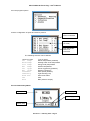
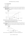
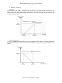
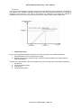
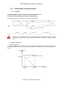
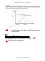
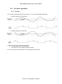
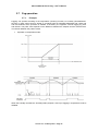
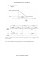
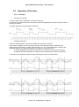
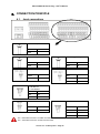
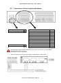
POLYCLIM 21A+Timer+Fog – User’s Manual Shade menu Operation FA01 Shade/Th.Screen Mode "Shade screen" or "thermal screen" mode Choice of operating mode for switching from "shade screen" to "thermal screen". HOUR based on programmed times LUX based on Lux sensor reading CALC. Based on Sunrise and sunset hour calculated by the regulator Min : Max : Default : HOUR CALC. CALC. FA02 Shade Start Time Start time for operation in "shade screen" mode Time from which the controller must operate in shade screen mode if the Shade/Screen mode is set to "Manual" or if there is no lux sensor connected Min : Max : Default : 0.00 FA03 8.00 FA03 Th. Screen Start Time Start time for operation in "thermal screen" mode Time from which the controller must operate in thermal screen mode if the Shade/Screen mode is set to "Manual" or if there is no lux sensor connected Min : Max : Default : FA02 23.59 20.00 FA04 Shade var. Sunrise T Variation compared to the hour of Sunrise for “shade screen” mode Variation compared to the Sunrise hour giving the hour as from which the regulator must function in “Shade screen” if the “Shade/Th.Screen Mode” is set on " Calc. " Min : Max : Défaut : -180mn +180mn 0mn FA05 Th.Scr. var. Sunset T Variation compared to the hour of Sunset for “Thermal screen” mode Variation compared to the Sunset hour giving the hour as from which the regulator must function in “Thermal screen” if the “Shade/Th.Screen Mode” is set on " Calc." (2) (2) (3) (3) Min : Max : Défaut : -180mn +180mn 0mn FA06 Morning Op. Hold Time Morning opening hold time Time during which the controller maintains the morning opening position before switching to the day time setting Min : Max : Default : 0 min 99 min 5 min FA07 Morning Opening Pulse Morning opening pulse Duration of screen opening pulses in the morning (as percentage of movement duration) Min : Max : Default : 1% 99 % 5% Min : Max : Default : 0s 99 s 5s FA08 Morning Opening Inter Interval between morning opening pulses Time between two successive opening pulses in the morning Version 3.x – February 2010 – Page 48 POLYCLIM 21A+Timer+Fog – User’s Manual FA09 Morning Control Zone Morning regulation range Percentage of opening during which the controller opens the screen in successive pulses in the morning before moving to full opening Min : Max : Default : 0% 100 % 75 % FB01 Day Opening Vent Day-time opening for sunlight Percentage of opening that the controller must leave during the day regardless of the day-time period Min : Max : Default : 0% 100 % 10 % FB02 Night Opening Vent Night-time thermal screen opening Percentage of opening that the controller must leave during nighttime Min : Max : Default : 0% 100 % 0% FB03 Morning Opening Vent Morning thermal screen opening Percentage of opening that the controller must leave in the morning during the switch from "thermal screen" to "shade screen" mode Min : Max : Default : 0% 100 % 10 % FB04 Thermal high Vent Thermal high day-time opening for temperature Percentage of opening that the controller must leave during the day when the temperature is above the thermal high setpoint Min : Max : Default : 0% 100 % 10 % FB05 Thermal low Vent Thermal low day-time opening for temperature Percentage of opening that the controller must leave during the day when the temperature is below the thermal low setpoint Min : Max : Default : 0% 100 % 0% Shade menu Opening positions Version 3.x – February 2010 – Page 49 (4) (5) POLYCLIM 21A+Timer+Fog – User’s Manual Shade menu Influencing factors FC01 Dehumid. Opening Vent Additional opening for dehumidification Percentage of opening added to the day-time opening for dehumidification Min : Max : Default : 0% 100 % 5% (6) FC02 Morn. Op. Forced Temp Temperature forcing a hold of morning opening Temperature below which the controller must hold the morning opening and disable gradual opening Min : Max : Default : -9.9 °C 99.9 °C No (= -10 °C) FC03 Morn. Op. Cancel Temp Morning opening cancellation temperature Temperature above which the controller cancels gradual opening and opens in a single stroke Min : Max : Default : -9.9 °C 99.9 °C No (= 100 °C) (1) (1) Shade menu Weather Influences (accessible only in “Expert” mode) FD01 OutT° influence start Outside Temperature influence start Value of the outside temperature from which the regulator will modify the thermal low setpoint Min : Max : Défaut : 99.9°C FD02 15.0°C FD02 OutT° influence end Outside Temperature influence end Maximum value of the outside temperature taken into account for the modification of the thermal low setpoint Min : Max : Défaut : -9.9°C FD01 5.0°C FD03 OutT° influence max Outside Temperature influence maximum Value added to the thermal low setpoint when the value of the outside temperature is equal to “OutT° influence end” Version 3.x – February 2010 – Page 50 (7) (7) (7) Min : Max : Défaut : 0.0°C 9.9°C 0.0°C POLYCLIM 21A+Timer+Fog – User’s Manual Shade menu Constructor FX01 Movement Time Screen movement time Time (in seconds) taken by the shade screen to move from fully closed to fully open Min : Max : Default : 10 s 999 s 60 s FX02 Sunniness Different. Watt differential triggering screen reopening The value which, when subtracted from the Watts threshold, provides the threshold that triggers reopening during the day Min : Max : Default : 10 W/m² 999 W/m² 50 W/m² FX03 Temperature Differ. Temperature differential triggering screen reopening The value which, when subtracted from the temperature threshold, provides the threshold that triggers reopening during the day Min : Max : Default : 0.5 °C 10.0 °C 1.0 °C FX04 Day Closing Tempo. Temporization for day closing Time during which the Watts or temperature must be greater or lower than the set thresholds before the controller closes the shade screen Min : Max : Default : 0 min 30 min 1 min FX05 Day opening Tempo. Temporization for day opening Time during which the Watts or temperature must be greater or lower than the set thresholds before the controller opens the shade screen Min : Max : Default : 0 min 30 min 4 min (4)(5) Notes : Parameter visible: (1) If the inside temperature sensor is connected (2) If FA01 is set to "Manual" (3) If FA01 is set to "Calc." and only for “expert” operation mode (4) If the inside temperature sensor is connected and AD02 is less than 100.0°C (5) If the inside temperature sensor is connected and AD03 is more than -10.0°C (6) If the "Dehumidification" option is used (7) If the outside temperature sensor is connected Version 3.x – February 2010 – Page 51 POLYCLIM 21A+Timer+Fog – User’s Manual 3.6.3. Reading screens Reading Menu shade (next : or to change screen) Screen 1/2 : 1. 2. 3. 4. 5. 6. 1. 2. 3. 4. 5. 6. Sunniness Watt Setp. Air Temp° Temp° Setp. Status Position >xxxxW/m² >xxxxW/m² > +xx.x°C > +xx.x°C > xxxxxxx > xxx% Measured sunniness (----W/m² if not detected at start-up) Sunniness setpoint Measured ambient temperature Ambient temperature setpoint Shade status : Manual, Repositioning, Immobile, Opening or Closing Calculated actual position of valve Screen 2/3 : 1. 2. 3. Influences Weather Ext.T° +xx.x°C>+x.x°C L.Therm.Setp > xx.x°C 1. 2. External temperature influence on thermal low setpoint 3. Calculated thermal low setpoint Screen 3/3 : 1. 2. 3. Influences D/N Period > D. Dehumidification > xx 1. 2. Daytime period (day/night or active period number) 3. Dehumidification in process ? ( : no / : yes) Version 3.x – February 2010 – Page 52 POLYCLIM 21A+Timer+Fog – User’s Manual 3.7. Fog operation 3.7.1. Principle Fogging can operate according to the temperature ("Cooling" function) or humidity ("Humidification" function). In both cases control is based on a setpoint with an adjustable differential and a start and end time between which operation is enabled. If necessary, the regulator controls fogging by pulse and interval. The pulse value depends on the difference between the setpoint and the measurement. The interval between the pulses is fixed. Operation in temperature mode: When the humidity exceeds the "Humidity safety setpoint", start-up of fogging in temperature mode is disabled. Version 3.x – February 2010 – Page 53 POLYCLIM 21A+Timer+Fog – User’s Manual Operation in Humidity mode: When the temperature is less than the "Temperature safety setpoint", start-up of fogging in humidity mode is disabled. In both cases, forced closure can be imposed on the air vents when fogging is operating. Version 3.x – February 2010 – Page 54 POLYCLIM 21A+Timer+Fog – User’s Manual 3.7.2. Parameters Note: - the symbol means that the menu opens after a long press In some cases parameters may be masked; see the corresponding notes at the end of the list of parameters. Setpoints Menu Fog AH01 Temperature Setpoint Fogging high temperature setpoint Air temperature above which the regulator starts up fogging (100.0°C=No) Min. Max. Default -9.9 °C 99.9 °C 30.0 °C AH02 Hygrometry Security Humidity safety point in temperature mode Air humidity above which the regulator disables start-up of fogging in temperature mode Min. Max. Default 0% 100 % No (=101%) Min. Max. Default 0% 100 % 50% Min. Max. Default -9.9 °C 99.9 °C No (=100.0°C) AH03 Hygrometry Setpoint Fogging low humidity setpoint Air humidity below which the regulator starts up fogging (101%=No) AH04 Temperature Security Temperature safety setpoint in humidity mode Air temperature below which the regulator disables start-up of fogging in humidity mode Version 3.x – February 2010 – Page 55 POLYCLIM 21A+Timer+Fog – User’s Manual Fog Menu Temp. Funct. LA01 Fog Start Time Fog operation start time in temperature mode Time from which the regulator can enable fog operation in temperature mode Min. Max. Default 00h00 23h59 00h00 LA02 Fog End Time Fog operation end time in temperature mode Time from which the regulator can no longer enable fog operation in temperature mode Min. Max. Default 00h00 23h59 23h59 LA03 Temp. Differential Fog differential in temperature mode Value which, subtracted from the fog setpoint in temperature mode, gives the fog OFF setpoint Min. Max. Default 0.5 °C 10.0 °C 1 °C LA04 Hygro. Differential Humidity safety differential Value which, subtracted from the humidity safety setpoint, gives the humidity safety OFF setpoint Min. Max. Default 2% 20 % 10 % LA05 Control Range Fog regulation range in temperature mode Zone above the fog setpoint in temperature mode in which fog pulses are proportional to the temperature Min. Max. Default 1.0 °C 50.0 °C 5.0°C LA06 Mini Pulse Duration Minimum duration of fog pulses in temperature mode Minimum fog ON time in temperature mode during the operating period Min. Max. Default 0s LA07 5s LA07 Maxi Pulse Duration Maximum duration of fog pulses in temperature mode Maximum fog ON time in temperature mode during the operating period Min. Max. Default LA06 999 s 30 s Min. Max. Default 0s 9999 s 60 s LA08 Interv. between Pulse Interval between fog pulses in temperature mode Fog OFF time in temperature mode during the operating period Version 3.x – February 2010 – Page 56 POLYCLIM 21A+Timer+Fog – User’s Manual Fog Menu Humid. Function LB01 Fog Start Time Fog start time in humidity mode Time from which the regulator can enable fog operation in humidity mode Min. Max. Default 00h00 23h59 00h00 LB02 Fog End Time Fog end time in humidity mode Time from which the regulator can no longer enable fog operation in humidity mode Min. Max. Default 00h00 23h59 23h59 LB04 Hygro. Differential Fog differential in humidity mode Value which, added to the humidity setpoint, gives the fog OFF setpoint in humidity mode Min. Max. Default 2% 20 % 10 % LB03 Temp. Differential Temperature safety setpoint differential Value which, added to the temperature safety setpoint, gives the temperature safety OFF setpoint Min. Max. Default 0.5 °C 10.0 °C 1 °C LB05 Control Range Fog regulation range in humidity mode Zone below the fog setpoint in humidity mode in which fog pulses are proportional to the humidity Min. Max. Default 5% 50% 20% Min. Max. Default 0s LB07 5s Min. Max. Default LB06 999 s 30 s Min. Max. Default 0s 9999 s 60 s LB06 Mini Pulse Duration Minimum duration of fog pulses in humidity mode Minimum fog ON time in humidity mode during the operating period LB07 Maxi Pulse Duration Maximum duration of fog pulses in humidity mode Maximum fog ON time in humidity mode during the operating period LB08 Interv. between Pulse Interval between fog pulses in humidity mode Fog OFF time in humidity mode during the operating period Version 3.x – February 2010 – Page 57 POLYCLIM 21A+Timer+Fog – User’s Manual Fog menu Influences LC01 Ventilation Influence Influence on air vents Used to force closing by a given percentage during fogging 3.7.3. Reading screens Reading Menu Fog (next : or to change screen) Screen 1/2 : 1. 2. 3. 4. 5. 6. 1. 2. 3. 4. 5. 6. Air Temp° Temp° Setp. Hygrometry Hygro Setp. Status Temporizing > +xx.x°C > +xx.x°C > xxx% > xxx% > xxxxxxx > xx:xx Measured ambient temperature Calculated running setpoint for temperature Measured ambient hygrometry Calculated running setpoint for hygrometry Fog status : Run or Stop Temporization (pulse or interval) Screen 2/2 : 1. 2. Influences Active Period > xx 1. 2. Active period number Version 3.x – February 2010 – Page 58 Min. Max. Default Yes No No POLYCLIM 21A+Timer+Fog – User’s Manual 3.8. Operation of the timer 3.8.1. Principle Operation at set times The timer output can be activated at 4 set times each day. The periods of operation after each activation can be set independently but they must all be either in seconds or minutes. The graph below shows the operation of the timer: Conditional operation It is also possible to define a sensor to condition the operation of the timer. In this mode, in addition to the 4 start-ups each day, timer operation will be conditioned by a measurement (temperature, humidity, light intensity (Lux), etc.) compared against a setpoint and adjustable positive or negative differential according to the required function: - A positive differential activates the output when the measurement is below the setpoint. - A negative differential activates the output when the measurement is above the setpoint. This mode can be disabled outside two daily operating time slots, as shown below: Version 3.x – February 2010 – Page 59 POLYCLIM 21A+Timer+Fog – User’s Manual Some examples of use: - To control an air-conditioning system according to ambient temperature: 1. Select the "Temperature" condition, 2. Set a negative differential, 3. Set the time slots (e.g. operating only during the day), 4. Set the setpoint. - To control a lighting system: 1. Select the "Lux" condition, 2. Set a positive differential, 3. Set the time slots (e.g. operating only during the night), 4. Set the setpoint, 5. If necessary, set a minimum waiting time between two start-ups. 3.8.2. Parameters Notes: - the symbol means that the menu opens after a long press, - in some cases parameters may be masked; see the corresponding notes at the end of the list of parameters. Setpoint Menu Clock AI01 Clock Setpoint Measurement setpoint for the timer Value below which (or above which) the timer will be activated when the measurement condition is used. The minimum, maximum and default values depend on the type of condition chosen: Influence Temperature Hygrometry Sunniness Luminosity CO2 Min -9.9 °C 0% 0 W/m² 0 Lux 0 ppm Max +99.9 °C 100 % 1500 W/m² 100.000 Lux 5000 ppm Default 25.0 °C 50 % 300 W/m² 2000 Lux 2000 ppm Version 3.x – February 2010 – Page 60 (1) Min.: Max. Default: POLYCLIM 21A+Timer+Fog – User’s Manual Clock Menu Operation MA01 Functioning Unit Operating unit for the timer Used to set the timer operating period after each of the 4 start-ups. MA02 P1 Starting Time Start time for Period 1 Time when the timer is activated for period 1 MA03 P1 Running Duration Operating time for Period 1 Time during which the timer operates for period 1 (in seconds or minutes depending on unit chosen) MA04 P2 Starting Time Start time for Period 2 Time when the timer is activated for period 2 MA05 P2 Running Duration Operating time for Period 2 Time during which the timer operates for period 2 (in seconds or minutes depending on unit chosen) MA06 P3 Starting Time Start time for Period 3 Time when the timer is activated for period 3 MA07 P3 Running Duration Operating time for Period 3 Time during which the timer operates for period 3 (in seconds or minutes depending on unit chosen) MA08 P4 Starting Time Start time for Period 4 Time when the timer is activated for period 4 MA09 P4 Running Duration Operating time for Period 4 Time during which the timer operates for period 4 (in seconds or minutes depending on unit chosen) Version 3.x – February 2010 – Page 61 Min.: Max. Default: SECONDS MINUTES SECONDS Min.: Max. Default: 00.00 23.59 00.00 Min.: Max. Default: 0 999 0 Min.: Max. Default: 00.00 23.59 00.00 Min.: Max. Default: 0 999 0 Min.: Max. Default: 00.00 23.59 00.00 Min.: Max. Default: 0 999 0 Min.: Max. Default: 00.00 23.59 00.00 Min.: Max. Default: 0 999 0 POLYCLIM 21A+Timer+Fog – User’s Manual Clock Menu Influence MB01 Measurement Influence Measurement used as condition None No condition Temp° Ambient temperature used as condition Hygro Ambient humidity used as condition Watt/m² Sunlight used as condition Lux Light intensity used as condition CO2 CO2 level used as condition MB02 Measurement Differ. Measurement differential for the timer Value subtracted from or added to the measurement setpoint to provide the timer stop setpoint. The minimum, maximum and default values depend on the type of condition: Condition Min. Max. Default Temperature –9.9 °C +9.9 °C 1.0 °C Humidity –20 % +20 % 10% Sunniness –999 W/m² +999 W/m² 100 W/m² Luminosity –9999 Lux +9999 Lux 500 Lux CO2 –999 ppm +999 ppm 500 ppm MB03 P1 Measur. Start Time Measurement start time for period 1 Time during period 1 when the measurement becomes active MB04 P1 Measur. End Time Measurement end time for period 1 Time during period 1 when the measurement is deactivated MB05 P2 Measur. Start Time Measurement start time for period 2 Time during period 2 when the measurement becomes active MB06 P2 Measur. End Time Measurement end time for period 2 Time during period 2 when the measurement is deactivated MB07 Minimum Interv. Tempo Minimum timer gap Minimum waiting time between two successive timer activations Notes: Parameter visible: (1) If "MB01 is other than "NONE". Version 3.x – February 2010 – Page 62 Min.: Max. Default: None Lux None (1) Min.: Max. Default: (1) Min.: Max. Default: 00.00 MB04 00.00 (1) Min.: Max. Default: MB03 24.00 12.00 Min.: Max. Default: 12.00 MB06 00.00 Min.: Max. Default: MB05 24.00 24.00 Min.: Max. Default: 00.00 03.00 00.00 (1) (1) (1) POLYCLIM 21A+Timer+Fog – User’s Manual 3.8.3. Reading screens Reading Menu Clock (next : or to change screen) Screen 1/2 : 1. 2. 3. 4. 5. 6. 1. 2. 3. 4. 5. 6. Status > xxxxxxx xx:xx (xxxxxxxxxx) P1 > xx:xx > xx:xx:xx P2 > xx:xx > xx:xx:xx P3 > xx:xx > xx:xx:xx P4 > xx:xx > xx:xx:xx Clock status : Run or Stop Actual time and functioning mode of clock Beginning and end functioning times for period 1 Beginning and end functioning times for period 2 Beginning and end functioning times for period 3 Beginning and end functioning times for period 4 Screen 2/2 : 1. 2. 3. 4. 5. 6. 1. 2. 3. 4. 5. 6. Influences Active Period > xx Measuring >xxxxxxxxx Run. Setp.>xxxxxxxxx Stop. Setp.>xxxxxxxxx Waiting Time > xx:xx Active period number Influence measurement Running setpoint for influence measurement Stop setpoint for influence measurement Temporization between two successive starts Version 3.x – February 2010 – Page 63 POLYCLIM 21A+Timer+Fog – User’s Manual 3.9. Inflation operation 3.9.1. Principle Inflation is managed by the pulse and interval principle (for example 30 seconds on and 20 minutes off) If there is a strong wind, the pulse duration is automatically increased (multiplied by the over-inflation coefficient) but the interval duration does not change. 3.9.2. Parameters Notes : - the symbol means that the menu opens after a long press - in some cases parameters may be masked; see the corresponding notes at the end of the list of parameters Inflation Menu Operation IA01 Pulse Duration Duration of inflation pulses Inflation "ON" time IA02 Interv. between Pulse Interval between inflation pulses Inflation "OFF" time Min : Max : Default : 0s 999 s 30 s Min : Max : Default : 0 min 60 min 30 min Min : Max : Default : 1.0 2.0 1.5 Inflation Menu Constructor IX01 Over-inflation Coeff. Over-inflation coefficient Value used to increase the inflation pulse duration during strong wind Version 3.x – February 2010 – Page 64 POLYCLIM 21A+Timer+Fog – User’s Manual 3.9.3. Reading screens Reading Menu Inflation 1. 2. 3. 4. Status > xxxxxxx Temporizing > xx:xx Over-inflation> xxx 1. Inflation status : Run or Stop 2. 3. Temporization (pulse or gap) 4. Over-inflation in case of strong wind ? ( : no / : yes) Version 3.x – February 2010 – Page 65 POLYCLIM 21A+Timer+Fog – User’s Manual 3.10. Alarm operation 3.10.1. Principle IMPORTANT: In some configurations, the regulator may not have an "alarm" output (see section "Power supply and output connections"). In this case, the alarms are displayed but no output is activated. If the regulator is fitted with an alarm relay, the relay contacts are closed when no alarm is detected (NC contact). The alarm relay is activated by measurements made by the regulator. Even if this function is fitted, the user must still set up an external electrical safety device (e.g. thermostat, etc.) Probes For any suitable probe connected to the analogue inputs, regulator provides: - 1 high threshold - 1 low threshold In addition a trigger delay timer (common to all the probes) prevents accidental activation of the alarm. The regulator also triggers an alarm there is a problem on a probe (disconnected or short-circuited). Network When it is configured to "Slave" mode, the regulator generates an alarm if it receives no data from the "Master" for at least 30 seconds. Inflation If the regulator includes the "Inflation" function, it is possible to set a maximum period of use in manual mode (using the R9 output switch). If the user actuates the inflation control deliberately during this period, the regulator triggers an alarm. Version 3.x – February 2010 – Page 66 POLYCLIM 21A+Timer+Fog – User’s Manual 3.10.2. Display and Acknowledgement of Alarms When an alarm occurs, the symbol emits a series of beeps. flashes at the bottom right of the screen and the regulator After this warning, use the keys to access the alarm menu via the icon . Alarm symbol The following screen appears (example): For a single-zone device Date and Time of the alarm Alarm title For a multi-zone device Zone number To select a line, use keys and . To acknowledge an alarm, use the key To return to the previous screen, use the key Before acknowledging an alarm, check that the problem is solved, otherwise the alarm will reappear. Meaning of the alarm titles: Air x Air x Air x ? High alarm on ambient temperature probe no. x Low alarm on ambient temperature probe no. x Problem on ambient temperature probe no. x (disconnected or short-circuited) Wat x Wat x Wat x ? High alarm on water temperature probe no. x Low alarm on water temperature probe no. x Problem on water temperature probe no. x (disconnected or short-circuited) Soi x Soi x Soi x ? High alarm on ground temperature probe no. x Low alarm on ground temperature probe no. x Problem on ground temperature probe no. x (disconnected or short-circuited) RH x RH x RH x ? High alarm on humidity probe no. x Low alarm on humidity probe no. x Problem on humidity probe no. x (disconnected or short-circuited) Infl. Netwo. Manual inflation alarm Network in "Slave" mode alarm Version 3.x – February 2010 – Page 67 POLYCLIM 21A+Timer+Fog – User’s Manual 3.10.3. Parameters Setpoints Menu Alarms For each connected internal sensor: AK01 Al. High xxxxxx High alarm for indicated sensor (xxxxxx) Value above which the regulator activates the alarm relay. To inhibit this alarm: set a value greater than the maximum. Min : Max : Default : AK02 sensor specific sensor specific AK02 Al. Low xxxxxx Low alarm for indicated sensor (xxxxxx) Value below which the regulator activates the alarm relay. To inhibit this alarm: set a value lower than the minimum. Min : Max : Default : sensor specific AK01 sensor specific Min : Max : Default : 0 min 999 min 10 min Min : Max : Default : 0s 999 s 30 s For the inflation function: AK09 Tpo Inflation+Manual Inflation time under manual operation Maximum operating time of inflation in manual mode before the regulator activates the alarm relay Set above 999 minutes to inhibit this alarm. Alarms Menu Operation GA01 H & L Alarms Tempo. High and low alarm temporizing Minimum time that a high or low alarm must be present before the regulator activates the alarm relay Version 3.x – February 2010 – Page 68 POLYCLIM 21A+Timer+Fog – User’s Manual 44.. CONNECTION PRINCIPLE 4.1. Input connections Exterior Temperature White A1 Blue – Interior Temperature Interior Hygrometry White A2 White + Blue – Blue A6 Wind Vane 0-360° Wind Vane both sides White + Blue + Blue A5 Red T3 White T4 Luminosity / Sunniness 0-100.000 Lux 0-1.500 Watt/m² Blue + Red A7 White A8 Anemometer Rain Stand-alone White + White + Blue T1 Blue T2 Red CH1 Yellow CH2 The + terminals are for the 15 VDC from the PCB The – terminals are for the 0 VDC from the PCB Version 3.x – February 2010 – Page 69 POLYCLIM 21A+Timer+Fog – User’s Manual 4.2. Connection of power supply and outputs 230VAC power supply live 230VAC power supply neutral L N 24VAC Output (25VA max.) 24VAC Output (25VA max.) O P Opening Ventilation 1 Closing Ventilation 1 Opening Ventilation 2 Closing Ventilation 2 Opening Shade Closing Shade Fog Timer Inflation Thermostatic Heating Air Mixer Alarm (N.C. contact) Output Common R1 R2 R3 R4 R5 R6 R7 R8 R9 R10 R11 R12 K The PCB power supply must be protected by a Gg 1A fuse or a Curve C 1A circuit breaker. The outputs are « 24 V, 1 A max ». Terminal K is common to all outputs Direct connections to motor units type C1MA, C1MA/SA/AUTO, C1MG, C1MC, … Version 3.x – February 2010 – Page 70 POLYCLIM 21A+Timer+Fog – User’s Manual 55.. CHARACTERISTICS AND PRECAUTIONS 5.1. General characteristics SUPPLY VOLTAGE: VOLTAGE TOLERANCE: CONSUMED POWER: OUTLETS: WEIGHT: DIMENSIONS: PROTECTION: STORAGE TEMPERATURE: TEMPERATURE OF USE: AIR HUMIDITY: 5.2. WARNING 230VAC single-phase 50/60 Hz +/–10% 50VA maxi Dry contacts maximum 5A/24V Approx. 2 kg L = 220 mm / H = 260 mm / D = 80 mm IP445 –10°C to +60°C 0°C to 50°C Maximum 93% without condensation installation safety Climate regulation devices installed in a greenhouse do not contain independent alarm devices. In the event of malfunction caused by the general installation (mechanical or electrical components, cables, probes, weather sensors, regulation system electronics, operating error, etc.), a climate regulator or computer cannot be considered to be a safety device capable of rendering the installation safe or alerting the greenhouse user. To guarantee the safety of greenhouse, you must install an independent, standalone alarm unit with its own detectors (such as VIGICLIM or equivalent) capable of triggering real-time alarms and providing event traceability. The manufacturer draws greenhouse owners' and/or users' attention particularly to the fact that regulation systems operate in "open loop" configuration and therefore do not monitor the real position of vents but only a calculated theoretical position. In addition, special care must be given to preventive maintenance of equipment, especially weather probes and sensors. Periodic inspections and tests are essential for checking the reliability of alarm unit equipment and sensors. The manufacturer is only liable for damage resulting from an operating fault on its equipment being used for its designed climate regulation function and provided that installation, operation and servicing standards are observed. 5.3. Precautions for use Avoid direct sun exposure. Avoid water spraying. Avoid shocks. Avoid excessive pressure on keys. Do not open the device; in this instance, the warranty does not apply. Do not connect or disconnect a sensor or an outlet without shutting off power. Do not connect a sensor other than those specified in documentation. These devices must be installed by authorized technicians. Follow the precautions for installation and use; otherwise, warranty shall not apply. Version 3.x – February 2010 – Page 71 POLYCLIM 21A+Timer+Fog – User’s Manual 5.4. Precautions for installation Important instructions for the installation of devices with microprocessor. Changes in the supply system are only allowable within the specified tolerances (install a voltage regulator or an inverter, if required). Protection of the device against lightning surges (surge diverters) and against phase inversions (checking relay) is recommended In the event of interference systems (e.g., thyristor controls), it is recommend that the device be supplied through a separate transformer. Do not install the devices under high-voltage power lines. Do not position sensor or signal cables near control and power cables (required minimum distance: 50 cm). Use shielded measuring lines as much as possible and ground them at one end on the side of the controller. Install power circuits at a sufficient distance from electronic devices. If inductive circuits, such as contactors, solenoid valves, etc., are installed near the device, it is essential to suppress their coil with RC filters. Do not connect control circuits (relays, contactors) on the quick-connect terminals to the supply circuit of the device. The supply of the devices using a generating unit requires special precautions, in particular: o Make the connection to the generating unit when the unit is in steady-state condition. o Set the generating unit to ensure a 230V supply of the devices within the specified tolerances (230VAC ± 10%, 50 or 60Hz). Use an appropriate screwdriver to connect the wires to the device terminal board. Maximum 2 sectional area of wires: 1.5 mm , maximum 2 wires per terminal. Make sure to wire the star-shaped ground conductor. Important instructions for the installation and maintenance of sensors. Do not position sensor or signal cables near control and power cables (required minimum distance: 50 cm). Maximum length of sensor cables: o temperature and hygrometry sensors: 100 meters o Weather sensors: 10 meters Version 3.x – February 2010 – Page 72 POLYCLIM 21A+Timer+Fog – User’s Manual If extension cords are necessary, use shielded twisted pair cable (the shield should be linked to one end to the ground of the controller) The junction boxes used for the sensor extension cords, should be waterproof. Connect weather sensors and probes to a dead controller. The "Weather" sensors should be: o installed on 1 mast at 1 meter above the greenhouse structure on the side of the “prevailing wind”, o protected against turbulence and dust, o away from disturbing sources (high mast lighting structure, high-voltage power lines, etc.), o checked and cleaned on a regular basis (without scratching sensor surface). The ambient temperature sensor is usually hung in the middle of the greenhouse (avoid areas with air drafts). The hygrometry sensor, which is also installed in the middle of the greenhouse, should be protected as much as possible against treatment products. Clean and recondition the sensor on a regular basis. Version 3.x – February 2010 – Page 73 POLYCLIM 21A+Timer+Fog – User’s Manual If the Watt/m² or Lux sensors are installed inside the greenhouse, avoid cast shadows related to the greenhouse structure. Check and clean the filter of ventilated sensors weekly. Direct the weathervane properly. Install the pluviometry, temperature and external hygrometry sensors on a stand, in a site that was cleared on a 10 m ray, avoiding ventilated areas. The stand must be well secured in the ground (mass concrete or equivalent). Version 3.x – February 2010 – Page 74 POLYCLIM 21A+Timer+Fog – User’s Manual SUMMARY 11.. 1.1. 1.2. 1.3. GENERAL PRESENTATION ...................................................................................................... 2 Functions ................................................................................................................................. 2 General diagram ...................................................................................................................... 2 Options .................................................................................... Error! Bookmark not defined. 22.. USE OF THE DEVICE ................................................................................................................ 3 2.1. Browsing .................................................................................................................................. 3 2.2. Integrated manual operation.................................................................................................. 10 2.3. Network connection ................................................................. Error! Bookmark not defined. 2.4. General Parameters .............................................................................................................. 12 2.4.1. Date and Time ............................................................................................................... 12 2.4.2. Sensor Calibration and Maintenance Mode .................................................................. 12 2.4.3. System ........................................................................................................................... 13 33.. FUNCTIONS .............................................................................................................................. 16 3.1. Weather detection ................................................................................................................. 16 3.1.1. Principle ......................................................................................................................... 16 3.1.2. Parameters .................................................................................................................... 18 3.1.3. Reading screens ............................................................................................................ 20 3.2. Vent operation ....................................................................................................................... 21 3.2.1. Principle ......................................................................................................................... 21 3.2.2. Parameters .................................................................................................................... 25 3.2.3. Reading screens ............................................................................................................ 32 3.3. Thermostatic heating operation ............................................................................................. 34 3.3.1. Principle ......................................................................................................................... 34 3.3.2. Parameters .................................................................................................................... 35 3.3.3. Reading screens ............................................................................................................ 37 3.4. Air mixer operation ................................................................................................................ 39 3.4.1. Principle ......................................................................................................................... 39 3.4.2. Parameters .................................................................................................................... 40 3.4.3. Reading screens ............................................................................................................ 41 3.5. Dehumidification operation .................................................................................................... 42 3.5.1. Principle ......................................................................................................................... 42 3.5.2. Parameters .................................................................................................................... 43 3.5.3. Reading screens ............................................................................................................ 45 3.6. Shade curtain operation ........................................................................................................ 46 3.6.1. Principle ......................................................................................................................... 46 3.6.2. Parameters .................................................................................................................... 47 3.6.3. Reading screens ............................................................................................................ 52 3.7. Fog operation......................................................................................................................... 53 3.7.1. Principle ......................................................................................................................... 53 3.7.2. Parameters .................................................................................................................... 55 3.7.3. Reading screens ............................................................................................................ 58 3.8. Operation of the timer ............................................................................................................ 59 3.8.1. Principle ......................................................................................................................... 59 3.8.2. Parameters .................................................................................................................... 60 3.8.3. Reading screens ............................................................................................................ 63 3.9. Inflation operation .................................................................................................................. 64 3.9.1. Principle ......................................................................................................................... 64 3.9.2. Parameters .................................................................................................................... 64 3.9.3. Reading screens ............................................................................................................ 65 3.10. Alarm operation ..................................................................................................................... 66 3.10.1. Principle ......................................................................................................................... 66 3.10.2. Display and Acknowledgement of Alarms ..................................................................... 67 3.10.3. Parameters .................................................................................................................... 68 Version 3.x – February 2010 – Page 75 POLYCLIM 21A+Timer+Fog – User’s Manual 44.. 4.1. 4.2. CONNECTION PRINCIPLE ...................................................................................................... 69 Input connections .................................................................................................................. 69 Connection of power supply and outputs .............................................................................. 70 5.1. CHARACTERISTICS AND PRECAUTIONS ............................................................................. 71 General characteristics .......................................................................................................... 71 5.2. 5.3. 5.4. WARNING installation safety ....................................................................................... 71 Precautions for use ................................................................................................................ 71 Precautions for installation .................................................................................................... 72 55.. Version 3.x – February 2010 – Page 76