1
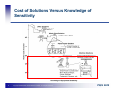
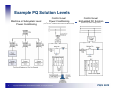
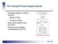
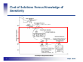
Voltage Sag Mitigation Methods
10/28/09 1:15 pm – 2:00 pm
Mark Stephens, PE
Senior Project Manager
Industrial Studies
Electric Power Research Institute
942 Corridor Park Blvd
Knoxville, Tennessee 37932
Phone 865.218.8022
[email protected]
1
Cost of Solutions Versus Knowledge of
Sensitivity
2
Copyright © 2009 Electric Power Research Institute, Inc. All rights reserved.
PQIG 2009
Example PQ Solution Levels
Machine or Subsystem Level
Power Conditioning
3
Control Level
Power Conditioning
Control Level
Embedded DC Solution
(1/10th to 1/20th of Machine Level Power Conditioner Cost)
(Best done by OEM in design phase)
Copyright © 2009 Electric Power Research Institute, Inc. All rights reserved.
PQIG 2009
Designing
in Embedded
Solutions
4
Method 1: Design with DC Power
• One of the best methods of
increasing the tolerance of control
circuits is to use direct current (DC)
instead of alternating current (AC) to
power control circuits, controllers,
input/output devices (I/O), and
sensors.
• DC power supplies have a “built-in”
tolerance to voltage sags due to their
ripple-correction capacitors, whereas
control power transformers (CPTs)
and AC components do not have
inherent energy storage to help them
ride through voltage sags
• Many OEMs are moving in this
direction to harden their equipment
designs
5
Copyright © 2009 Electric Power Research Institute, Inc. All rights reserved.
DC Powered Emergency Off Circuit
PQIG 2009
PLC Using DC Power Supply Scheme
• How Much Better is the DC
solution?
– Depth of Sag
– Duration of Sag
• What other benefits does
DC have?
• What are some design
considerations with DC?
DC Powered PLC Circuit
6
Copyright © 2009 Electric Power Research Institute, Inc. All rights reserved.
PQIG 2009
DC Powered PLC System in Weld Shop
7
Copyright © 2009 Electric Power Research Institute, Inc. All rights reserved.
PQIG 2009
Summary of Robust Power Supply Strategies: Relative
Power Supply Response at 100% Loading
Ride-Through for
Single-Phase Voltage
Sags
8
Copyright © 2009 Electric Power Research Institute, Inc. All rights reserved.
PQIG 2009
Method No. 2: Utilize Sag Tolerant
Components
•
•
•
IF AC Relays and Contactors are
used in the semiconductor tool
design, then utilize compliant
devices.
Consider response at both 50
and 60 Hz.
We have certified a many relays
and contactors to SEMI F47.
Telemecanique LC1F150 Coil LX9FF220
Voltage Sag Ride Through Curve
Voltage (% of Nominal)
DUT 60HZ
SEMI F47
DUT 50HZ
100%
80%
60%
40%
20%
0%
0
0.1
0.2
0.3
0.4
0.5
0.6
0.7
0.8
0.9
1
Duration (in seconds)
9
Copyright © 2009 Electric Power Research Institute, Inc. All rights reserved.
PQIG 2009
Example Voltage Sag Response of Motor
Controls Based on Robustness of
Components
10
Copyright © 2009 Electric Power Research Institute, Inc. All rights reserved.
PQIG 2009
Method 3: Apply Custom Programming
Techniques – Delay Filters
•
•
•
11
Delay filters can be verify the
presence of power and work as
a “de-bounce” mechanism for
when components drop out due
to a voltage sag. The PLC
motor-control circuit shown
demonstrates how this method
can be applied.
The program is designed to
detect whether the auxiliary
contact is open for more than
250 milliseconds.
If the contact is open for more
than that preset time, then the
“Timer On Delay Coil” in Rung 2
will be set and unlatch the
previous rung to remove voltage
from the motor starter.
Copyright © 2009 Electric Power Research Institute, Inc. All rights reserved.
PQIG 2009
Method 3: Apply Custom Programming
Techniques –State Machine Programming
•
•
•
12
State Machine Programming is
based on the idea that
manufacturing processes are
comprised of a number of steps
with the goal of producing and
moving a product.
Therefore, machine-state
programming keeps track of
every sequential process state
and associated variables by
writing variables to non-volatile
memory in the event power is
lost.
When power returns, the
processing step number and
variables can be recalled so that
the machine can continue from
where it stopped.
Copyright © 2009 Electric Power Research Institute, Inc. All rights reserved.
PQIG 2009
Method 3: Apply Custom Programming
Techniques – Programming Using
Phase/Voltage Sensing Relay
• A phase monitor or voltage
sensing relay, used in conjunction
with programming, can also
protect against the effects of
voltage says.
• The relay contacts can be used to
run a check on the system, retrieve
past information stored in
memory, or hold control
parameters constant until the
event is over.
13
Copyright © 2009 Electric Power Research Institute, Inc. All rights reserved.
Potential Sensing Devices For Voltage Sags
(Left to Right)
Phase Monitoring Relay
PQ Relay
“Original” PQ Relay (AC Ice Cube)
PQIG 2009
Method 4 – Examine Configuration Settings
• A low-cost or perhaps no-cost
method of increasing the
tolerance of AC and DC motor
drives to voltage sags is through
software configuration settings.
• This method applies to all types
of drives, including, but not
limited to, AC pulse-width
modulation (PWM), directcurrent, AC-pulse, stepper, and
servo drives.
14
Copyright © 2009 Electric Power Research Institute, Inc. All rights reserved.
PQIG 2009
Method 4 – Examine Configuration Settings
Functional Description:
Automatic Reset and Automatic Restart
• In most cases, drive
manufacturers give users
access to basic microprocessor
program parameters so that the
drive can be configured to work
in the user’s particular
application.
• A drive’s programming
parameters associated with
reducing the effect of voltage
sags are seldom describes in
one section of the user manual.
15
Copyright © 2009 Electric Power Research Institute, Inc. All rights reserved.
PQIG 2009
Method 4 – Examine Configuration Settings
Functional Description: Motor Load Control
Motor-load control uses the motor’s inertia or controlled
acceleration/deceleration to ride-through voltage sags.
16
Copyright © 2009 Electric Power Research Institute, Inc. All rights reserved.
PQIG 2009
Method 4 – Examine Configuration Settings
Functional Description: Phase Loss and DC Link Undervoltage
Detecting a loss of phase enables a drive to delay a fault condition
and ride through the loss of phase. The DC link undervoltage trip
point can be adjusted to enable a drive to ride through sags.
17
Copyright © 2009 Electric Power Research Institute, Inc. All rights reserved.
PQIG 2009
Example Settings Rockwell Power Flex 70 &
700
• Conducted SEMI F47
compliance Testing on Power
Flex 70 and 700 Series drives in
EPRI Lab.
• Drives have built in parameters
that can be used to improve
voltage sag performance.
• Drives loaded to 100%
18
Copyright © 2009 Electric Power Research Institute, Inc. All rights reserved.
PQIG 2009
Typical Drive Test Setup
Dynamometer Control
System
Test Setup for Larger Drives
(20 to 150HP)
Voltage Sag
Generator
Nicolet
Data Recorder
Drive Under
Test
Dynamic
Dyno AC
Motor
Motor Load
Drive Under
Test
Test Setup for Smaller Drives
Eddy
Current
Brake
Motor Load
(2 to 15 HP)
Nicolet
Data Recorder
Voltage Sag
Generator
19
Copyright © 2009 Electric Power Research Institute, Inc. All rights reserved.
PQIG 2009
Example
Response
• Example Worst
Case Speed
Deviation: 12
Cycles, 50% Vab
without Line
Reactor
• Set for P184=
“DECEL” mode
20
Copyright © 2009 Electric Power Research Institute, Inc. All rights reserved.
PQIG 2009
Example
Response
• Example Worst
Case Speed
Deviation: 12
Cycles, 50% Vab
without Line
Reactor
• Set for P184=
“Continue” mode
21
Copyright © 2009 Electric Power Research Institute, Inc. All rights reserved.
PQIG 2009
Schneider-Toshiba Altivar 61 & 71 Drives
• This newer drive series was
recently tested as a part of the
EPRI PQ Star SEMI F47
compliance program.
• Drives were found to pass the
standard.
• Certification Relates to multiple
drive models manufactured from
same control platform
– STI Altivar 61 and 71
– ELIN >pDRIVE<
– MX ECO and MX PRO
Altivar 61 and 71 Series Drives
22
Copyright © 2009 Electric Power Research Institute, Inc. All rights reserved.
PQIG 2009
Schneider-Toshiba Altivar 61 & 71 Drives
• The drives were able to pass the
SEMI F47 testing requirements
when configured properly.
• Prameters such as "Input
Phase Loss", "Catch on the Fly",
and Undervoltage Timeout (UV
Timeout) had to be set.
• The dynamic torque profile was
test to follow the "High Torque
A" and the default slip
compensation was set to 100%.
23
Copyright © 2009 Electric Power Research Institute, Inc. All rights reserved.
Parameter
Setting
Input Phase Loss
Ignore
Catch on Fly
Yes
UV Timeout
3 sec
UV Prevention
DC maintain
Slip Compensation
100% (default)
Dynamic Torque
High Torque A
PQIG 2009
Method 5 – Select Appropriate Trip Curves
for Circuit Breakers
24
Copyright © 2009 Electric Power Research Institute, Inc. All rights reserved.
PQIG 2009
Other Considerations
• Make sure the device rated voltage matches the nominal
voltage. Mismatches can lead to higher voltage sag
sensitivities (for example 208Vac fed to 230Vac rated
component).
• Consider Subsystem performance. Vendor subsystems must
be robust for the entire system to be robust. Otherwise, power
conditioning may be required for the subsystem.
• Consolidate Control Power Sources. This will make the
implementation of any required power conditioner scheme
much simpler and cost effective.
• Use a targeted voltage conditioning approach as the last
resort. Apply Batteryless power conditioner devices where
possible (next).
25
Copyright © 2009 Electric Power Research Institute, Inc. All rights reserved.
PQIG 2009
Use of Selective
Power Conditioners
26
“Selective” Conditioning
The Premise:
All equipment power users are not ultra-sensitive.
The Plan:
To prop up the single-phase “weak links” only.
The Weak Links:
Small, single-phase 100Vac-230Vac, typically power
supplies, sensors and controls.
The Benefit: Lower Cost than Macro Solutions.
27
Copyright © 2009 Electric Power Research Institute, Inc. All rights reserved.
PQIG 2009
Uninterruptible Power Supply (UPS)
For Control Loads
Small 500Va to
3kVA
UPS Systems are
sometimes Used
Battery Based
UPS
Are Often
“Overkill”
“Abandoned in Place” UPS Systems
28
Copyright © 2009 Electric Power Research Institute, Inc. All rights reserved.
PQIG 2009
Square Wave Compatibility
with PLCs
DPI
PLC Model
Compatible
with 120Vac
Input Cards?
Outcome with
APC Smart UPS 420
Outcome with
APC Back UPS Pro 650
Omron (PLC A)
No
Toggling input could not
be resolved
Toggling input could not
be resolved
TI 545 (PLC B)
No
All inputs dropped
leading to the logical
decision to drop the
control relay
All inputs dropped
leading to the logical
decision to drop the
control relay
Quantum (PLC C)
No
Same as TI 545
Same as TI 545
AB PLC-5 (PLC D)
Yes
No Effect, System OK
AB SLC 5/03 (PLC E)
29
Square Wave Output UPS
Yes
Copyright © 2009 Electric Power Research Institute, Inc. All rights reserved.
No Effect, System OK
No Effect, System OK
No Effect, System OK
PQIG 2009
UPS Coverage vs.
Sample Historical Data
30
Copyright © 2009 Electric Power Research Institute, Inc. All rights reserved.
PQIG 2009
MiniDYSC
• The Dynamic Sag
Corrector from
Softswitching
Technologies
• Deep Sag Coverage
especially when lightly
Loaded
• Has Capacitors that allow
for some ride-through for
interruptions
• Would handle all sags
seen by equipment
during monitoring period.
– http://www.softswitch.
com
31
Copyright © 2009 Electric Power Research Institute, Inc. All rights reserved.
PQIG 2009
Voltage Dip Compensator (VDC)
• No batteries; no maintenance.
• Fast compensation.
• Able to withstand high inrush
currents.
• Small footprint, easy to retrofit.
• Support exceeds SEMI F47
standard requirements.
• 120Vac and 208Vac Models
• www.measurelogic.com
• www.dipproof.com
32
Copyright © 2009 Electric Power Research Institute, Inc. All rights reserved.
PQIG 2009
Dip Proof Inverters (DPI)
• No batteries; therefore, no replacement
and maintenance costs or hazardous
waste.
• Fast (<700µS) transfer, off-line system
develops little heat & fails to safety.
• Able to withstand high inrush currents;
no need to oversize as with UPS’s &
CVT’s.
• Lightweight, small & easy to retrofit; no
step-up transformers or batteries.
• Accurate application control; adjustable
ride through time & variable transfer
level.
• Primarily designed for inductive and low
power factor loads.
• 120Vac and 208Vac Models
• Square Wave Output
• www.measurelogic.com
• www.dipproof.com
33
Copyright © 2009 Electric Power Research Institute, Inc. All rights reserved.
PQIG 2009
PowerRide RTD
• Uses two phases of a threephase supply as input and a
single-phase output.
• If one phase in interrupted,
constant power out of the
RTD....Even if the remaining
phase drops by a third.
• Typically No Need to oversize
for Inrush
– http://www.uppi-ups.com
34
Copyright © 2009 Electric Power Research Institute, Inc. All rights reserved.
PQIG 2009
Constant Voltage Transformer (CVT)
• On-line Device. In-Rush Current
of load(s) MUST be considered
in sizing.
• Output of CVT can collapse
when in-rush current gets close
too high ( around 4 x rated size).
• Sub-Cycle Response.
• Should be oversized to at least
2 times nominal of load to
increase ride-through.
• Acts as an isolation transformer
and protects against voltage
sags.
35
Copyright © 2009 Electric Power Research Institute, Inc. All rights reserved.
PQIG 2009
Example CVT Application
• The CVT is protecting only the
AC control components means
that the selected power
conditioner will be more
affordable than one that could
protect the entire machine.
• The ride-though of the AC
drives in this example can be
enhanced by modifying their
programming, thus eliminating
the need for a large power
conditioner.
36
Copyright © 2009 Electric Power Research Institute, Inc. All rights reserved.
PQIG 2009
Coil Hold In Devices
• Will prop up relay or contactor coil
down to 25% of nominal voltage
sag.
• Customer will need to final Size the
coil hold-in device based on
Voltage and Coil Resistance
(measure with an ohm meter)
• Cost: less than $150-250 USD per
unit
• Suppliers
• www.pqsi.com (UL Certified)
• www.scrcontrols.com
37
Copyright © 2009 Electric Power Research Institute, Inc. All rights reserved.
Example Device
PQIG 2009
Machine and
Panel Level
Solutions
38
Cost of Solutions Versus Knowledge of
Sensitivity
39
Copyright © 2009 Electric Power Research Institute, Inc. All rights reserved.
PQIG 2009
Pro-DySC
• The ProDySC provides
equipment and process level
protection without the use of
batteries or fly wheels.
• The unit can boost incoming line
voltage and provide momentary
ride through protection for sags
down to zero volts.
• It is designed to handle shortterm sags up to two seconds
with a 30 second recharge time.
• This unit is three phase, 200480 volts, 25-200 amps, and
supports between 333 and
2000kVA.
40
Copyright © 2009 Electric Power Research Institute, Inc. All rights reserved.
PQIG 2009
Omniverter AVC
• The Active Voltage Conditioner
(AVC) consists of an inverter which
feed an injection transformer in
series with the utility.
• The inverter allows the unit to
correct utility disturbances.
• Since there are no storage devices
no maintenance is required. It
comes in a three-phase 208, 480,
and 600 volts but has 400 and 690
volt options.
• It has a very fast response time of in
less than a millisecond because it is
continuously running.
• It can also protect against rapidconsecutive sags
41
Copyright © 2009 Electric Power Research Institute, Inc. All rights reserved.
PQIG 2009
Purchase Bypass with unit
42
Copyright © 2009 Electric Power Research Institute, Inc. All rights reserved.
PQIG 2009
Example Control Level Solutions at the
Distribution Panel and Recommendations
• Sometimes the most effective
solution is to provide
conditioned power for the entire
IPP Panel. Advantages of this
approach include:
– Simplified Cut Over/Fewer
Touch Points
– Single Power Conditioner for
many loads
– When sized to support kVA
of transformer, this approach
will support future expansion
in panels
43
Copyright © 2009 Electric Power Research Institute, Inc. All rights reserved.
PQIG 2009