1
BUS/KNX modular controller
for dimming - DALI protocol
Catalogue number(s): 0 0
26 35
5. MENU OPERATION AND STRUCTURE (continued)
6. COMMISSIONING (continued)
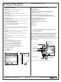
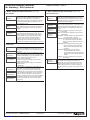
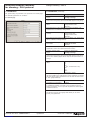
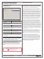
FUNCTION INPUT B2
6.1 Commissioning DALI using buttons and the
device screen (continued)
If push-buttons are connected to the device inputs, use the
FUNCTION INPUT B1 and B2 menus to define the push-button
function and assign the inputs to the various DALI groups. This allows
the DALI functions to be executed (operations performed on site) even
before the KNX is up and running. In addition, the binary inputs can
also be used in normal operating mode to integrate standard light-duty
push-buttons or presence sensors in the system.
FUNCTION
INPUT B2
TOG/DIM
INPUT B2
TOG/DIM
GROUP: ALL
SCENE: 2
—>invoke
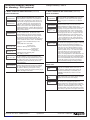
The Prg/Set button can be pressed briefly to
go from the FUNCTION INPUT B2 main menu
to the submenu. This submenu can be used to
define the function of the volt-free push-button
connected to binary input B2.
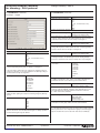
To go from one available function to another,
press the Move button briefly. The number of the
currently selected function appears on the first
line of the display. The following functions can
be set:
• ON: The function is enabled by pressing the
push-button.
• OFF: The function is disabled by pressing the
push-button.
• TOGGLE: Switches between On and Off when
the push-button is pressed.
• ON/DIM: Push-button pressed briefly: lights
up; push-button pressed and held
down: increasing dimming with stop
telegram.
• OFF/DIM: Push-button pressed briefly: goes
off; push-button pressed and held
down: gradual decrease with stop
telegram.
• TOG/DIM: Push-button pressed briefly:
switches between On and Off;
push‑button pressed and held down:
dimming by simply holding down the
button.
• SCENE: A scene is invoked by pressing the
push-button.
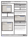
Pressing and holding down the Prg/Set button
sets the device to programming mode. To
choose the scene or the channel to which the
selected function will be connected, press the
Move button briefly. Press the ESC button (or
wait 30 seconds) to go back to the higher menu
level.
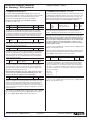
Finally, groups can be assigned to the various scenes using the
SCENE ASSIGNMENT menu (see menu operation and structure
above).
Commissioning the DALI segment is then complete.
Commissioning the KNX parameter setting can be started immediately
or later using the ETS software and the corresponding application
program.
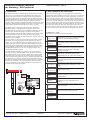
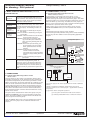
x 64
KNX
power
supply
035 12
KNX/DALI
controller
**
ETS software
035 43
**
026 35
OR
035 47
b USB
**
ETS software
SCS OFFER
Control units and detectors in
the SCS offer
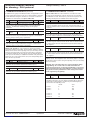
6. COMMISSIONING
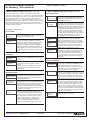
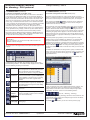
Assign the devices detected to the various DALI groups using the
GROUP ASSIGNMENT menu (see menu operation and structure
above). The basic installation is complete when all the ECGs have
been assigned to the desired groups.
a RJ 45
Manual
SCS*
power
supply
6.1 C
ommissioning DALI using buttons and the
device screen
Once the device has been wired up in accordance with the above
instructions, the DALI line can be commissioned. This operation can
be performed independently of commissioning the KNX bus. While
KNX is not connected, the red error LED lights up to indicate an error.
DALI can still be commissioned, however. For the initial installation,
start by finding the DALI line for all the connected ECGs using the
NEW INSTALLATION menu (see menu structure described above).
Once all the connected devices have been detected (indicated by
(ESC) behind the number of devices detected indicated on screen),
quit this menu element.
Configuration option **
KNX OFFER
035 67
KNX/SCS
interface
026 34
*SCS power supply Cat. No. 035 67 supplied with Cat. No. 026 34 (KNX/SCS
interface)
**Option of configuring the KNX/DALI controller directly via the RJ 45
connection (requires use of a software program... supplied with the commonly
used product)
a b: product software configuration possible via
a: IP using the IP communication module Cat. No. 0 035 43
b: USB using the BUS/KNX interface - USB Cat. No. 0 035 47
Using the GROUP TEST menu (see menu operation and structure
above), each of the groups can be enabled or disabled for test
purposes.
Technical data sheet: S000064593EN-1
CONTENTS
Updated on:
Created on: 15/06/2012
7/14