1
BUS/KNX modular controller
for dimming - DALI protocol
Catalogue number(s): 0 0
26 35
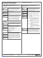
2. TECHNICAL FEATURES
2. TECHNICAL FEATURES (continued)
Power supply
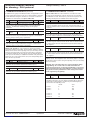
• Power supply 110 to 240 V, 50 to 60 Hz, 0.1 A max.
• Additional power supply via the KNX bus
Electrical safety
• Degree of pollution: 2
• Protection (in accordance with standard EN 60529): IP20
• Protection class: (in accordance with standard IEC 1140) I
• Overvoltage class: III
• Bus: Safety extra low voltage (SELV) 24 V DC
Control elements
• Programming button for toggling between normal mode and
addressing mode
• 3 buttons (MOVE, Prg/Set, ESC) on the front can be used to set the
device and the parameters
Conformity to electromagnetic compatibility standards
Conforms to standards EN 50081-1, EN 50082-2 and EN50090-2-2
Display elements
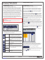
• Red LED indicating whether the device is operating in normal mode
or in addressing mode
• Green PWR LED indicating that the device is ready to operate
(flashes in normal operating mode)
• Red ERR LED indicating error status.
• 2 x 12-character display for navigating through the menus for
commissioning and parameter setting
Environmental specifications
• Resistance to the weather: EN 50090-2-2
• Operating temperature: 0°C to +45°C
• Storage temperature: -25°C to +70°C
• Relative humidity (non-condensing): 5 to 93%
Inputs
• Volt-free binary input, passive for connecting push-buttons or the
9-32 V DC or 8-26 V AC presence sensor, max. wire length: 15 m
CE certified
DALI bus
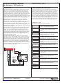
• Connection of 64 ECGs maximum, in accordance with standard
IEC 60926
• DALI 18-21 V DC voltage, short-circuit protection
• No other control device (master DALI devices) should be used
Ethernet
• IP connection via Ethernet, rate 10 Mbps, only used for
commissioning DALI
• IP address assignment by a DHCP service or fixed IP address
Connectors
• Bus line: KNX bus coupler
• Power supply: 3 x 1.5 mm² screw-type connector
with single-core cable or threaded conductor
• DALI bus: 3 x 1.5 mm² screw-type connector
with single-core cable or threaded conductor
• Binary input: 3 x 1.5 mm² screw-type connector
with single-core cable or threaded conductor
• Ethernet: RJ 45 socket for standard connection cable
Certification
KNX approved
3. L
OCATION AND FUNCTION OF THE CONTROL AND
DISPLAY ELEMENTS
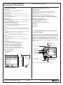
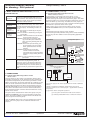
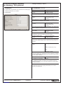
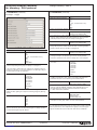
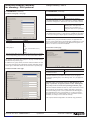
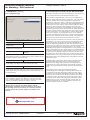
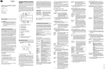
The device connectors and the LED and programming button, which
are necessary elements for commissioning, are only accessible once
the switchboard cover has been lifted out of the way. However, the
programming buttons (MOVE, Prg/Set, ESC), which are necessary
elements for commissioning the DALI interface and setting the
parameters, can be enabled with the cover closed. The two-line menu
display and the control LEDs (PWR and ERR) can also be read with
the cover closed.
Connector passive
binary input 1
Connector passive
binary input 2
DALI connector
Operating LED
Mechanical characteristics
• Case: Plastic PA66 – V0
• Case dimensions:
• Weight : 200 g
MOVE button
Prg/Set button
ESC button
2 x 12-character display
for configuring the DALI
interface
86
106
Programming button
Programming LED
55
RJ 45 socket
for the Ethernet connection
Error LED
Always comply with the connector labelling on the case.
• Mounting: On 35 mm DIN rail
Technical data sheet: S000064593EN-1
CONTENTS
Updated on:
Created on: 15/06/2012
2/14