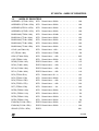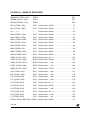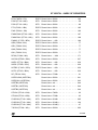
1
ST10R272L - GENERAL PURPOSE TIMER UNITS
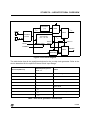
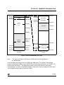
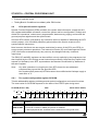
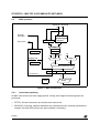
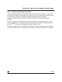
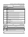
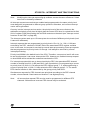
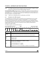
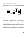
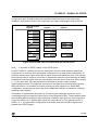
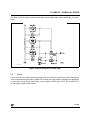
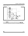
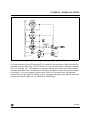
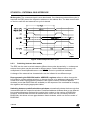
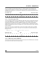
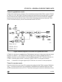
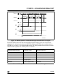
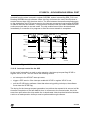
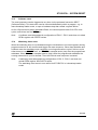
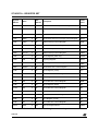
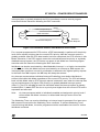
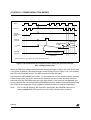
each transition on one or both of the external input pins which gives 2-fold or 4-fold
resolution to the encoder input.
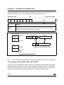
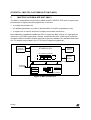
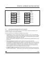
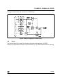
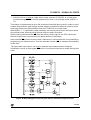
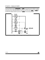
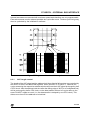
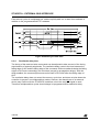
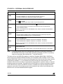
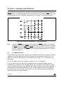
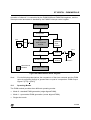
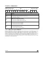
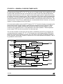
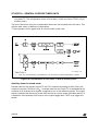
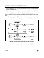
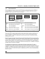
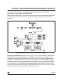
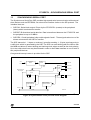
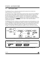
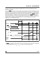
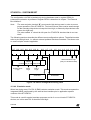
T3R
T3IN
edge detect
T3
Up/Down
T3IR
T3OUT
T3OTL
T3OE
T3EUD
phase detect
XOR
MUX
T3UD
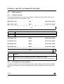
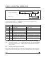
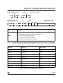
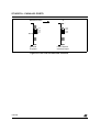
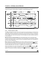
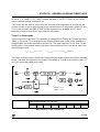
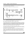
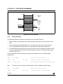
Figure 73 Core timer T3 in incremental interface mode
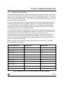
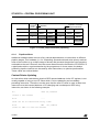
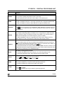
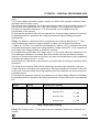
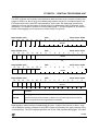
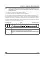
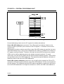
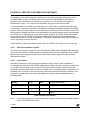
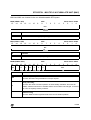
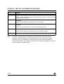
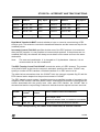
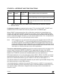
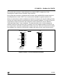
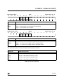
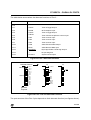
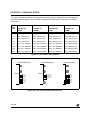
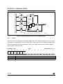
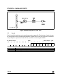
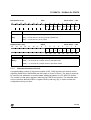
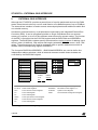
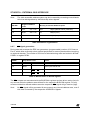
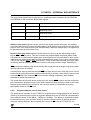
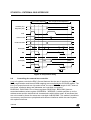
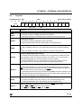
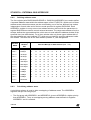
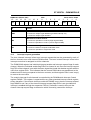
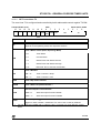
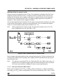
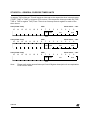
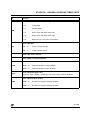
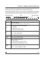
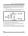
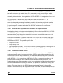
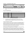
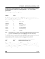
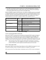
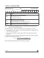
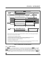
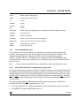
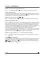
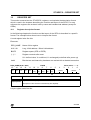
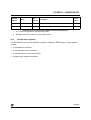
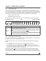
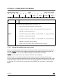
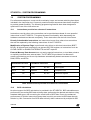
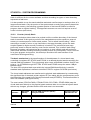
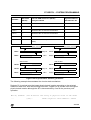
Bitfield T3I in the T3CON control register selects the triggering transitions (see table below).
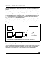
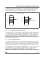
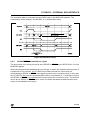
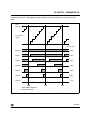
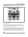
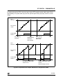
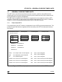
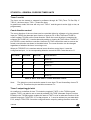
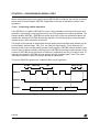
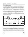
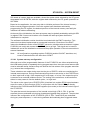
In this mode, the sequence of the transitions of the two input signals is evaluated, and
generates count pulses as well as the direction signal. So, T3 is modified automatically
according to the speed and the direction of the incremental encoder, its contents therefore
always represent the encoder’s current position.
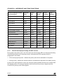
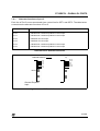
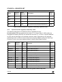
T3I
Triggering Edge for Counter Increment/Decrement
000
None. Counter stops
001
Any transition (rising or falling edge) on T3IN
010
Any transition (rising or falling edge) on T3EUD
011
Any transition (rising or falling edge) on T3 input (T3IN or T3EUD)
1XX
Reserved. Do not use this combination
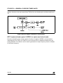
Table 34 GPT1 core timer T3 (incremental interface mode) input edge selection
198/320