1
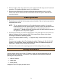
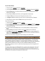
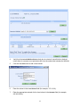
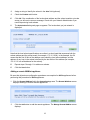
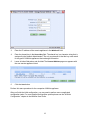
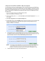
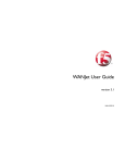
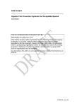
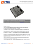
F5 WANJet 400
Quick Start Guide
Quick Start Overview
Following is a high level overview of the steps required to successfully install and configure your
F5 WANJet 400 appliance. For detailed instructions please refer to the following sections of this
guide.
1. Insert the Compact Flash card.
2. Plug both power cords into the two power ports on the back of the unit and connect each to
a separate power outlet. Press the power button on the front of the appliance.
3. Set system IP Address (default is 192.168.168.100), subnet mask (default is 255.255.255.0)
and WAN gateway IP address. These values can be set via the LCD display or through the
console port.
4. Connect the LAN switch to the LAN port and WAN router to the WAN port with the provided
Ethernet cables.
NOTE: The crossover (orange) cable should be used for connecting to the WAN router.
5. Check the license key and set any additional local subnets. Use the Optimization Policy link
in the Operational Settings area of the Web UI. Save the settings.
6. Enter a remote WANJet appliance’s IP address and shared key via the Remote WANJets link
in the System Settings area of the Web UI. Save the settings.
1
7. Login in to the Web UI for the remote appliance (other side of the WAN link) and repeat
steps 4 and 5.
Before You Begin
Before you unpack the WANJet 400 and begin setup, gather the following information.
1. An IP address and corresponding netmask that you will assign to the WANJet (for example,
172.16.1.2 with netmask 255.255.255.0).
This IP address must be in the same subnet as the WAN router that you will directly connect
to the WANJet’s WAN port.
2. The WAN router (WAN gateway) IP address.
3. If routing occurs within your local LAN, the address of your LAN next-hop router.
4. An agreed upon character string to be used as a shared key between a pair of WANJet
appliances (for example, “NYandLondon”).
Check Package Contents
Unpack the box and check the contents to make sure all parts listed below are included. If any
are missing, please contact F5 for replacement. Your WANJet 400 packaging includes the
following:
WANJet 400 Appliance
Blue CAT6 Ethernet Cable
Compact Flash Card
Documentation CD
Two Power Cords
Rack Mount Kit (includes 2 brackets and 10 screws)
Orange CAT6 Crossover Cable
This Quick Start Guide
Black Rollover (Console) Cable
Packing List (contains License Key)
DB-9 to RJ-45 Adapter
CAUTION: The motherboard on the WANJet 400 Appliance contains a replaceable CMOS
battery. If the battery is replaced with an incorrect battery type, the battery could explode.
Dispose of used batteries according to your local regulations.
Prepare for Installation
1. Insert the Compact Flash card into the slot on the rear of the appliance. Line up the arrow
on the flash card with the direction of the WANJet’s socket, and make sure that the pinned
flash tip goes into the socket. Push the flash card gently and firmly into the socket.
2
2. Select a location within easy reach of two power outlets and within easy reach of a network
connection. The location should be close to your WAN router.
3. Rack mount the WANJet 400 with the included rack mount brackets or lay it on a flat
surface. See the user manual on the documentation CD for the steps to attach the rack
mounting brackets.
Power Up the Unit
1. Plug both power cords into the two power ports on the back of the unit and connect each to
a separate power outlet.
NOTE: The two power plugs serve the unit’s redundant power supplies. It is strongly
recommended to use both power supplies. If a power cord is not connected or not
connected securely, or if a power supply fails, a warning beep will sound
continuously. To disable this sound, press the small, red reset button on the rear of
the appliance next to the power supplies.
2. Press the power button on the front of the appliance. The power light turns on and the unit
begins a hardware self-test sequence. After a few moments the system emits a beep,
indicating the hardware is operating properly.
The LCD will display WANJet Starting … for approximately 2 minutes while the system
boots up.
Once boot up is complete the LCD will display the default IP address of 192.168.168.100.
However, if your appliance address was preset at the factory, the address displayed will
match the IP address on the License Key Certificate.
3. Wait about 10 seconds for the operating system to finish loading before proceeding.
Setting the Address
Use the program buttons next to the LCD display to reset the following parameters so the
appliance can be accessed on your network. If your appliance came with the parameters
preconfigured, skip this section.
•
WANJet IP Address
•
Subnet mask
•
Default gateway
A diagram of the LCD display is shown below:
3
About the buttons:
•
Cancel (red X) button — moves through the menu options
•
Enter (green √) button—selects the currently displayed setting
•
Arrow buttons—steps through the setting
IP-format addresses are entered as a twelve-digit numbers (for example, 172.016.001.002).
When entering a portion of an IP address with less than three digits, you must include
preceding zeros. For example, if you are setting the IP address to 172.16.1.2, enter
172.016.001.002 on the LCD panel. If you make a mistake while setting the addresses, press
the red “X” button to move back to the top level of the menu, and then start over. Depending
upon where you are in the menu you may have to press the Cancel button many times to get
back to the beginning.
Set the IP Address
1. Press the Cancel (red X) button. The panel reads: Menu followed by *Setup
2. Press the Enter (green √) button. The panel reads: Setup followed by *Configure
3. Press the Enter (green √) button. The panel reads: Configure followed by *IP Address
4. Press the Enter (green √) button. The default IP address (192.168.168.100) is displayed
with a cursor blinking on the first digit.
5. Using the Up and Down arrow buttons, set the appropriate IP address. Remember, the IP
address you assign must be in the same subnet as the edge (WAN) router that you will
directly connect to the WANJet.
6. The Up and Down arrow buttons scroll through each number (0 thru9).
7. The Right and Left arrow buttons move the cursor to set each digit of the IP address.
Repeat for all digits until the IP address is correct for this WANJet appliance.
8. After setting the IP address, press the Enter button to go to the next item.
4
Set the Subnet Mask
1. The panel reads: Configure followed by *IP Address
2. Press the Down arrow button once or until panel reads: IP Address followed by *NetMask
3. Press the Enter button. The default netmask (255.255.255.0) is displayed with a cursor
blinking on the first digit.
4. Using the Up and Down arrow buttons, set the appropriate netmask value.
5. The Up and Down arrow buttons scroll through each number (0 to 9)
6. The Right and Left arrow buttons move the cursor to set each digit of the IP address.
5. After setting the netmask, press the Enter button to go to the next item.
Set the Default Gateway
1. The panel reads: IP Address followed by *NetMask.
2. Press the Down arrow button once or until the panel reads: NetMask followed by *Gateway
3. Press the Enter button. The gateway address (000.000.000.000) is displayed with a cursor
blinking on the first digit.
4. As with IP Address and NetMask above, set the default gateway IP address and press
Enter.
5. Press the Down arrow button four times or until *Apply appears on the LCD panel.
6. Press Enter (LCD panel reads: *Apply Now?). Press Enter again. In a few seconds, LCD
panel will read Config. Applied and then the LCD panel will revert to showing the WANJet IP
address (the one you configured above).
You have now successfully configured the network settings of the WANJet 400.
Deploying the WANJet 400 in a Point-to-Point Configuration
The WANJet 400 can be deployed in different network configurations (i.e., one-arm, point-topoint, redundant, and point-to-multipoint). This Guide assumes installation in a point-to-point
configuration as shown in the next figure. If you plan to deploy in any of the other configurations,
please consult the WANJet User Guide on the CD for detailed installation instructions.
Both WANJet appliances need to be cabled and configured properly before the appliance will
optimize traffic.
The diagram below shows two WANJet 400 units in a point-to-point configuration. The routers
are connected to the WAN, and the WANJet is inserted between the LAN switch/router and
WAN gateway router. The LAN port on the WANJet is connected to the LAN switch/router, and
the WAN port on the WANJet is connected to the WAN router.
5
Firewall Guidelines
If the WANJet is placed behind a firewall, the following ports should be opened to ensure proper
operation. Most should already be open except the Web UI and Local WANJet ports.
Port
Number
WANJet Web UI (TCP port)
10000
Local WANJet management (TCP port)
3701
Local WANJet tunnel (TCP port)
3702
Local WANJet tunnel (TCP port)
3703
DNS (UDP port)
53
SNMP (UDP port)
161
SNMP Traps (UDP port - optional)
162
SSH (TCP port)
22
ICMP packets (for pinging the WANJet)
N/A
6
Log on to the WANJet Web UI
Configuration and test for WANJet are done via a browser-based utility, known as the Web UI.
This section shows how to log on to the WANJet Web UI and the selection menu for all Web UI
functions.
Use these steps to log on to the WANJet Web UI.
1. Start a web browser and go to the following URL:
https://<your WANJet’s IP Address>:10000
For example, if the IP address is 192.168.168.102, go
to: https://192.168.168.102:10000
Be sure to add the “s” after http, and :10000 at the
end of the URL.
2. When this window appears, enter admin as the
username, and the default password of swanlabs.
Click Log On.
The WANJet Web UI appears and your WANJet 400
appliance is now online. Use the Web UI for all WANJet
configuration.
7
The WANJet Web UI selection
menu is shown below:
Cabling the WANJet 400
1. Connect the supplied blue Ethernet CAT6 cable to the LAN port on the front of the WANJet
400. Connect the other end to your LAN Switch.
2. Verify that the Link LED on the front panel beside the LAN Port is lit.
If the Link LED is not lit, refer to the troubleshooting section of this guide.
3. Connect the supplied orange crossover CAT6 Ethernet cable to the WAN Port on the front of
the WANJet. Connect the other end to your WAN router.
4. Verify that the Link LED on the front panel beside the WAN port is lit.
If the Link LED is not lit, refer to the troubleshooting section of this guide.
5. Make sure that this procedure is repeated for the remote WANJet appliance before you go
on to the next section.
8
Basic Configuration
To begin the configuration process, make sure you perform the basic configuration steps below.
Log in to the WANJet Web UI to perform all configuration. Refer to the section on Logon to the
WANJet Web UI for more information.
Important!
WANJet appliances are configured in pairs. You need to perform these steps for BOTH appliances in
your network (both sides of the WAN link). You can perform all configuration functions at each
appliance, or from a single machine using the Web UI.
Assume that WANJet A is connected locally and that WANJet B is connected at the remote side of
the WAN Link. Refer to the configuration diagram in the Deploying the WANJet 400 in a Point-toPoint Configuration. For this configuration, perform the general steps below:
•
On WANJet A: Verify the license key. For networks that have multiple subnets, set the local
LAN router IP address and add local subnets for WANJet A. Add WANJet B as a remote
WANJet.
•
On WANJet B: Verify the license key. For networks that have multiple subnets, set the local
LAN router IP address and add local subnets for WANJet B. Add WANJet A as a remote
WANJet.
Once the WAN link between the WANJet pair is up, subnet specifications are automatically
exchanged between the appliances. For example, the “local subnets” specified on WANJet A
are copied in as “remote subnets” for WANJet A in the configuration information on WANJet B.
Verify the License Key
The license key can be found on the Packing List included with the NC 400 package.
1. Click the Local WANJet link on the System Settings area.
2.
Verify the WANJet license key in the License Key field. The license key should match the
key on the License Key Certificate. Type in the correct license key if necessary.
3.
Enter a name for the WANJet appliance in the WANJet Alias field (optional).
4.
Click the Save button.
9
Specify the LAN Router and Add Local Subnets
Perform these steps only if you have more than one subnet in your LAN. The LAN Router refers
to the address of the next-hop router within your LAN. Check with your network administrator if
you are not sure if you need to specify additional subnets.
1. Enter the IP address of the router in the LAN Router field on the Local WANJet page shown
above.
2. Click the Save button.
3. Select the Optimization Policy link in the Operational Settings area to add local subnets.
10
4.
Verify that the Include WANJet Subnet check box is selected. Leave this box checked
unless there is a reason to not optimize traffic from the subnet that includes the WANJet.
5.
Click the first Add button to add a local subnet.
6.
Enter the subnet in the Local Subnet field (for example, 172.16.2.0).
7.
Enter the appropriate netmask for the local subnet in the Netmask field (for example,
255.255.255.0).
11
8.
Assign a string to identify the subnet in the Alias field (optional).
9.
Check the Enabled radio button.
10.
Click OK. If the combination of the local subnet address and the subnet mask do not make
sense you will receive an error message. Check with your Network Administrator if you
need help entering local subnets.
11.
The Optimization Policy web page re-appears. The local subnet you just entered is
displayed.
Note that the local subnet specifications are written in a short hand that expresses both the
subnet address and the subnet mask (for example, 172.16.1.0/24). In the example, the /24
means that the first 24 bits of the address must match the local subnet address, and the
address of any host in the subnet is defined by the last 8 bits of the address (for example,
172.16.1.6 is a valid address for the subnet).
12.
Repeat steps 5 through 11 to add more subnets.
13.
Click the Save button.
Adding a remote WANJet appliance
Be sure that all previous configuration procedures are complete for BOTH appliances before
performing this procedure for BOTH appliances.
1. Click the Remote WANJets link in the System Settings area. The Remote WANJets screen
displays showing no remote WANJet appliances.
2.
Click the Add button to add the remote appliance. The Manage Remote WANJet screen
displays.
12
3.
Enter the IP address of the remote appliance in the WANJet IP field.
4.
Enter the shared key in the Shared Key field. The shared key is a character string that is
assigned by the Network Administrator. The only requirement is that the key must match
for any pair of WANJet appliances that exchange information.
5.
Leave all other fields alone and click OK. The Remote WANJets page now appears with
the new remote appliance listed.
6.
Click the Save button.
Perform this same procedure for the companion WANJet appliance.
After you finish the initial configuration, you may need to perform more complicated
configuration tasks. For more detailed configuration options please see the “WANJet
Configuration” chapter in the WANJet User Guide.
13
Testing Connectivity
To test the connectivity between the local WANJet appliance and the remote appliances, please
perform the following steps for each appliance.
Check Status
Click the Status link at the Reports area to view the status of the remote appliances. A green
light displays next to the IP address of remote appliances that are connected.
Check Reports
If you have traffic passing through the network, click any of the throughput reports such as
Total, Sent, or Received in the Reports area. Optimized traffic reports should be available.
Check Diagnostics
Click the Diagnostics link on the Reports area, and then click the Remote WANJets link. On
the Diagnose Remote WANJets page, check the Tunnel Status of the link you want; the tunnel
status should be up.
Troubleshooting
Q. I cannot ping the WANJet appliance.
A: Make sure the computer you are pinging from has a valid network connection. Try pinging
other known devices. Go to the LCD display and make sure you have the correct IP address for
the appliance.
Q: I can ping the WANJet, but I cannot ping the WAN gateway router.
A: Re-check the cabling as described in the section Cabling the WANJet 400. Make sure the
gateway router is connected to the WANJet’s WAN port with the supplied crossover cable.
Q: I cannot see that WANJet is optimizing traffic (or the optimization is extremely low).
A: Review your configuration of local and remote subnets at BOTH appliances. You may have
heavy traffic on a subnet that is not included in the WANJet configuration. Make sure you
include all subnets for which traffic should be optimized.
14
Q: Why does the Link LED for the WAN or LAN port not light up?
A: Verify that your cables are installed properly. Next, verify that the ports on the WAN Router
and the LAN Switch connected to the WANJet are set to auto-negotiate. If either port is forced
to a specific link speed and duplex value, you will need to set the WANJet’s port to match this
value. To reset the NIC configuration (link speed and duplex value) for a WANJet port, follow
the steps below.
1. Start a web browser and go to the WANJet Web UI URL:
https://<your WANJet’s IP Address>:10000
2. At the Login dialog, enter admin as the User Name, and the default Password of swanlabs.
Click Log On.
3. Select Nic Configuration from the System Settings area.
4. Set the Media Type for the eth1 (WAN) interface that will correspond to the link between the
WANJet and the WAN router. Select the correct option from the pull-down menu (for
example, 100BaseTX Full-Duplex).
5.
Set the Media Type for the eth0 (LAN) interface that will correspond to the link between
the WANJet and the LAN switch. Select the correct option from the pull-down menu. The
speed and duplex value for LAN and WAN Media type should match.
NOTE: It is strongly recommended that if you force the link for one of the WANJet ports,
you should also force the link for the other ports. This will prevent any link
problems in passthrough mode if power to the WANJet 400 appliance is lost.
6.
Press the Save button and log off the WANJet Web UI.
15
Technical Support Information
Phone
(+1) 206-272-6888
Fax
(+1) 206-272-6802
Web
http://tech.f5.com
FTP
ftp.f5.com
E-Mail
[email protected]
For additional information, please visit http://www.f5.com
MAN-0213-00
Legal Notices
Copyright
Copyright 2005, F5 Networks, Inc. All rights reserved.
F5 Networks, Inc. (F5) believes the information it furnishes to be accurate and reliable. However, F5 assumes no
responsibility for the use of this information, nor any infringement of patents or other rights of third parties which may
result from its use. No license is granted by implication or otherwise under any patent, copyright, or other intellectual
property right of F5 except as specifically described by applicable iControl user licenses. F5 reserves the right to
change specifications at any time without notice.
Trademarks
F5, F5 Networks, the F5 logo, BIG-IP, 3-DNS, iControl, GLOBAL-SITE, SEE-IT, EDGE-FX, FireGuard, Internet
Control Architecture, IP Application Switch, iRules, OneConnect, Packet Velocity, SYN Check, Control Your World,
ZoneRunner, uRoam, FirePass, TrafficShield, WANJet and WebAccelerator are registered trademarks or trademarks
of F5 Networks, Inc. in the U.S. and certain other countries. All other trademarks mentioned in this document are the
property of their respective owners. F5 Networks' trademarks may not be used in connection with any product or
service except as permitted in writing by F5.
Patents
This product protected by U.S. Patent 6,327,242. Other patents pending.
16
17