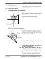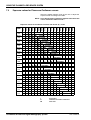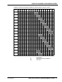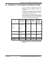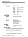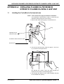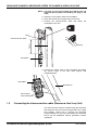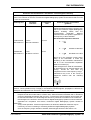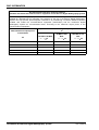
1
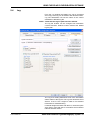
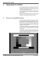
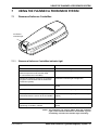
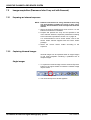
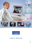
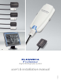
EN
Digital Radiography System
user's & installation manual
10019763_2
TABLE OF CONTENTS
1
INTRODUCTION ..............................................................................................1
1.1
1.2
1.3
2
SYSTEM REQUIREMENTS .............................................................................4
2.1
3
4.2
4.3
5.3
5.4
Image Preprocessing ................................................................................................... 19
Configuring Planmeca ProSensor settings .................................................................. 21
5.2.1 Auto exposure threshold values (Ethernet interface) .......................................... 21
Configuring ProSensor ethernet interface .................................................................... 22
Log ............................................................................................................................... 23
IMAGE QUALITY CONTROL .........................................................................24
6.1
7
PC configuration ............................................................................................................ 8
4.1.1 Disabling proxy server .......................................................................................... 8
4.1.2 Changing the computer IP address .................................................................... 10
Planmeca ProSensor configuration utilities ................................................................. 13
4.2.1 Changing the ControlBox IP-address ................................................................. 14
4.2.2 Updating the ControlBox software ...................................................................... 16
Resetting the IP Address ............................................................................................. 17
USING THE DIDAPI CONFIGURATION SOFTWARE ..................................18
5.1
5.2
6
Ethernet interface connection ........................................................................................ 5
USB interface connection .............................................................................................. 7
CONFIGURING PLANMECA PROSENSOR DIGITAL RADIOGRAPHY
SYSTEM ...........................................................................................................8
4.1
5
Planmeca Romexis computer requirements .................................................................. 4
PLANMECA PROSENSOR SYSTEM SETUP FOR ETHERNET &
USB INTERFACE .............................................................................................5
3.1
3.2
4
Symbols ......................................................................................................................... 1
Notes, cautions and warnings ........................................................................................ 1
Package contents for Ethernet / USB interface ............................................................. 3
1.3.1 Ethernet interface .................................................................................................. 3
1.3.2 USB interface ........................................................................................................ 3
Quality check using SMPTE test pattern ..................................................................... 24
USING THE PLANMECA PROSENSOR SYSTEM .......................................25
7.1
7.2
7.3
Planmeca ProSensor ControlBox ................................................................................ 25
7.1.1 Planmeca ProSensor ControlBox indicator light ................................................ 25
Image acquisition (Planmeca Intra X-ray unit with Romexis) ....................................... 26
7.2.1 Preparing an intraoral exposure .......................................................................... 26
7.2.2 Capturing Intraoral Images ................................................................................. 26
7.2.3 Patient positioning ............................................................................................... 31
7.2.4 Positioning the sensor ......................................................................................... 31
Exposure values for Planmeca ProSensor sensors ..................................................... 32
8
SENSOR HOLDERS ......................................................................................34
9
CLEANING .....................................................................................................35
9.1
9.2
9.3
9.4
Surfaces ....................................................................................................................... 35
Sensors and cables ..................................................................................................... 35
Sensor holders ............................................................................................................. 36
Planmeca ProSensor ControlBox ................................................................................ 36
User’s & Installation Manual
Planmeca ProSensor Digital Radiography System 1
TABLE OF CONTENTS
10
DISPOSAL OF THE PLANMECA PROSENSOR SYSTEM ..........................37
11
TECHNICAL SPECIFICATIONS ....................................................................38
APPENDIX A: INSTALLING PLANMECA PROSENSOR SYSTEM TO
PLANMECA INTRA X-RAY UNIT ..................................................................39
1.1
1.2
Installing the ControlBox to the bracket arm ................................................................ 39
Connecting the interconnection cable (Planmeca Intra X-ray Unit) ............................. 40
APPENDIX B: EMC INFORMATION .............................................................41
The manufacturer, assembler, and importer are responsible for the safety, reliability and
performance of the unit only if:
- installation, calibration, modification and repairs are carried out by qualified authorized personnel
- electrical installations are carried out according to the appropriate requirements such
as IEC364
- equipment is used according to the operating instructions
Planmeca pursues a policy of continual product development. Although every effort is
made to produce up-to-date product documentation this publication should not be
regarded as an infallible guide to current specifications. We reserve the right to make
changes without prior notice.
COPYRIGHT PLANMECA 2009-06
Publication number 10019763 Version 2
2 Planmeca ProSensor Digital Radiography System
User’s & Installation Manual
INTRODUCTION
1
INTRODUCTION
This manual describes how to use and install the
Planmeca ProSensor Digital Radiography System.
Please read this manual carefully before using and
installing the system. See also Planmeca Intra X-ray unit
user’s manual.
NOTE The Planmeca Intra X-ray unit and Romexis software
have separate user’s manuals, which should be used
in conjunction with this manual.
1.1
Symbols
Type BF equipment (Standard IEC 878).
The use of accessory equipment not complying with the
equivalent requirements of this equipment may lead to a
reduced level of safety of the resulting system.
Consideration relating to the choice shall include:
- use of the accessory in the Patient Vicinity
- evidence that the safety certification of the accessory
has been performed in accordance to appropriate
IEC60601 and/or IEC60601-1-1 harmonized national
standard.
Planmeca ProSensor Digital Radiography System is
supplied with the UL Recognition mark.
1.2
Notes, cautions and warnings
NOTE The system should be installed and operated by
qualified personnel only.
NOTE EMC requirements have to be considered, and the
equipment must be installed and put into service
according to the specific EMC information provided in
the accompanying documents.
CAUTION Handle the Planmeca ProSensor Digital
Radiography System according to the
instructions given in this manual. Do not
pinch the sensor or the cable. Do not to drop
the sensor or pull strongly the sensor cable.
Never cut, nick or sharply bend the sensor
cable. Always advise the patient not to bite
the sensor or the cable. The Planmeca
limited warranty does not cover damage
which is due to misuse, e.g. dropping the
sensor, neglect, or any cause other than
ordinary application.
CAUTION Do not let the sensor cable run along the
floor. Protect the cable from rolling over it
with a chair or walking over it.
User’s Manual
Planmeca ProSensor Digital Radiography System 1
INTRODUCTION
CAUTION Do not store or use the Planmeca Sensor
near (3m or 10 ft) an electrosurgical knife.
WARNING
Do not unnecessarily touch
connector pins to keep them clean.
2 Planmeca ProSensor Digital Radiography System
the
User’s Manual
INTRODUCTION
1.3
Package contents for Ethernet / USB interface
1.3.1
Ethernet interface
1. Packing list
2. Sensor holder package
3. Romexis Software package
4. ProSensor User’s/Installation Manual
5. PoE port with power cable
1.3.2
6. Interconnection cable RJ45
7. Interconnection cable RJ45
8. ProSensor Ethernet ControlBox
9. ProSensor with cable
10. Sensor hanger
USB interface
1. Romexis Software package
2. Sensor holder package
3. ProSensor User’s/Installation Manual
4. Sensor hanger
User’s Manual
5. ProSensor USB ControlBox
6. Packing list
7. ProSensor with cable
Planmeca ProSensor Digital Radiography System 3
SYSTEM REQUIREMENTS
2
SYSTEM REQUIREMENTS
NOTE The PC and other equipment connected to the system
must be:
- approved by local authorities: e.g. IEC-approved (CE
marked), UL / CSA approved
- located outside the patient area (more than 2m (79
in.) from the X-ray unit)
- protectively earthed.
NOTE The connection of additional equipment to a multiple
portable socket-outlet must only be possible by using
a tool or be supplied via separating transformer.
NOTE The multiple portable socket-outlets shall not be
placed on the floor.
NOTE Make sure that the system is protected with firewall
and up to date anti-virus software. If possible, isolate
the system from office network.
2.1
Planmeca Romexis computer requirements
Planmeca Romexis
client work station
Planmeca Romexis
database server
Processor
1 GHZ
2 GHZ
RAM
1 GB
2 GB minimum
Hard disk space
40 GB or more
160 GB or more recommended
Graphics card
128 minimum memory
128 minimum memory
Monitor
1280 x 1024
1280 x 1024
Peripherals
CD-ROM drive
CD-ROM drive
Backup medium
None necessary
DAT or equivalent
Operating system
Other
Windows XP, 2003, Vista,
Mac OS X Linux
Mac OS / Linux support subject to
contract
Java platform (Java Virtual
Machine 1.6 or later)
4 Planmeca ProSensor Digital Radiography System
Windows XP Pro, Windows
2003 Server, Vista
Java platform (Java Virtual
Machine 1.6 or later)
User’s Manual
PLANMECA PROSENSOR SYSTEM SETUP FOR ETHERNET & USB INTERFACE
3
PLANMECA PROSENSOR SYSTEM SETUP FOR
ETHERNET & USB INTERFACE
3.1
Ethernet interface connection
The Planmeca ProSensor ControlBox must be installed
so that the sensor can be easily placed in the the patient’s
mouth and that the input cable from the PoE (Power over
Ethernet) port will reach the socket in the back of the PC.
NOTE The PoE port must comply with IEEE 802.3af standard
NOTE Only equipment complying with IEC/EN 60950 must be
connected to the ethernet connector.
NOTE The ethernet cables must be connected to ethernet
sockets only. Do not connect the cables to any other
equipment.
NOTE Ethernet connection has two LED indicator lights.
Green light signifies “100 baseTx link on” and yellow
“Communication active”
NOTE The distance between PoE port and ControlBox must
not exceed 100 m.
1. Connect the Ethernet cable from the PC / LAN network to
the input socket of the PoE port. If necessary a hub can
be connected between the PC and the PoE port.
2. Connect the Ethernet cable from the PoE output socket to
the ControlBox).
3. Connect the ProSensor cable to the ControlBox. The PoE
port can be installed in the same space with the Hub/
Ethernet switch or next to the ControlBox.
The control box must be installed so that no liquid will spill
on it.
Typical network configuration
1
Romexis
ProSensor
Kytkentakuva2.eps
Control box
Max. 100m
Ethernet
Max. 100m
PoE
OUT
100 - 240VAC
User’s Manual
IN
HUB
or
Ethernet switch
Planmeca ProSensor Digital Radiography System 5
PLANMECA PROSENSOR SYSTEM SETUP FOR ETHERNET & USB INTERFACE
Typical standalone configuration
Romexis
ProSensor
Kytkentakuva2.eps
Control box
Max. 100m
Ethernet
PoE
OUT
IN
Max. 100m
100 - 240VAC
Connecting Planmeca ProSensor ControlBox to PoE (Power over Ethernet port)
2
ProSensor
with cable
PoE port
ProSensor
ControlBox
Ethernet cables
6 Planmeca ProSensor Digital Radiography System
User’s Manual
PLANMECA PROSENSOR SYSTEM SETUP FOR ETHERNET & USB INTERFACE
3.2
USB interface connection
The Planmeca ProSensor ControlBox must be installed
so that the sensor can be easily placed in the patient’s
mouth and that the cable of the USB hub will reach the
socket in the back of the PC.
NOTE The USB cable must be connected to USB sockets
only. Do not connect the cables to any other
equipment.
NOTE If the distance between the Control box and the PC
exceeds 5 m a HUB must be used.
1. Connect the ControlBox USB cable to the PC.
Alternatively a hub can be connected between the PC and
the ControlBox.
2. Connect the magnetic connector of the Planmeca
ProSensor to the ControlBox.
1
Romexis
ProSensor
Kytkentakuva_usb.eps
Control box
max 5m
Fixed 2 or 5m
Alternative connection max 5m
USB HUB
User’s Manual
Planmeca ProSensor Digital Radiography System 7
CONFIGURING PLANMECA PROSENSOR DIGITAL RADIOGRAPHY SYSTEM
4
CONFIGURING PLANMECA PROSENSOR DIGITAL
RADIOGRAPHY SYSTEM
4.1
PC configuration
4.1.1
Disabling proxy server
The following example describes the configuration
performed with the Internet Explorer 7 browser. However,
configuration can be performed with any browser.
1. To access the ProxyServer settings click Tools on your
browser window. .
2. On the appearing menu select Internet Options.
8 Planmeca ProSensor Digital Radiography System
User’s Manual
CONFIGURING PLANMECA PROSENSOR DIGITAL RADIOGRAPHY SYSTEM
3. On the Connections tab click Lan Settings.
4. The following window opens. Disable proxy server by
unchecking the Proxy server tickbox. Click OK.
User’s Manual
Planmeca ProSensor Digital Radiography System 9
CONFIGURING PLANMECA PROSENSOR DIGITAL RADIOGRAPHY SYSTEM
4.1.2
Changing the computer IP address
The PC IP address must be changed to the same IP
space with the Control box so that the ControlBox can be
configured.
1. Click on windows Start menu and select Control Panel
10 Planmeca ProSensor Digital Radiography System
User’s Manual
CONFIGURING PLANMECA PROSENSOR DIGITAL RADIOGRAPHY SYSTEM
2. The Control Panel window opens. Click Network and
Internet connections.
3. In the Network Connections window right-click the Local
Area connection icon and select Properties.
User’s Manual
Planmeca ProSensor Digital Radiography System 11
CONFIGURING PLANMECA PROSENSOR DIGITAL RADIOGRAPHY SYSTEM
4. Scroll down the menu and select Internet Protocol (TCP/
IP). Click Properties.
5. Select Use the following IP address and change your
computer IP settings to same IP space with the default
ControlBox IP address 172.26.150.150. The address
must not be identical with the ConrolBox IP address.
Click OK.
12 Planmeca ProSensor Digital Radiography System
User’s Manual
CONFIGURING PLANMECA PROSENSOR DIGITAL RADIOGRAPHY SYSTEM
4.2
Planmeca ProSensor configuration utilities
On the Planmeca ProSensor main page you will find
utilities for:
•
Changing the Planmeca ProSensor IP adress
•
Updating the ControlBox software
To access the Planmeca ProSensor main page:
1. Type the IP address of the controlbox and /index.html in
the address field of the browser e.g. http://
172.26.150.150/index.html. If the address has been
modified it might be different from the adress of this
example. Make sure to type in the latest configured
address of the control box.
2. The following window opens:
User’s Manual
Planmeca ProSensor Digital Radiography System 13
CONFIGURING PLANMECA PROSENSOR DIGITAL RADIOGRAPHY SYSTEM
4.2.1
Changing the ControlBox IP-address
1. Click the link Change IP-address.
2. Browser goes to http://172.26.150.150/netcfg.asp and the
following window opens.
3. The default IP-address for each ControlBox is
172.26.150.150. To change the ControlBox IP address
type the new IP address, Subnet Mask and Default
Gateway in the corresponding fields and click Send.
4. Wait until the ControlBox indicator light switches from
yellow to blue.
5. Reboot the ControlBox by unpluging and repluging the
ControlBox cable.
6. Change the computer IP address back to original (for
more information see section “Changing the computer IP
address” on page 10 ).
14 Planmeca ProSensor Digital Radiography System
User’s Manual
CONFIGURING PLANMECA PROSENSOR DIGITAL RADIOGRAPHY SYSTEM
7. Change the new Controlbox IP to DidapiConfiguration
(please see section “Configuring Planmeca ProSensor
settings” on page 21“).
To test the ControlBox connection:
1. Open the Command Prompt window via Windows Start
menu by selecting All Programs > Accessories >
Command Prompt.
2. Type command ping and the new ControlBox IP address
in the command prompt window.
User’s Manual
Planmeca ProSensor Digital Radiography System 15
CONFIGURING PLANMECA PROSENSOR DIGITAL RADIOGRAPHY SYSTEM
4.2.2
Updating the ControlBox software
1. Select Upload ControlBox SW.
2. Browser goes to http://172.26.150.150/upload.asp. To
select a new software version click Browse and Send.
3. Wait until the ControlBox indicator light goes from yellow
to blue and reboot the ControlBox.
16 Planmeca ProSensor Digital Radiography System
User’s Manual
CONFIGURING PLANMECA PROSENSOR DIGITAL RADIOGRAPHY SYSTEM
4.3
Resetting the IP Address
NOTE The following procedure will reset the IP address,
Subnet Mask and the Default Gateway only.
1. Switch on the power of the ControlBox
2. To access the reset button detach the bottom cover of the
ControlBox by pushing the lock buttons on both sides of
the ControlBox with your fingers.
3. At the bottom of the ControlBox a small hole can be seen.
To reset the default IP address insert an appropriate tool
into the hole pushing it to the bottom.
4. The ControlBox indicator light starts to flash in yellow
before switching to steady. Next, the steady green light
comes on and switches to steady blue. This will take a
few seconds.
5. Lift out the tool and reboot the ControlBox by unplugging
and replugging the ControlBox cable.
6. Open the DidapiConfig software (see chapter 5 “USING
THE DIDAPI CONFIGURATION SOFTWARE” on page
18).
7. Click Open ProSensorEthernetConfig.txt and enter the
required information. By clicking the Refresh button the
modifications will be updated in the address fields.
User’s Manual
Planmeca ProSensor Digital Radiography System 17
USING THE DIDAPI CONFIGURATION SOFTWARE
5
USING THE DIDAPI CONFIGURATION SOFTWARE
The Didapi Configuration is used to configure and monitor
Planmeca device drivers. The DIDAPI Configuration
software is automatically installed with the Romexis
software.
1. Open the DIDAPI Configuration software by clicking
Start> Programs> Planmeca> Didapi Configuration.
2. The DIDAPI Configuration tool will start and the System
Info window appears.
18 Planmeca ProSensor Digital Radiography System
User’s Manual
USING THE DIDAPI CONFIGURATION SOFTWARE
5.1
Image Preprocessing
In this tab the parametres for intraoral images can be
adjusted.
If the option Auto Levels Enabled is selected automatic
adjustment is performed on the image when a new image
is taken. In the White(%)(high) and Black(%)(low) fields
percentage of the image tones to be cut in the ends of the
histogram can be adjusted in order to gain reasonable
contrast.
The Midtones value affects the gamma curve of the
image. By adjusting the gamma value, you get an image
that looks more like a conventional X-ray image.
By enabling the FMH filter an image can be filtered and
sharpened.
For Logarithmic Mapping adjustment tick the respective
checkbox and select the appropriate parameter from the
drop-down menu. The logarithmic S-curves increases the
contrast in the region of interest without clipping low or
high values.
DICE (Dental Imaging Contrast Enhancement) is an
image preprocessing method that suppresses low spatial
frequencies in the image to bring out details in the image.
You can set DICE on or off separately for different image
modalities by checking the respective check box.
If the settings have been changed, the Apply button
becomes active. To save the changed values click Apply.
The recommended default settings can be restored by
clicking the corresponding Set Defaults button.
Clicking OK quits the program and saves any changes
made to the settings. Clicking Cancel quits the program
without saving the changes.
User’s Manual
Planmeca ProSensor Digital Radiography System 19
USING THE DIDAPI CONFIGURATION SOFTWARE
The preprocessing performed by DIDAPI is permanent
and can not be undone by Romexis. For more information
on image preprosessing refer to Romexis Installation
manual.
20 Planmeca ProSensor Digital Radiography System
User’s Manual
USING THE DIDAPI CONFIGURATION SOFTWARE
5.2
Configuring Planmeca ProSensor settings
5.2.1
Auto exposure threshold values (Ethernet interface)
If the Planmeca ProSensor Digital Radiography System is
used with some other intra oral X-ray unit than Planmeca
Intra the sensor threshold values can be adjusted for the
used X-ray unit. Change these values only if necessary.
The threshold value affects the detection sensitivity of the
the start of exposure. Increase the threshold value if the
sensor appears to be too sensitive, i.e. it triggers and
takes exposures without radiation. Decrease the value if
the sensor fails to detect an exposure.
If the settings have been changed, the Apply button
becomes active. To save the new values click Apply. The
factory default values can be restored by clicking the
respective Set Defaults button.
Clicking OK quits the program and saves any changes
made to the settings. Clicking Cancel quits the program
without saving any changes.
User’s Manual
Planmeca ProSensor Digital Radiography System 21
USING THE DIDAPI CONFIGURATION SOFTWARE
5.3
Configuring ProSensor ethernet interface
The ProSensor Ethernet Interface can be configured in
the Ethernet Interface tab .
NOTE Make sure that the configuration file path is defined as
C:\Program Files\Planmeca\Dimaxis\Program\. If not,
click Browse to select the correct path.
To perform the configuration:
1. Enter the ControlBox IP Address in the correct field and
click Apply.
2. The default IP adress is 172.26.150.150, see also
paragraphs 4.2.1 “Changing the ControlBox IP-address”
on page 14 and 4.3 “Resetting the IP Address” on page
17.
3. Alternatively you can leave the IP Address field empty
and enter the network name in the Network name field. It
is not necessary to enter the IP address as well as the
network name; by entering the IP address you will obtain
the network name, and vice versa. All IP addresses do not
necessarily have a network name.
NOTE When using Planmeca ProSensor in the same PC with
Dixi PCI or USB interface, imaging is performed with
the Dixi sensor even though the Planmeca ProSensor
has been configured. Choosing Dixi Ethernet will
affect imaging only if Dixi Ethernet interface is being
used.
22 Planmeca ProSensor Digital Radiography System
User’s Manual
USING THE DIDAPI CONFIGURATION SOFTWARE
5.4
Log
From the Log window the Didapi Log can be accessed
and a copy of the log can be saved to the desired location.
Log File Workstation ID sets the name of the current
workstation’s DIDAPI log file.
NOTE Check that the log file path has been defined.
The log file location can be changed from Alternative
Location Browser. Default Location restores the default
log file path.
The Log level setting determines how much information
will be written to the log file. The Log level should be set to
Normal. If set to Full it might be hard to find relevant
information for troubleshooting.
If intraoral images are taken with this PC, check the option
Intra Sensor used with this PC and select the ProSensor
Ethernet intraoral sensor.
User’s Manual
Planmeca ProSensor Digital Radiography System 23
IMAGE QUALITY CONTROL
6
IMAGE QUALITY CONTROL
Verify the image quality after installing the software and
before patient exposure. Perform quality control check
according to the requirements of local authorities, using
for example Quart phantom or similar.
It is recommended to regularly monitor the image quality
using the same phantom according to the requirements of
local authorities.
Before performing phantom exposures verify that the
brigthness and contrast settings of the monitor are
accurate by using a SMPTE test pattern or similar.
6.1
Quality check using SMPTE test pattern
The test image is specified by the Society of Motion
Picture and Television Engineers (www.smpte.org), and
follows the SMPTE Recommended Practise RP 133-1991
Specifications for Medical Diagnostic Imaging Test
Pattern for Television Monitors and Hard-Copy Recording
Cameras. This image should be used for monitor setting
and quality checks performed:
- Before every working day: The 5% gray field inside the
0% field and the 95% gray field inside the 100% field
should be visible. If not, adjust the brightness and contrast
of the monitor.
- Every month: The line raster in the corners and in the
center must be visible, the vertical and horizontal lines
must form undistorted squares and the homogenous gray
background must not be coloured.
24 Planmeca ProSensor Digital Radiography System
User’s Manual
USING THE PLANMECA PROSENSOR SYSTEM
7
USING THE PLANMECA PROSENSOR SYSTEM
7.1
Planmeca ProSensor ControlBox
ProSensor
indicator light
ps
2.e
ox_
l_b
tro
con
7.1.1
Planmeca ProSensor ControlBox indicator light
PLANMECA PROSENSOR STATUS
Planmeca ProSensor system power off
controlbox indicator light is off
Planmeca ProSensor system is off (not in
intraoral exposure-mode and the cable
controlbox indicator light is dim blue
is connected to the ControlBox)
Planmeca ProSensor system is on (Imaging
program communicates with the Planmeca
ProSensor system)
controlbox indicator light is bright blue
Waiting for Ready
controlbox indicator light is blue and flashing
slowly
Waiting for Exposure
controlbox indicator light is green and steady
The exposure is taken and image is
transferred from the sensor to the ControlBox
controlbox indicator light is green and flashing
rapidly
Error-mode
controlbox indicator light is red and steady
Service mode
controlbox indicator light is yellow and flashing
slowly
Uploading ControlBox software
NOTE The exposure can only be taken when the indicator
light on the Planmeca ProSensor ControlBox is green
and steady, not when the indicator light is flashing.
User’s Manual
Planmeca ProSensor Digital Radiography System 25
USING THE PLANMECA PROSENSOR SYSTEM
7.2
Image acquisition (Planmeca Intra X-ray unit with Romexis)
7.2.1
Preparing an intraoral exposure
NOTE Detailed instructions for using Planmeca Intra X-ray
unit and Romexis software are given in their user’s
manual, which should be used in conjunction with this
manual.
1. Select the desired CMOS-sensor and connect it to the
Planmeca ProSensor ControlBox.
2. Prepare and position the X-ray unit as specified in the
user’s manual. Select the exposure parameters according
to the instructions specified in section 7.3 on page 32.
It is recommended to use a sensor holder, refer to the
sensor holder manual supplied with the sensor holder
package.
3. Select the correct sensor holder according to the
exposure.
7.2.2
Capturing Intraoral Images
Intraoral images can be captured either as single images
or into study templates containing a predefined set of
multiple images.
Single images
1. To capture an intraoral image click the Intraoral Exposure
button on the upper toolbar to initiate the intraoral image
capture mode.
Intraoral Exposure
2. The Intraoral Exposure window appears.
26 Planmeca ProSensor Digital Radiography System
User’s Manual
USING THE PLANMECA PROSENSOR SYSTEM
3. When the X-ray unit is in ready state a message Waiting
for Ready appears on top of the window.
4. Prepare the patient for exposure, select exposure
parameters and position Planmeca Intra as required, for
more information refer to Planmeca Intra user’s manual.
When the Planmeca ProSensor system is ready for
exposure the message Waiting for Exposure appears on
top of the window. You can now expose the X-ray as
usual. After the exposure a message stating Saving the
image appears on the display and the image is
automatically stored into the database.
5. Define the tooth numbers and sensor orientation and take
the next exposure, or click Done to return to the Imaging
module when all exposures have been captured.
User’s Manual
Planmeca ProSensor Digital Radiography System 27
USING THE PLANMECA PROSENSOR SYSTEM
Template images
To capture intraoral images into a study template click this
button.
1. Select the desired study template from the list.
At the beginning of the list there are empty templates and
at the bottom of the list there are studies with dates that
already include images captured earlier.
28 Planmeca ProSensor Digital Radiography System
User’s Manual
USING THE PLANMECA PROSENSOR SYSTEM
While capturing images using a study, Romexis navigates
through the template in a predefined order, denoting the
current image to be captured by a blue border around the
slot.
2. Follow the tooth numbering and sensor orientation as
shown on the image and predefined in the template.
User’s Manual
Planmeca ProSensor Digital Radiography System 29
USING THE PLANMECA PROSENSOR SYSTEM
To cancel the process click the Cancel button. The
captured images are saved and the incomplete study is
preserved for later use.
3. Once all images have been captured click Done.
30 Planmeca ProSensor Digital Radiography System
User’s Manual
USING THE PLANMECA PROSENSOR SYSTEM
7.2.3
Patient positioning
Ask the patient to sit down. Place a protective lead apron
over the patient’s chest.
7.2.4
Positioning the sensor
Paralleling technique (recommended)
The sensor is placed to a sensor holder which is used to
align the sensor parallel to the long axis of the tooth.
Use a long cone for the paralleling technique.
Long axis
of the tooth
Sensor
Bisecting angle technique (optional)
The patient holds the sensor in place with his finger. The
X-ray beam is directed perpendicularly towards an
imaginary line which bisects the angle between the film
plane and the long axis of the tooth.
Long axis
of the tooth
Sensor
The use of the plastic cover is not necessary because the
sensor can be sterilized with liquid. The sterilization must
be done after each patient.
NOTE Be very careful not to put excessive pressure on the
sensor. Do not place a clamp on the sensor. Do not
take occlusal exposures with the sensor, and advise
the user not to bite the sensor.
NOTE Never clamp the sensor package or cable with a
hemostat or an unmodified “Snap-a-ray” holder.
Make sure the Planmeca ProSensor system is ready for
the exposure and communicates with Romexis (refer to
section 7.1 “Planmeca ProSensor ControlBox” on page
25.
On how to place the sensor into the patient’s mouth refer
to the sensor holder manual supplied with ProSensor.
User’s Manual
Planmeca ProSensor Digital Radiography System 31
USING THE PLANMECA PROSENSOR SYSTEM
7.3
Exposure values for Planmeca ProSensor sensors
Select the digital imaging mode of the unit or adjust the
exposure time according to the table.
NOTE In the digital imaging mode the highest time value that
can be selected is 0.80 seconds.
child
I
63 kV/
child
I
P
M
I
P
60 kV/
child
I
57 kV/
child
55 kV/
child
52 kV/
child
50 kV/
child
70 kV/
adult
I
I
P
66 kV/
adult
63 kV/
adult
60 kV/
adult
57 kV/
adult
55 kV/
adult
52 kV/
adult
50 kV/
adult
I
I
P
M
32 Planmeca ProSensor Digital Radiography System
0.80s
0.64s
0.50s
0.40s
0.32s
0.25s
0.20s
0.16s
0.12s
0.05s
maxilla
mandible
M
maxilla
mandible
P M
maxilla
M
mandible
I
P M
maxilla
P M
mandible
I
P M
maxilla
I
P M
mandible
I
P M
maxilla
I
P M
mandible
I
P M
maxilla
I
P M
mandible
I
P M
maxilla
I
P M
mandible
P M
maxilla
M
mandible
I
P M
maxilla
P M
mandible
I
P M
maxilla
I
P M
mandible
I
P M
maxilla
I
P M
mandible
I
P M
maxilla
I
P M
mandible
I
P M
maxilla
I
P M
mandible
I
P M
maxilla
I
P M
mandible
I
P M
maxilla
I
P M
mandible
66 kV/
0.10s
0.04s
child
0.08s
0.03s
P
M
I
P
M
I
I
P
70 kV/
0.06s
0.02s
TIME
0.01s
Exposure values for ProSensor sensors with 20 cm (8”) cones
INCISORS
PREMOLARS AND CANINES
MOLARS
User’s Manual
USING THE PLANMECA PROSENSOR SYSTEM
63 kV/
child
I
P
M
I
P
60 kV/
child
I
57 kV/
child
55 kV/
child
52 kV/
child
50 kV/
child
70 kV/
adult
I
I
P
66 kV/
adult
I
63 kV/
adult
60 kV/
adult
57 kV/
adult
55 kV/
adult
52 kV/
adult
50 kV/
adult
I
P
M
User’s Manual
0.80s
0.64s
0.50s
0.40s
maxilla
mandible
M
maxilla
mandible
P M
maxilla
M
mandible
I
P M
maxilla
P M
mandible
I
P M
maxilla
I
P M
mandible
I
P M
maxilla
I
P M
mandible
I
P M
maxilla
I
P M
mandible
I
P M
maxilla
I
P M
mandible
P M
maxilla
M
mandible
I
P M
maxilla
P M
mandible
I
P M
maxilla
I
P M
mandible
I
P M
maxilla
I
P M
mandible
I
P M
maxilla
I
P M
mandible
I
P M
maxilla
I
P M
mandible
maxilla
I
P M
I
P M
mandible
maxilla
I
P M
mandible
I
P M
I
0.32s
0.10s
child
0.25s
0.08s
P
M
I
P
66 kV/
0.20s
0.06s
child
0.16s
0.05s
I
P
M
I
70 kV/
0.12s
0.04s
0.03s
0.02s
TIME
0.01s
Exposure values for Planmeca ProSensor sensors with 30 cm (12”) cones
INCISORS
PREMOLARS AND CANINES
MOLARS
Planmeca ProSensor Digital Radiography System 33
SENSOR HOLDERS
8
SENSOR HOLDERS
The sensor holders provide an easy way to position the
sensor for different anatomical and diagnostic needs. For
instructions how to use the sensor holders, please refer to
the manual supplied with the sensor holder package.
34 Planmeca ProSensor Digital Radiography System
User’s Manual
CLEANING
9
CLEANING
NOTE Before cleaning the system, always check that the Xray unit and the Planmeca ProSensor system are off
(Planmeca ProSensor ControlBox indicator light is
off).
9.1
Surfaces
The surfaces can be cleaned with a soft cloth dampd in a
mild cleaning solution.
Stronger cleaning agents can be used for disinfecting the
surfaces. We recommend Dürr System-hygiene FD 333
or respective disinfecting solution.
9.2
Sensors and cables
Planmeca ProSensor sensors allow enhanced infection
control in the surgery.
As the sensor casing is hermetically sealed the sensors
can be immersed in disinfectant solution.
NOTE Always use appropriate instruments for cleaning the
sensors.
NOTE It is mandatory to carefully follow the disinfecting and
cleaning recommendations in order to not damage the
sensors.
CAUTION The sensors cannot
autoclave or UV oven.
be
sterilized
in
Wipe up the sensor surface with a soft cloth damped into
a disinfectant solution. The sensors can be soaked in a
disinfection solution as long as there are no nicks in the
cable.
The recommendable disinfectant solutions are Dürr
System Hygiene FD 322 or FD 333 or similar product. The
immersion time with the Dürr disinfectants is 2 minutes.
If more effective disinfection or cold sterilization is
preferred
for
cleaning,
we
recommend
the
Johnson&Johnson Cidex Opa high level disinfectant at a
minimum temperature of 20° C with maximum immersion
time of 8 minutes for a reuse period not to exceed 14
days.
NOTE Follow carefully the manufacturer’s recommendations
on immersion time and recommended disinfectant
liquids.
Do not leave the sensor in the disinfection solution
overnight. The magnetic connector of the sensor cable
should not be soaked.
User’s Manual
Planmeca ProSensor Digital Radiography System 35
CLEANING
•
Use a new disposable protection cap for every sensor
usage.
•
Wipe up the sensor surface with a compress moisten
into a sterile solution.
NOTE The sensor connector can be cleaned using a soft
cloth.
9.3
Sensor holders
For cleaning the sensor holders refer to the manual
supplied with the sensor holder package.
9.4
Planmeca ProSensor ControlBox
The ControlBox can be cleaned with a soft cloth damped
in a mild cleaning solution.
CAUTION Switch off the unit before cleaning.
NOTE Do not disinfect the unit.
36 Planmeca ProSensor Digital Radiography System
User’s Manual
DISPOSAL OF THE PLANMECA PROSENSOR SYSTEM
10
DISPOSAL OF THE PLANMECA PROSENSOR SYSTEM
In order to reduce the environmental load over the
product’s entire lifecycle, PLANMECA’s products are
designed to be as safe as possible to manufacture, use
and dispose of.
Parts which can be recycled should always be taken to
the appropriate processing centres, after hazardous
waste has been removed. Disposal of obsolete systems is
the responsibility of the waste possessor.
All parts and components containing hazardous materials
must be disposed of in accordance with waste legislation
and instructions issued by the environmental authorities.
The risks involved and the necessary precautions must be
taken into account when handling waste products.
Part
Main materials
for disposal
Recyclable
material
Waste
disposal
site
Hazardous
waste
(separate
collection)
ControlBox
- metal
stainless steel
X
- plastic
ASA + PC
X
POM
X
Cables
PC
X
PU
X
copper
X
TPE/PU
Packing
X
cardboard,
X
paper,
X
PE foam
X
Sensors
Return the sensors to Planmeca.
Other parts
PoE
X
NOTE If the component boards cannot be recycled handle
them as electronic scrap, i.e. according to the local
legislation.
User’s Manual
Planmeca ProSensor Digital Radiography System 37
TECHNICAL SPECIFICATIONS
11
TECHNICAL SPECIFICATIONS
Sensor
Sensor type
CMOS with scintillator
Sensor dimensions:
Size 0
overall
active area
number of pixels
view delay
33.6 x 23.4 mm (1.33 x 0.92 in.)
25.5 x 18.9 mm (1,00 x 0,74 in.)
850 x 629
<5 sec.
Size 1
overall
active area
number of pixels
view delay
39.7 x 25.05 (1.56 x 0.99 in.)
31.5 x 20.7 (1.24 x 0.81 in.)
1050 x 690
<5 sec.
Size 2
overall
active area
number of pixels
view delay
44.1 x 30.4 mm (1,74 x 1.2 in.)
36 x 26.1 mm (1,74 x 1,2 in.)
1200 x 870
<5 sec.
Resolution
17 lp/mm
Theoretical resolution
33 lp/mm
Cable length
0.86 m (33.9 in.) or 2.0 m (78.7 in.)
Ethernet ControlBox
Dimensions
112 x 46 x 24 mm (4.41 x 1.81 x 0.94 in.)
Power supply
48 V DC 65 mA
Cables
ControlBox to PoE
RJ45 10m OR 15m
PoE to LAN
RJ45 10m OR 15m
Power supply
Phihong Single Port Injector
Type: PSA16U-480 (POE)
Input voltage 100-240 VAC (50-60 Hz)
Output voltage 48VDC
Max. output current 0.35 A
Insulation voltage
Primary-secondary 3000VDC
USB ControlBox
Dimensions
112 x 46 x 24 mm (4.41 x 1.81 x 0.94 in.)
Cables
fixed USB 2.0 power supply cable 2 or 5m
(6.6 or 16.4 ft)
Operating environment
Prior to installation of the system check that the local conditions are compatible with the
appliance design.
The temperature of the operating environment should be between + 15°C and + 40°C
The relative humidity of the operating environment should not exceed 60 %.
Transportation and Storage Environment
Transportation and storage temperature -5°C - +60°C.
Relative humidity during transportation and storage should not exceed 60 %.
38 Planmeca ProSensor Digital Radiography System
User’s Manual
INSTALLING PLANMECA PROSENSOR SYSTEM TO PLANMECA INTRA X-RAY UNIT
APPENDIX A: INSTALLING PLANMECA PROSENSOR
SYSTEM TO PLANMECA INTRA X-RAY UNIT
1.1
Installing the ControlBox to the bracket arm
NOTE These instructions apply for Ethernet installation.
The ProSensor interconnection cable is routed into the
Planmeca Intra bracket arm at the factory.
1. Remove the cable opening plug on the bracket arm.
Plug
Opening for the
interconnection cable
Intradj4.eps
ProSensor interconnection cable
Bracket arm
2. Pull out the interconnection cable for approx. 19 cm (7.5
in.) as shown in the figure below.
19cm
Interconnection
cable
3. To ensure that the interconnection cable moves freely as
the bracket arm moves, route the cable through the
bracket arm as shown in the following figure.
4. Cut the plug and attach it to the cable. Reattach the plug
to the bracket arm opening.
User’s Manual
Planmeca ProSensor Digital Radiography System 39
INSTALLING PLANMECA PROSENSOR SYSTEM TO PLANMECA INTRA X-RAY UNIT
NOTE The plug is cut on the rounded end. Remove the cap
from the opening before assembling the plug to the
cable.
5. Attach the velcro tapes under the ControlBox.
6. Clean the bracket arm properly with pure alcohol.
7. Connect the interconnection cable and attach the
ControlBox to the arm.
Plug
19cm
Interconnection cable
Opening
ControlBox
8. Connect the sensor cable to the ControlBox and attach
the sensor holder to the tube head support with
doublesided tape.
ControlBox
Bracket arm
Velcro tapes
and counterparts
1.2
Connecting the interconnection cable (Planmeca Intra X-ray Unit)
The interconnection cable is routed through the Planmeca
Intra extension arm and out from the generator box, single
stud adapter, ceiling arm or through the Planmeca
Compact dental unit. For more information see Planmeca
Intra X-ray unit installation manual, publication number
10006030.
40 Planmeca ProSensor Digital Radiography System
User’s Manual
EMC INFORMATION
APPENDIX B: EMC INFORMATION
WARNING
Use of any accessories and cables other
than those specified in ProSensor Digital
Radiography System documentation,
with exception of cables sold by
Planmeca as replacement parts for
internal components, may result in
increased
emission
or
decreased
immunity of the system
WARNING
ProSensor Digital Radiography System
should not be used adjacent to or
stacked with other equipment. If adjacent
or stacked use is necessary, the
ProSensor Digital Radiography System
should be observed to verify normal
operation in configuration which it will be
used.
Guidance and manufacturer’s declaration electromagnetic emissions
ProSensor Digital Radiography System is intended for use in the electromagnetic environment
specified below. The customer or the user of the ProSensor Digital Radiography System should
assure that it is used in such an environment.
Emissions test
Compliance
RF emissions
Group 1
CISPR 11
RF emissions
Class B
CISPR 11
Harmonic emissions
Not Applicable
Electromagnetic environment – guidance
ProSensor Digital Radiography System uses RF
energy only for its internal function. Therefore, its
RF emissions are very low and are not likely to
cause any interference in nearby electronic
equipment.
ProSensor Digital Radiography System is
suitable for use in all establishments, including
domestic establishments and those directly
connected to the public low-voltage power supply
network that supplies buildings used for domestic
purposes.
IEC 61000-3-2
Voltage fluctuations/
flicker emissions
Not Applicable
IEC 61000-3-3
User’s Manual
Planmeca ProSensor Digital Radiography System 41
EMC INFORMATION
Guidance and manufacturer’s declaration - electromagnetic immunity
ProSensor Digital Radiography System is intended for use in the electromagnetic environment specified
below. The customer or the user of ProSensor Digital Radiography System should assure that it is used in
such an environment.
Immunity test
Electrostatic
discharge (ESD)
IEC 60601
test level
Compliance level
±6 kV contact
±6 kV contact
±8 kV air
±8 kV air
Electrical fast
transient/burst
±2 kV for power
supply lines
Not Applicable
IEC 61000-4-4
±1 kV for input/output
lines
±1 kV for input/output
lines
Surge
±1 kV line to line
Not Applicable
IEC 61000-4-5
±2 kV line to earth
Not Applicable
Voltage dips, short
interruptions and
voltage variations
on power supply
input lines
<5 % UT
(>95 % dip in UT)
for 0,5 cycle
Not Applicable
IEC 61000-4-2
IEC 61000-4-11
40 % UT
(60 % dip in UT)
for 5 cycles
70 % UT
(30 % dip in UT)
for 25 cycles
<5 % UT
(>95 % dip in UT)
for 5 s
Power frequency(
50/60 Hz)
magnetic field
3 A/m
3 A/m
IEC 61000-4-8
Electromagnetic environmentguidance
Floors should be wood, concrete
or ceramic tile. If floors are
covered with synthetic material,
the relative humidity should be
at least 30%.
Mains power quality should be
that of a typical commercial or
hospital environment
Mains power quality should be
that of a typical commercial or
hospital environment.
Mains power quality should be
that of a typical commercial or
hospital environment. If the user
of
ProSensor
Digital
Radiography System requires
continued
operation
during
power mains interruptions, it is
recommended that ProSensor
Digital Radiography System be
powered from an uninterruptible
power supply.
Power frequency magnetic fields
should be at levels characteristic
of a typical location in a typical
commercial
or
hospital
environment.
The
power
frequency magnetic field should
be measured in the intended
installation location to assure
that it is sufficiently low.
NOTE UT is the a.c. mains voltage prior to application of the test level.
42 Planmeca ProSensor Digital Radiography System
User’s Manual
EMC INFORMATION
Guidance and manufacturer’s declaration - electromagnetic immunity
ProSensor Digital Radiography System is intended for use in the electromagnetic environment specified
below. The customer or the user of ProSensor Digital Radiography System should assure that it is used
in such an environment.
Immunity test
IEC 60601
test level
Compliance
level
Electromagnetic environmentguidance
Portable and mobile RF communications
equipment should be used no closer to any
part of the ProSensor Digital Radiography
System, including cables, than the
recommended
separation
distance
calculated from the equation applicable to
the frequency of the transmitter.
Conducted RF
3 Vrms
IEC 61000-4-6
150 kHz to 80 MHz
Radiated RF
3 V/m
IEC 61000-4-3
80 MHz to 2.5 GHz
3 Vrms
Recommended separation distance
d = 1,2 P
d = 1,2 P
80 MHz to 800 MHz
d = 2,3 P
800 MHz to 2.5 GHz
3 V/m
where P is the maximum output power
rating of the transmitter in watts (W)
according to the transmitter manufacturer
and d is the recommended separation
distance in metres (m).
Field strengths from fixed RF transmitters,
as determined by an electromagnetic site
survey,a should be less than the
compliance level in each frequency range.b
Interference may occur in the vicinity of
equipment marked with the following
symbol:
NOTE 1: At 80 MHz and 800 MHz, the higher frequency range applies.
NOTE 2: These guidelines may not apply in all situations. Electromagnetic propagation is affected by
absorption and reflection from structures, objects and people.
a
Field strengths from fixed transmitters, such as base stations for radio (cellular/cordless)
telephones and land mobile radios, amateur radio, AM and FM radio broadcast and TV broadcast
cannot be predicted theoretically with accuracy. To assess the electromagnetic environment due
to fixed RF transmitters, an electromagnetic site survey should be considered. If the measured
field strength in the location in which ProSensor Digital Radiography System is used exceeds the
applicable RF compliance level above, ProSensor Digital Radiography System should be
observed to
verify normal operation. If abnormal performance is observed, additional measures may be
necessary, such as re-orienting or relocating ProSensor Digital Radiography System.
b
Over the frequency range 150 kHz to 80 MHz, field strengths should be less than 3 V/m.
User’s Manual
Planmeca ProSensor Digital Radiography System 43
EMC INFORMATION
Recommended separation distances between
portable and mobile RF communications equipment and ProSensor Digital Radiography System
ProSensor Digital Radiography System is intended for use in an electromagnetic environment in which
radiated RF disturbances are controlled. The customer or the user of ProSensor Digital Radiography
System can help prevent electromagnetic interference by maintaining a minimum distance between
portable and mobile RF communications equipment (transmitters) and the ProSensor Digital
Radiography System as recommended below, according to the maximum output power of the
communications equipment.
Rated maximum output power
of transmitter
W
Separation distance according to frequency of transmitter
m
150 kHz to 80 MHz
d = 1,2 P
80 MHz to 800
MHz
800 MHz to 2.5
GHz
d = 1,2 P
d = 2,3 P
0.01
0.2
0.2
0.3
0.1
0.4
0.4
0.7
1
1.2
1.2
2.4
10
4.0
4.0
8.0
100
12.0
12.0
24.0
44 Planmeca ProSensor Digital Radiography System
User’s Manual
Planmeca Oy | Asentajankatu 6 | 00880 Helsinki | Finland
tel. +358 20 7795 500 | fax +358 20 7795 555 | [email protected] | www.planmeca.com