1
AcNet Pro 4x4
Access Control System
controller
Installation
Manual
IMPORTANT NOTICE
All information and data contained in this document is proprietary and confidential. CROW Electronic Engineering Ltd. shall not be liable, in any event, for any claims for damages or any other remedy in any
jurisdiction whatsoever, whether in an action in contract, tort (including negligence and strict liability) or any other theory of
liability, whether in law or equity including, without limitation, claims for damages or any other remedy in whatever jurisdiction,
and shall not assume responsibility for patent infringements or other rights to third parties, arising out of or in connection with
this document. Further, CROW Electronic Engineering Ltd. reserves the right to revise this publication and to make changes
to its content, at any time, without obligation to notify any person or entity of such revision changes. These materials are
copyrighted and any unauthorized use of these materials may violate copyright, trademark, and other laws. Therefore, no part
of this publication may be reproduced, photocopied, stored on a retrieval system, or transmitted without the express written
consent of CROW Electronic Engineering Ltd. Any new issue of this document invalidates previous issues.
© CROW Electronic Engineering Ltd. 2005, 2006. All rights reserved.
Information in this document is subject to change without notice. No part of this document may be reproduced or transmitted
in any form or by any means, electronic or mechanical, without express written permission of CROW Electronic Engineering
Ltd.ACTEC Series
P/N 7102004 Rev.A.
2
The AcNetPro 4x4 Installation Manual
September 2008
TABLE OF CONTENTS
1. INTRODUCTION................................................................................................................................................. 4
2. THE ELECTRONIC BOARD AND THE PCB JUMPERS.......................................................................................... 5
3. POWER SOURCES AND BOARD CONSUMPTION.............................................................................................. 6
4. CARD READERS TYPE AND CONNECTION....................................................................................................... 7
4.1 Connecting the Proximity Reader Range.................................................................................................. 7
4.2 Connecting four readers without extension board:................................................................................. 8
4.3 Connecting four readers with an extension board EXT-84 or EXT-TCPT84:............................................ 8
5. DOOR CONTACTS AND INPUTS DEVICES......................................................................................................... 9
6. LOCK DEVICE - RELAY OUTPUTS CONNECTION............................................................................................... 9
7. EXTENSION BOARDS....................................................................................................................................... 10
8. RS232 / RS485 SERIAL PORT CONNECTION..................................................................................................11
8.1 RS232 port. Jumpers JP1:.........................................................................................................................11
8.2 RS485 port. Jumpers JP1 :.......................................................................................................................11
8.3 Protection against RFI interferences:......................................................................................................12
8.4 Setting the controller address.................................................................................................................12
9.0 Alarm Inputs.................................................................................................................................................13
9.1 Output Relays...........................................................................................................................................13
APPENDIX A : THE 10 COMMANDMENTS OF THE INSTALLER...........................................................................14
HOW TO CONTACT US..........................................................................................................................................15
The AcNetPro 4x4 Installation Manual
3
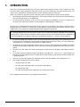
1. INTRODUCTION.
AcNet series, are all based on microprocessors. They are installed in order to operate 24 hours a day. In addition, since they
must often control a given environment, AcNet series may be connected to various types of exterior elements such as card
readers, electrical door opener, alarm detection device, printer, mainframe computer and so forth.
Under such circumstances, this kind of system is subjected to some extremely difficult constraints directly related to :
1.
Electro Magnetic Interferences (EMI) along the lines connecting the terminal to any exterior elements. Undesired voltage
may reach thousands of volts in case of lightnings.
2.
The exterior elements themselves. In most cases, they are not supplied by CROW but are chosen in response to the
constraints of the particular installation site (local distributors, national operating standards, etc.).
All AcNet series is provided with internal protection devices against all such interference. (These devices include varistances,
protection diodes, etc.). However, since AcNet series may be installed in a variety of operating environments, there are a certain
number of basic rules of thumb that should be followed in order to provide extra protection.
It is absolutely imperative that, from the moment a AcNet series is installed, the individual responsible for the installation
rigorously adhere to all the directives listed below. Should any of these directives not be rigorously adhered to, CROW will not
assume responsibility for any problems or malfunctions that might be encountered as a result of such non-compliance.
1.
The control unit (housing the microprocessor) must never be installed inside a high voltage electrical power box and must
never be placed in close proximity to large transformers or high voltage/current source devices. Since the controller may
require maintenance, it is important to consider the accessibility of the unit.
2.
The board must be separately grounded. Therefore, one must verify in advance whether the installation site provides
adequate grounding facilities. Verification can be carried out by measuring the 220/110 volts between the phase and the
ground.
3.
The cover or case that contains the control unit housing the microprocessor must be tightly screwed down or locked in
place.
4.
It is essential to plug the AcNetPro terminal's 220/110 volt sector cable into a "clean" line (i.e., a line not being used
other pieces of heavy equipment) or into an independant line, which has been specifically allocated to the terminal, with
a good earth ground.
5.
Never use the system cables guide to pass wires from another system, like loud bells, electric door openers, etc ...
6.
Four categories of cable go to, or from, the terminal:
−
The 220/110 volt sector cable
−
The cables connecting badge-readers, alarm entries and push-buttons
−
The communication cable
−
The cable connecting the electrical door opener or an exterior release device
These categories must be installed as far as possible one from the other.
4
The AcNetPro 4x4 Installation Manual
J1
Serial port
Buz2o
Dat2o
Clk2o
Buzz2
Lon2
Led5
Led4
J2a
Door 2
(Exit)
Tx
Rx
RS485
RS232
JP1
Dat2/I10
Clk2/I9
J2
Door 2 (Entrance)
J4
Door 1 (Entrance) Door 1 (Exit)
12Vdc
0v J7
Vcc
0v
Rx/L
0v
J1a
Tx/H
Buz1o
Dat1o
Clk1o
Buzz1
Lon1
Led2
Led1
Dat1/I12
Clk1/I11
Vcc
0v
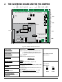
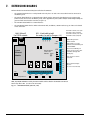
2.THE ELECTRONIC BOARD AND THE PCB JUMPERS
R3c
RL3
Extension Board:
12 relays
Or 8 inputs/4 relays/TCP/IP
See par.7
R3no
R2c
R2nc
R2no
RL1
-
R1c
R1no
0v
I8
ROM
on
I7
Eprom
I6
DS2
Bat
JP3
8
JP4
0v
0v
I3
I2
Tx Rx
J6B
I1
H2
:
L2
Lithium
Cell
J10 : 2 comm.
Port
on
J6A
I5
I4
nd
Driver
RS485/2
Reset
Alarm Input indicators :
Off if input closed.
UART/2
R eset led: Off during reset
1
J5B
R1nc
CPU
4
J5A
R3nc
RL2
1
R4nc
R4no
RL4
Driver
RS485/1
14,8 cm.
R4c
0v
15,8 cm.
Fig. 1: The AcNetPro 4x4 Electronic board
J1/J1a: Readers
Entrance/Exit Door 1
SWITCHES DS2:
DS2/1: Reserved
DS2/2: off: Led1/Led2 for green/red Leds of Readers 1 and 1a
J1/J1a: Readers
Entrance/Exit Door 2
Led4/Led5 for green/red Leds of Readers 2 and 2a
On: Led1/Led2/Led4/Led5 for green leds of readers
1/1a/2/2a.
DS2/3: Not used
DS2/4 on: Readers with Wiegand Interface
J4 : Serial Port
RS232 or RS485
J5A, J5B : 4 Relays
24v / 1A
J6A, J6B :
8 Alarme inputs
J7 : Power
10Vdc to 13Vdc/0,5A
J10: Second serial port
(Driver RS485/2 and UART/2 must
be installed)
JP3: Lithium Cell on/off
Do not remove
SWITCHES JP4:
AcNetPro:
JP4/1-5 : Controller Address (see par. 8.4)
JP4/6,7,8 : Readers Technology :
6 on: Wiegand (Up to 50 bits) with parity check (set also
DS2/4 to ‘on’)
7 on: Wiegand (Up to 50 bits) without parity check (set
also DS2/4 to ‘on’)
8 on: not in use
Note 1: For the Wiegand Interface only : Set switch
DS2/4 ON.
Note 2 : reader type PR use blue Led (not Red Led)
The AcNetPro 4x4 Installation Manual
JP1: Selection
RS232/RS485:
654
654
:::
:::
RS232
RS485
12 3
123
5
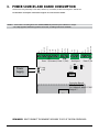
3. POWER SOURCES AND BOARD CONSUMPTION
The board must be powered by 12Vdc. Nude, without any card reader, the board consumption is 100 mA max.
The maximum consumption authorised through the Vcc of the board is 300 mA.
Notes: 1- Card readers consuming more than 250mA CANNOT be powered by the AcNetPro Vcc output.
J1
J1a
Serial port
RS485
RS232
JP1
12Vdc
0v J7
Led5
Led4
Dat2/I10
Clk2/I9
Vcc
J2
J4
Door 1 (Entrance) Door 1 (Exit)
Power
Supply
0v
Rx/L
Tx/H
0v
Buz1o
Dat1o
Clk1o
Buzz1
Lon1
Led2
Led1
Dat1/I12
Vcc
Clk1/I11
2- A safety approved 12V battery pack has to be used, according to the local standards.
0v
Door 2 (Entrance)
Tx
Rx
Driver
RS485/1
Extension Board:
12 relays
Or 8 inputs/4 relays/TCP/IP
See par.7
CPU
14,8 cm.
ROM
on
1
Eprom
4
DS2
UART/2
R eset led: Off during reset
1
Reset
Lithium
Alarm Input i
Off if inp
J10 : 2nd c
Port
on
:
JP3
6
8
Driver
RS485/2
RemindeR! DON’T CONNECT THE READER’S
WIRE TO VCC OF THE PCB CONTROLLER.
CellRED Bat
JP4
The AcNetPro 4x4 Installation Manual
15,8 cm.
Tx Rx
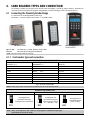
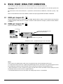
4. CARD READERS TYPES AND CONNECTION
The AcNetPro controller may recognise many kind of reader technologies, selected by jumpers JP4/6,7,8. Hereunder the
connection for the most popular one (magnetic and proximity). For other technologies, refer to the relevant manual.
4.1 Connecting the Proximity Reader Range
It is adviced to use the ACTEC proximity reader range.
PR 103/104 – a 125 KHz models or smart reader – a 13,56 MHz model
PR 104 Anti Vandal
PR 103 Prox
PR 106 Prox Pincode
Type of cable:
8 shielded wires, 22 AWG. Maximum length: 100m.
Interface:
ISO2 (clock/data) or Wiegand (data0/data1)
SW - 7 Fingerprint (refer to the
relevant Manual)
NOTE : connection readers table on next page
4.1.1 Card readers type and connection
PR TYPE READERS - CABLE CONNECTION
Reader / ISO2 Interface
(Proxpoint, etc…)
Reader / Wiegand Interface
(PR 03/04/06, etc..)
ACNET 200 PCB
Reader 1/2
+DC
+DC
Red
12Vdc
GROUND
GROUND
Black
0v
CLOCK
DATA 0
Green
CLK1/CLK2
DATA
DATA 1
White
DAT1/DAT2
DATA RTN (If exists)
DATA RTN
GREEN LED (If exists)
BLUE LED
RED LED (If exists)
GREEN LED Orange
Brown
0v
LED1/LED4
BEEPER (If exists)
BEEPER
BUZ1/BUZ2
Yellow
Fig 3. connection readers table
Note 2 : Refer to the reader manufacturer instruction manual for reader operation detail
AcNetPro Dip switches DS1
ISO 2 INTERFACE (Clock/Data) :
Any Wiegand card
6 50 bits with
6 parity
6
up to
7
7
7
checking
based
on
ISO2
format.
8
8
8
6
7
8
off
WIEGAND INTERFACE (See also note 1 below) :
on
DS1
off
on
DS1
off
off
on
on
DS1DS1
6
7
8
off
Any Wiegand card
up to 506bits 6with parity
7
7
checking based
8
8 on format:
PE
….
Data
bits
off on
off off
on
on ….PO
on
6
7
8
DS1DS1
DS1DS1
6
7
8
off
on
Any Wiegand card
up to 50 bits without
parity checking
DS1
Fig 3. setup of DS1 switch
NOTE! Bfore connecting the PR 106 – make sure to reprogram it to Motorola output signal.
Read PR 106 instruction for details.
The AcNetPro 4x4 Installation Manual
7
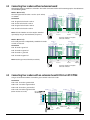
4.2 Connecting four readers without extension board:
AcNetPro 4x4 allows to control four card readers. The readers connection and the Leds functionning may be selected between
the two following modes:
Reader 1
Reader 1o
Connection:
0v
Vcc
Clock
Data
Green Led
Red led
Led ON
Buzzer
Reader 2
0v
Vcc
Clock
Data
Green Led
Red led
Led ON
The red and green leds of readers 1 and 1o (and 2 and 2o)
are common.
Buzzer
Mode 1 (DS2/2 ‘off’):
Reader 2o
0v
Vcc
Green Led
Red Led
Led On
Clock
Data
Buzzer
0v
Vcc
Green Led
Red Led
Led On
Clock
Data
Buzzer
'Led1' for green leds of reader 1 and 1o.
'Led2' for red leds of reader 1 and 1o.
'Led4' for green leds of reader 2 and 2o.
Reader 1
Reader 1o
Clk 2o
Dat 2o
Buz 2o
Buzzer
Buzzer
Reader 2
0v
Vcc
Clock
Data
Green Led
Red led
Led ON
Connection:
J 2a
Reader 2o
Reader 2
Connection example for 4 magnetic
card readers in Mode 1
DS2
Each reader green led is independantly controlled. The reader
red leds are not used.
J2
Reader 1o
on
2
Mode 2 (DS2/2 ‘on’):
0v
Vcc
Clk 2/I9
Dat 2/I10
Led 4
Led 5
Lon 2
Buzz 2
J 1a
J1
Reader 1
0v
Vcc
Clock
Data
Green Led
Red led
Led ON
Note: The leds of Readers 1o and 2o may be controlled
separately by using an extension board (See par.4.3).
Clk 1o
Dat 1o
Buz 1o
0v
Vcc
Clk 1/I11
Dat 1/I12
Led 1
Led 2
Lon 1
Buzz 1
'Led5' for red leds of reader 2 and 2o.
Reader 2o
0v
Vcc
Green Led
Red Led
Led On
Clock
Data
Buzzer
0v
Vcc
Green Led
Red Led
Led On
Clock
Data
Buzzer
'Led1' for reader 1 green led.
'Led2' for reader 1o green led.
'Led4' for reader 2 green led.
J 1a
J1
Reader 1
J2
Reader 1o
Clk 2o
Dat 2o
Buz 2o
0v
Vcc
Clk 2/I9
Dat 2/I10
Led 4
Led 5
Lon 2
Buzz 2
Note: Readers type PR use blue led (not red led).
Clk 1o
Dat 1o
Buz 1o
0v
Vcc
Clk 1/I11
Dat 1/I12
Led 1
Led 2
Lon 1
Buzz 1
'Led5' for reader 2o green led.
J 2a
Reader 2o
Reader 2
on
2
Connection example for 4 magnetic
card readers in Mode 2
DS2
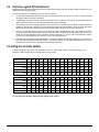
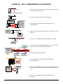
4.3 Connecting four readers with an extension board EXT-84 or EXT-TCPT84:
Using an extension board allows to control the green and Red leds of each reader.
Connection:
'Led1'/'Led2' for reader 1 green/red led.
'Led6'/'Led7' for reader 1o green/red led.
(DS2/2 must be set to 'off')
Reader 1
EXT -84 or EXT TCPT84 Board
0v
Vcc
Clock
Data
Green Led
Red led
Led ON
Buzzer
'Led8'/'Led9' for reader 2o green/red led.
0v
Vcc
Clock
Data
Green Led
Red led
Led ON
Buzzer
'Led4'/'Led5' for reader 2 green/red led.
Reader 2
Reader 1o
Reader 2o
0v
Vcc
Green Led
R ed Led
Led On
Clock
Data
Led6
Led7
Led8
Led9
0v
Vcc
Green Led
R ed Led
Led On
Clock
Data
Buzzer
Buzzer
2
J1
DS2
8
Reader 1
The AcNetPro 4x4 Installation Manual
J1a
AcNetPro Board
Reader 1o
J2
Reader 2
Clk2o
Dat2o
Buz2o
0v
Vcc
Clk2/I9
Dat2/I10
Led4
Led5
Lon2
Buzz2
Clk1o
Dat1o
Buz1o
off
0v
Vcc
Clk1/I11
Dat1/I12
Led1
Led2
Lon1
Buzz1
J27
J2a
Reader 2o
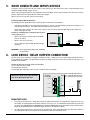
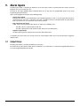
5. DOOR CONTACTS AND INPUTS DEVICES
A magnetic contact, passive infra-red unit, request to exit switch or any other form of dry contact can be monitored via the
AcNetPro controller through 8 inputs I1 to I8.
Inputs I1 to I4 are supervised inputs: they control the contact itself (Open or close) and also the line (line short or cut). For this
purpose, Two resistors must be installed as shown on the diagram.
Inputs I5 to I8 are 2 states only. (contact close or open)
Protection against RFI interferences:
The following must be rigidly adhered to, in order to prevent malfunctions or interruptions :
−
If the distance between the alarm detector, push-button, etc., and the electronic board is greater than 10 meters, use a
shielded cable and connect the shields to the ground point of the control unit.
−
Always ensure that a distance of at least 50 cm, separates the connecting cables from both high-tension cables and
electrical door opener cable.
Example of a Normally Open or Normally Closed switch
connected to input I1.
−
J6B
Inputs I1 to I4 may be supervised (use 2x4,7KOhms
resistors as shown).
0v
I4
I3
−
Inputs I5 to I8 are 2 states only.
−
Use a 2 conductors wire 22 AWG. Maximum lenght:
100 meters
AcNetPro
Controller
I2
4,7 Kohms
I1
4,7K
0v
WARNING! - Do not apply voltage higher than 30VAC/DC
to alarm inputs.
6.LOCK DEVICE - RELAY OUTPUTS CONNECTION
The Four relays on the controller can support a maximum of 24V @ 1 Amp. Do not try to switch higher voltage than this as
it may damage the controller. See figure below, for details of wiring an electronic release. The function of each relay is user
definable in the software.
Example of wiring an electronic release on relay No.1
Use a 2 conductors wire 18 AWG.
Standard length : 10 meters.
For more than 10m, depends on wire resistance and load current consumption.
Always fit a Diode across a DC electronic
lock, to be fitted at the lock end.
AcNetPro
Controller
R#no : Normally Open contact
RL4
Relais 4
J5A R#nc : Normally Closed contact
R4c
R#c : Common contact of relay
R4nc
RL3
Relais 3
R4no
R3c
R3nc
RL2
R3no
J5B
R2c
Relais 2
RL1
Relais 1
0v +12v
R2nc
R2no
R1c
R1nc
R1no
+•
•-
Important notes:
1.
If the release mechanism has a charge that exceeds the authorised limit or has a strong inductive charge (as in the case,
for example, of revolving doors or turnstiles), it will be necessary to use an intermediate relay between the system and
the charge. THE CHARGE MUST BE POWERED WITH A SEPARATE POWER SUPPLY. The intermediate relay and the electronic
board may be powered with the same power supply, the one of the board for example.
2.
The cable connecting the release mechanism to the control unit (or to the intermediate relay) must be isolated, and there
must therefore be a distance of at least 50 cm, between this cable and all the other cables.
The AcNetPro 4x4 Installation Manual
9
7. EXTENSION BOARDS
Different kinds of extension boards may be installed on the AcNetPro:
−
The 'EXT-RLY' board which is a 12 relays board. Each relay has a 'Co' and a 'No' contact which must be connected as
described in par.6.
−
The 'EXT-84' board which has 8 supervised inputs (which must be connected as described in par.5), 4 output relays
(which must be connected as described in par.6), and 4 supplementary leds (Led6 to led9) to control independantly the
green and Red leds of readers 1o and 2o (see par. 4.3).
−
The 'EXT-TCPT' board which has a TCP/IP interface.
−
The 'EXT-TCPT84' board which is similar to the EXT-84 with, in addition, a TCP/IP interface. Fig.7.1 shows such a board
and its connection.
Led9
Led8
ER EG
Led7
J27: 4 leds Led6 to Led9
for readers 1o and 2o (See par. 4. 3 )
Rx
J27
Led6
RJ45 (10BaseT)
For TCP/IP network
Led6: Rdr. 1o Green ('Pass') led
Led7: Rdr. 1o Red ('Fail') led
Led8: Rdr. 2o Green ('Pass') led
Led9: Rdr. 2o Red ('Fail') led
Tx
J28: RS485 port from
J28
RS485
Hi
Lo
SR
SG
Hole for fixation
screw on the
AcNetPro board.
TCP/IP
Ethernet
Module
J25
0v
I16
I15
I14
I13
TCP/IP network.
When TCP/IP is used, the
AcNetPro on-board RS485 port
is not available.
This ext. board RS485 port
may be used to connect other
controllers (through their
RS485 port).
Refer to par. 8.3 for line
protection.
0v
0v
I12
I11
J25: 8 supervised Inputs
I9 to I16.
(See Par. 5 for connection)
I10
SW2
I9
J26
0v
R8no R8c R7no R7c R6no R6c R5no R5c
R8nc
R7nc
R6nc
R5nc
Relay indicators:
SW2, SR, SG, ER and EG are used by the TCP/IP module and described in the Module User Manual.
J26: 4 relays RL5 to RL8 (See Par. 6 for connection).
Fig. 7.1 - 'EXT-TCPT84' Board (9,90 x 12,1 cm)
10
The AcNetPro 4x4 Installation Manual
8. RS232 / RS485 SERIAL PORT CONNECTION.
If the controller has to be connected to a PC at less than 30 meters, its RS232 port may be used.
If the distance is bigger than 30 meters or if several controllers must be connected together to a PC, the RS485 port must be
used as follows.
The characteristics of the serial transmission is : asynchronous serial transmission, 4800 bauds, 8 data bits, no parity, 1 stop
bits.
With an on-board firmware version from 1/4/2002, the baud rate may be programmable from 4800 to 38400 baud.
654
654
8.1 RS232 port. Jumpers JP1: :::
:::
1 2 322 or 24 AWG.
1 2Maximum
3
The three signals 0v, Rx andTx (3 shielded wire
distance: 30m) are connected to the PC (or the printer)
as follows: AcNetPro-JP4/0v to D25/Pin 7 or D9/pin 5, AcNetPro -JP4/Rx to D25/Pin 2 or D9/pin 3, AcNetPro -JP4/Tx to D25/Pin
3 or D9/pin 2.
654
654
123
123
::: JP1 : :::
8.2 RS485 port. Jumpers
Connect the controllers as follows:
Port COM on PC :
D9
Connect the cable shield only at the
RS 232/RS 485 interface.
3
2
5
Rx
Tx
0v
RS232
RS 232/RS 485
Interface
L
H
RS485
120 Ohms
Connect the interface to a good earth
RS485 bus: 1,2 Km. Shielded twisted pair cable 22/24 AWG
1 off
2 off
3 off
4 off
JP4 5 off
JP1
6
7
AcNetPro
8
Tx/H Rx/L
:::
Address 0
1 on
2 off
3 off
4 off
JP4 5 off
JP1
6
7
AcNetPro
8
Tx/H Rx/L
:: :
Address 1
Tx/H Rx/L
:::
JP4
JP1
AcNetPro
1 on
2 on
3 on
4 on
5 off
6
7
8
Address 15
Tx/H Rx/L
:::
JP4
JP1
AcNetPro
1 on
2 on
3 on
4 on
5 on
6
7
8
Address 31
Notes:
1-Do not connect the communication cable screen at any point other than at the RS232/RS485 interface end.
2- It is imperative that the interface has a good earth ground through the mains. The importance of a good earth ground cannot
be overemphasized. Performance of the protection is directly related to the efficiency of the grounding system.
3- When one RS485 bus is used as shown in the schema, two end of line resistors (120 ohms) must be installed, one at the
RS232/RS485 interface and one at the last controller of the bus.
4- Each AcNetPro board must have its own address selected by jumpers JP4/1-5, as shown below.
The AcNetPro 4x4 Installation Manual
11
8.3 Protection against RFI interferences:
Most of the interference will come by induction to the cable shield, on which high and very high voltage may appear because
of RFI interferences or lightning bolts.
To prevent perturbations, the following rules must then be respected:
1.
Use a shielded 22AWG triple-wire cable ("Receive"/"Transmit"/0v) for the RS232 connection and use a shielded 22 AWG
twisted pair cable for the RS485 connection.
2.
A good quality cable shield must be used and the shield must be connected to a strong earth. The shield should be from
copper rather than aluminium, since the latter provides only partial attenuation.
3.
All communication cable shieldings should be connected to only one extremity (and not both), in order to avoid the
problem of "ground loops". Whereas the connection for the RS485 wire shield should be carried out at the level of the
concentrator and the connection for the RS232 wire shield should be carried out at the level of the terminal.
4.
A distance of at least 50 cm must separate all such connecting cables from high-tension cables, from cables connected to
an electrical power box controlled by the system, or from any cables capable of generating strong interference (such as
cables connected to high-power motors, generators, wireless telephone, etc.). Since it is often located besides a variety
of cables, the external telephone line can also be a source of strong interference.
5.
Extremely high tension produced by lightning bolts can enter the terminals through these above lines. Such tension can
reach the level of hundreds of thousands of volts. It is therefore advised to use the CROW SP200 protection unit at the
AcNetPro level. (This protection is included in the RS232/RS485 interface)
8.4 Setting the controller address.
In order to programme the system, each controller has to have a unique address which is defined with jumpers JP4:
AcNetPro is addressed from 00 to 31 through jumpers JP4/1 to JP4/5.
AcNetPro address:
00
01
02
03
04
05
06
07
08
09
10
11
12
13
14
15
JP4/1 Off
On
Off
On
Off
On
Off
On
Off
On
Off
On
Off
On
Off
On
JP4/2 Off
Off
On
On
Off
Off
On
On
Off
Off
On
On
Off
Off
On
On
JP4/3 Off
Off
Off
Off
On
On
On
On
Off
Off
Off
Off
On
On
On
On
JP4/4 Off
Off
Off
Off
Off
Off
Off
Off
On
On
On
On
On
On
On
On
JP4/5 Off
Off
Off
Off
Off
Off
Off
Off
Off
Off
Off
Off
Off
Off
Off
Off
16
17
18
19
20
21
22
23
24
25
26
27
28
29
30
31
JP4/1 Off
On
Off
On
Off
On
Off
On
Off
On
Off
On
Off
On
Off
On
JP4/2 Off
Off
On
On
Off
Off
On
On
Off
Off
On
On
Off
Off
On
On
JP4/3 Off
Off
Off
Off
On
On
On
On
Off
Off
Off
Off
On
On
On
On
JP4/4 Off
Off
Off
Off
Off
Off
Off
Off
On
On
On
On
On
On
On
On
JP4/5 On
On
On
On
On
On
On
On
On
On
On
On
On
On
On
On
AcNetPro address:
Fig. 8.4 Setting the controller address through jumpers JP4/1 to JP4/5.
12
The AcNetPro 4x4 Installation Manual
9.Alarm Inputs
According to the model, a controller gets between 4 to 16 alarm inputs to which any kind of detectors may be connected
(magnetic contact, passive infra-red, etc.).
The mode of each input (Normally Open or Normally Close) and its time zone are programmable. (Refer to the system
Programming Manual for details)
Inputs may be programmed to operate in the following modes:
−
General alarm inputs
During the time zone it is armed (defined by its Event Weekly Programme), as soon as an alarm input switches from its
normal state to its active state, a ‘start alarm’ transaction is recorded in the transaction buffer. When the input switches
back to its normal state, an “end of alarm” transaction is recorded.
−
Door contact for door alarm
A door contact connected to door input will raise an alarm in the 2 following cases:
- The door is forced, i.e. opened with no valid card.
- The door is opened with a valid card but left open more than a pre-defined delay.
−
Request to open button
The door may be opened via a button connected to the "door remote" input.
In a AcNetPro, the alarm consists of a message sent to the central computer, which in turn may activate relays or trigger predefined actions.
9.1 Output Relays
According to the model, a controller gets between 4 to 16 relays.
The function of each relay (door or alarm control, automatisms, etc.) and the way it is activated are programmable. (Refer to
the system Programming Manual for details)
The AcNetPro 4x4 Installation Manual
13
APPENDIX A : THE 10 COMMANDMENTS OF THE INSTALLER.
10 cm.
1.
Never pass the door opener cable near the other cables: it must be at
least 10cm from all other cables.
2.
Use always a diode if the door opener is DC powered
3.
If the door opener consumption is more than 24V/1A, use an
intermediate relay.
4.
Always install a 120 ohms terminator resistor at both ends of the
RS485 line.
5.
Never connect a controller to the RS485 bus farther than 3 meters.
6.
Link all the RS485 wire shields together and connect it at the RS232/
RS485 interface end and NOT at the controllers end.
7.
Use a very good earth at the interface.
8.
Use a surge protection if the region is inclined to lightning.
(like the SP200 unit)
9.
Never install a controller or its cables near a high voltage line or a
heavy duty electric devices (Motors, transformers, high voltage sources,
etc…)
DC + -
Separate
Power Supply
Co
No
12Vdc
No Relay
Common
+
-
0V.
Controller
RS232/RS485
RS485
Lo
Interface
Hi
Last
Controller
RS485
Lo
Max. 3
Hi
Controller
RS2 32/RS485
Interface
Gnd
RS485 Bus
Lo
Hi
Controller
Lo
Hi
Controller
Controller
Power
Supply
12Vdc
Controller
10. Never use the same power supply for the controller AND the
door opener
14
The AcNetPro 4x4 Installation Manual
CROW ELECTRONIC ENGINEERING LTD. (Crow) WARRANTY POLICY CERTIFICATE
This Warranty Certificate is given in favor of the purchaser (hereunder the “Purchaser”) purchasing the products directly from
Crow or from its authorized distributor.
Crow warrants these products to be free from defects in materials and workmanship under normal use and service for a period
of 24 months from the last day of the week and year whose numbers are printed on the printed circuit board inside these
products (hereunder the “Warranty Period”).
Subject to the provisions of this Warranty Certificate, during the Warranty Period, Crow undertakes, at its sole discretion and
subject to Crow’s procedures, as such procedures are form time to time, to repair or replace, free of charge for materials and/or
labor, products proved to be defective in materials or workmanship under normal use and service. Repaired products shall be
warranted for the remainder of the original Warranty Period.
All transportation costs and in-transit risk of loss or damage related, directly or indirectly, to products returned to Crow for
repair or replacement shall be borne solely by the Purchaser.
Crow’s warranty under this Warranty Certificate does not cover products that is defective (or shall become defective) due to:
(a) alteration of the products (or any part thereof) by anyone other than Crow; (b) accident, abuse, negligence, or improper
maintenance; (c) failure caused by a product which Crow did not provide; (d) failure caused by software or hardware which
Crow did not provide; (e) use or storage other than in accordance with Crow’s specified operating and storage instructions.
There are no warranties, expressed or implied, of merchantability or fitness of the products for a particular purpose or otherwise,
which extend beyond the description on the face hereof.
This limited Warranty Certificate is the Purchaser’s sole and exclusive remedy against Crow and Crow’s sole and exclusive
liability toward the Purchaser in connection with the products, including without limitation - for defects or malfunctions of
the products. This Warranty Certificate replaces all other warranties and liabilities, whether oral, written, (non-mandatory)
statutory, contractual, in tort or otherwise.
In no case shall Crow be liable to anyone for any consequential or incidental damages (inclusive of loss of profit, and whether
occasioned by negligence of the Crow or any third party on its behalf) for breach of this or any other warranty, expressed or
implied, or upon any other basis of liability whatsoever. Crow does not represent that these products can not be compromised
or circumvented; that these products will prevent any person injury or property loss or damage by burglary, robbery, fire or
otherwise; or that these products will in all cases provide adequate warning or protection.
Purchaser understands that a properly installed and maintained product may in some cases reduce the risk of burglary, fire,
robbery or other events occurring without providing an alarm, but it is not insurance or a guarantee that such will not occur or
that there will be no personal injury or property loss or damage as a result.
Consequently, Crow shall have no liability for any personal injury; property damage or any other loss based on claim that these
products failed to give any warning.
If Crow is held liable, whether directly or indirectly, for any loss or damage with regards to these products, regardless of
cause or origin, Crow’s maximum liability shall not in any case exceed the purchase price of these products, which shall be the
complete and exclusive remedy against Crow.
The AcNetPro 4x4 Installation Manual
15
CROW ELECTRONIC ENGINEERING LTD.
ISRAEL
12 Kineret St.
Airport City, 70100 Israel.
Tel. +972-3-9726000
Fax. +972-3-9726001
E-Mail. [email protected]
www.thecrowgroup.com
LATIN AMERICA
7200 Corporate Center Drive Suite 307
Miami Florida, 33126, USA
Tel. +305-513-4001
Fax. +305-513-4005
E-Mail. [email protected]
www.crowlatinamerica.com
USA
2160 North Central Road,
Fort Lee, NJ 07024, USA
Tel. +12019440005
Fax. +12019441199
E-Mail. [email protected]
www.crowelec.com
ITALY
VIA Giulianello 4/14
00178 ROMA, ITALY
Tel. +39-0676-12912
Fax. +39-0676-12601
E-Mail. [email protected]
AUSTRALIA
142 Keys Road Cheltenham
VIC 3192 Australia
Tel. +61-3-9553-2488
Fax. +61-3-9553-2688
E-Mail. [email protected]
www.crowaust.com.au
POLAND
Powazkowaka
01-797 Warszawa POLAND
Tel. +48-22-562-3000
Fax. +48-22-562-3030
E-Mail. [email protected]
These instructions supersede all previous issues in
circulation prior to June 2008.