1
INTELLIGENT AXIAL FAN
ACCEPTANCE CERTIFICATE
user's manual
The fan is duly recognized
as serviceable.
Approval mark
Manufactured on (date)
iFan
iFan Move
model
VENTS iFan
Sold
(name and stamp of the trade company)
Date of sale
V01EN-(iFan)-03
www.ventilation-system.com
2012
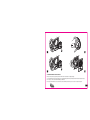
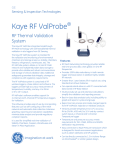
Thank you for purchasing the fan made by VENTS. iFAN is an innovative extract bathroom fan enclosed into a
compact casing. The unique technologies combined with smart electronics support the ideal comfort and
microclimate in your house. The stylish fan design matches well with any modern interior.
We do hope that you are happy with your fan's performance quality.
!
WARNING
Disconnect the fan from power mains prior to any connection, servicing and repair operations.
Mounting and maintenance are allowed for duly qualified electricians with valid electrical work permit for electric operations
at the units up to 1000 V after careful study of the present user's manual.
The single-phase power grid must comply with the acting local electrical norms and standards.
The fixed electrical wiring must be equipped with an automatic circuit breaker.
The fan must be connected to power mains through an automatic circuit breaker integrated into the fixed wiring system
with the gap between the breaker contacts on all poles not less than 3 mm.
Check the fan for any visible damages of the impeller and the casing before starting installation and set-up.
The casing internals must be free of any foreign objects which can damage the impeller blades.
Misuse of the device or any unauthorized modification is not allowed.
The fan is not to be used by children and persons with reduced physical, mental or sensory capacities, without proper
practical experience or expertise, unless they are controlled or instructed on the product operation by the person(s)
responsible for their safety.
Do not leave children unattended and do not let them play with the product.
Take steps to prevent ingress of smoke, carbon monoxide and other combustion products into the room through open
chimney flues or other fire-protection devices. Sufficient air supply must be provided for proper combustion and exhaust of
gases through the chimney of fuel burning equipment to prevent back drafting.
Transporting medium must not contain any dust or other solid impurities, sticky substances or fibrous materials.
Do not use the fan in the environment containing hazardous or explosive materials and vapours, i.e. spirits, gasoline,
insecticides, etc. Do not close or block the fan intake or extract vents in order to ensure the most effective air passage.
Do not sit on the fan and do not put objects on the fan.
Fulfill the requirements stated in this user's manual to ensure long service life of the product.
2
! WARNING
Recycle at the end of the service life.
Do not dispose the product with unsorted municipal trash.
Read the present user's manual carefully before proceeding with installation works.
Compliance with the manual requirements ensures reliable operation and long service life of the product.
Keep the user's manual available as long as you use the product. You may need to re-read the information on the
product servicing.
DELIVERY SET
The delivery set includes:
1. Fan - 1 pce;
2. Logo - 1 pce;
3. Remote controller - 1 pce;
4. Spigot Ø 100 mm - 1 pce;
5. Spigot Ø 125 mm - 1 pce;
6. Screws and dowels - 4 pcs;
7. User's manual - 1 pce.
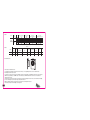
DESCRIPTION
Due to constant improvements the design of some models may slightly differ from that one described in this manual.
The product described herein is the axial fan made of high-quality plastic designed for extract ventilation of small and
medium-sized residential premises that are heated during winter period.
Table 1
Voltage [V]
Frequency [Hz]
Max. power [W]
Current [A]
RPM [min-1]
Max. air capacity [m3/h]
Ingress Protection
Weight [kg]
100-240
50-60
3,8
0,03
2200
133
IP 44
0,35
3
Table 2
Spigot
dia.
Model
100
iFan /
iFan Move
125
Speed
Max. air capacity
[m3/h]
24 Hours
Silent
Max
24 Hours
Silent
Max
Noise level at 3m
[dBA]
33
72
106
40
83
133
Air capacity,
factory settings [m3/h]
17
22
31
17
21
32
Air capacity
regulation range [m3/h]
33 ... 72
72 ... 106
40 ... 83
83 ... 133
33
72
82
40
83
97
Functions
Table 3
Model
Humidity
control
24 Hour
Turn-on
delay timer
Off-delay
timer
Speed
control
Interval
ventilation
External
switch
iFan
+
+
+
+
+
+
+
+
+
+
+
+
+
+
29 28
+
+
152
100/125
Overall dimensions
+
Pause
206
iFan Move
Motion
sensor
The fan has four ventilation modes:
1. Standby mode - standard operation mode for the fan in case of no signalling from the sensors or external switch.
In standby mode the fan does not run.
2. 24 Hours - the fan runs at low speed for minimum round-the-clock ventilation. As humidity level increases, the fan switches
to MAX mode (by default) or to SILENT mode. The fan switches to SILENT mode when the motion sensor is activated or
external switch is closed.
3. SILENT - silent operation mode of the fan. This mode is may be activated by the motion sensor, external switch or humidity
sensor. For humidity sensor, this mode may be activated from the fan.
4. MAX - humidity-activated operation mode. It is switched on as humidity level increases.
This mode is activated for the humidity sensor by default.
4
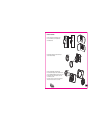
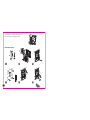
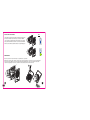
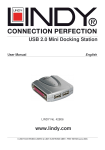
PRODUCT MOUNTING
The fan is designed for mounting into round
Ø 100 or 125 mm air duct or installation into
the ventilation shaft.
The replaceable adapter of required size may be
used to facilitate mounting.
100
125
The fan is equipped with a removable grille.
Press the latches slightly to release the grille from the
front cover. While installing the grille on the front cover
back match the latches and respective slots in the
cover and insert to click.
The pointer on the reverse side of the grille must be
directed to the shorter side close to the hole.
5
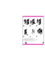
The fan casing has three round lowered tabs for cable entry.
Cut out a hole at the most suitable place with a knife.
FAN MOUNTING SEQUENCE
QF
6
1
2
3
4
5
6
7
8
9
10
11
12
The fan may be connected to power mains by four wiring diagrams.
The fan is compatible with 100-240 V / 50-60 Hz power mains.
The iFAN Move has Li terminal for connection to the lamp up to 200W/230 V or 100 W/120 V.
At this connection the fan will be switched on signal from the motion sensor.
7
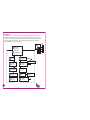
Wiring diagram 1
L and N terminals are connected to live and neutral respectively. The fan is always in standby mode and does not run.
As 24 HOURS Mode is activated the fan runs permanently at low speed to ensure minimum round-the-clock ventilation.
As motion sensor is activated (for iFAN Move only) the fan switches to SILENT mode. After no motion is detected the fan
reverts to standby mode. As humidity level increases the fan switches to MAX mode (by default) or to SILENT mode.
After humidity level drops the fan reverts to standby mode.
N L
N
L
LT
LI
Standby mode
(fan does not run)
or
24 Hours mode
3
(fan operated at 40/33 m /h)
Humidity
change
Turn-on delay
timer starts
(0-2-5 min)
MAX (SILENT)
mode is activated
8
Motion sensor
is activated
Turn-on delay
timer starts
(0-2-5 min)
Signal to LI terminal
(light is on)
Fan operation in
Silent mode
Humidity
stabilization
Motion
if off
Humidity extraction
timer starts
(30-45-60 min)
Turn-off delay
timer starts
(5-15-30 min)
Signal to LI terminal
(light is off)
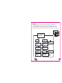
Wiring diagram 2
L and N terminals are connected to live and neutral respectively and L and LT terminals are joined by the jumper.
The fan is always in SILENT mode. 24 Hours mode may not be activated. No matter of the signal from the motion sensor
the fan operated in SILENT mode. As humidity level increases the fan switches to MAX mode (by default) or continues
operation in SILENT mode (if adjusted by the user). After humidity level drops to standard level the fan reverts to SILENT mode.
N L
N
L
LT
LI
Fan operates at air flow:
3
83/72 m /h (MAX)
40/33 m3/h (MAX)
Humidity
change
Turn-on delay
timer starts
(0-2-5 min)
MAX (SILENT)
mode is activated
Motion sensor
is activated
Turn-on delay
timer starts
(0-2-5 min)
Signal to LI terminal
(light is on)
Fan operation in
Silent mode
Humidity
stabilization
Motion
if off
Humidity extraction
timer starts
(30-45-60 min)
Turn-off delay
timer starts
(5-15-30 min)
Signal to LI terminal
(light is off)
9
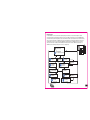
Wiring diagram 3
L and N terminals are connected to live and neutral respectively. LT contact is connected to live through external switch,
light switch. The fan is always in standby mode. As 24 HOURS Mode is activated the fan runs permanently at low speed to
ensure minimum round-the-clock ventilation. As the external switch is closed the fan switches to SILENT mode.
After the external switch is off the fan reverts to standby mode. As motion sensor is activated (for iFAN Move only) the fan
switches to SILENT mode. After no motion is detected the fan reverts to standby mode. As humidity level increases the fan
switches to MAX mode (by default) or to SILENT mode. After humidity level drops the fan reverts to standby mode.
N L
Standby mode
(fan does not run)
or
24 Hours mode
(Fan operates at 40-33 m3/h)
Humidity
change
Switch is
closed
MAX (SILENT)
mode is activated
Humidity extraction
timer starts
(30-45-60 min)
10
Motion sensor
is activated
Turn-on delay
timer starts
(0-2-5 min)
Turn-on delay
timer starts
(0-2-5 min)
Humidity
stabilization
N
L
LT
LI
Fan operation in
Silent mode
Switch
is off
Motion
if off
Turn-off delay
timer starts
(5-15-30 min)
Signal to LI terminal
(light is on)
Switch
is off
Signal to LI terminal
(light is off)
S
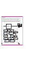
Wiring diagram 4
L and N terminals are connected to live and neutral respectively. LT terminal is connected to live through the external
momentary switch that is activated by opening a door. The fan is in standby mode and does not run. As 24 HOURS Mode is
activated the fan runs permanently at low speed to ensure minimum round-the-clock ventilation. As the external momentary
switch is closed the fan switches to SILENT mode for the period adjusted in the off-delay timer. After that the fan reverts to
standby mode. As motion sensor is activated (for iFAN Move only) the fan switches to SILENT mode. After no motion is
detected the fan reverts to standby mode. As humidity level increases the fan switches to MAX mode (by default) or to
SILENT mode. After humidity level drops the fan reverts to standby mode.
N L
Standby mode
(fan does not run)
or
24 Hours mode
3
(Fan operates at 40-33 m /h)
Humidity
change
External switch
is activated
Turn-on delay
timer starts
(0-2-5 min)
MAX (SILENT)
mode is activated
Humidity
stabilization
Humidity extraction
timer starts
(30-45-60 min)
N
L
LT
LI
Sk
Motion sensor
is activated
Turn-on delay
timer starts
(0-2-5 min)
Signal to LI terminal
(light is on)
Fan operation in
Silent mode
Motion
if off
Signal to LI terminal
(light is off)
Turn-off delay
timer starts
(5-15-30 min)
11
FAN ADJUSTMENTS
The fan is adjusted at the factory and is ready for operation. It is a fully operable product without extra adjustments.
However if you want to adjust the fan according to your needs, please follow the instruction below.
You can always reset to the factory settings.
Factory setting parameters (spigot 125/spigot 100):
- speed in standby mode - 0 m3/h
- speed in 24 Hours mode - 40/33 m3/h
3
- speed in Silent mode - 83/72 m /h
3
- speed in Max mode - 97/82 m /h
- humidity extraction Max mode
- turn-on delay time - 0 min
- off-delay time - 5 min
- humidity extraction time - 30 min
- motion sensor (for iFan Move) is included.
FAN OPERATION INDICATION
The fan is turned on by the motion sensor or external switch - the light indicator STATUS is green.
The fan is in standby mode - the light indicator STATUS blinks green once in 2 seconds.
Fan operation in 24 Hours mode - the light indicator is red.
Fan operation in humidity extraction mode - the light indicator STATUS blinks red once in 2 seconds.
Fan operation in interval ventilation mode - the light indicator STATUS blinks in turn red and green once in 2 second.
Fan operation in turn-on delay mode - the light indicator STATUS blinks red twice in 1 second.
12
You can adjust the fan both with the control panel located on the fan or with the remote controller. The remote controller has
3 m effective range. To attain the maximum effective range response direct the remote controller straight to the fan.
ATTENTION! The fan covers of Melange, Ruby Star, Champagne, Silver colours provide high signal conductivity from the
remote controller and do not influence the signal transferability. The covers of Graphite, Violet Topaz or Black Sapphire may
suppress the signals. To avoid this, please remove the front cover during adjustment operations.
After each signal reception the fan sends an acoustic signal to confirm the setting adjustment. In case of no acoustic signal
from the fan try to press a button on the controller once again or come nearer to the fan.
11RC buttons are not available on the remote controller (available for the model iFan Celsius).
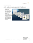
Control panel
Remote controller
iFan
1RC
2RC
5RC
SILENT
iFan Move
7CP
6CP
5CP
4CP
3CP
2CP
1CP
4RC
6RC
ON/OFF
MOVE
MAX
3RC
PAUSE
7RC
8RC
TIMER SETTINGS
9RC
10RT
ON/OFF
24 H
11RC
TEMPERATURE SETTINGS
13
SILENT MODE SPEED ADJUSTMENT
By default the speed is 83/72 m3/h.
To set the speed:
Press the buttons "3CP" and "4CP" on the control panel.
Press the buttons "4RC" on the remote controller.
Press the buttons "3CP", "4CP" or "4RC" once to display the
current air capacity.
MAX MODE SPEED ADJUSTMENT
By default the speed is 97/82 m3/h.
To set the speed:
Press and hold the button "7CP" and then press the buttons "3CP" and "4CP"
on the control panel.
Press the buttons "5RC" on the remote controller.
To display the current air capacity on the control panel, press and hold the
button "7CP" and then press the button "3CP" or "4CP" once.
To display the current air capacity on the remote controller, press the
buttons "5RC".
Number of active
light indicators
1
2
3
4
5
6
7
8
9
10
Number of active
light indicators
1
2
3
4
5
6
7
8
9
10
Air capacity,
[m3/h]
40/33
44/37
48/41
52/45
57/49
62/53
67/57
72/61
77/66
83/72
Air capacity,
[m3/h]
83/72
87/75
92/79
97/82
103/86
109/90
115/94
121/98
127/102
133/106
HUMIDITY EXTRACTION MODE SELECTION
By default the extraction mode is MAX mode:
To select the humidity extraction mode:
Press the button "1CP" on the control panel in cycles.
Press the button "2RC" (for Silent) or "3RC" (for Max) on the remote controller.
Max - active humidity response mode with the best impeller performance.
Silent - active humidity response mode with silent operation.
Press the button "Humidity mode" once to display the current mode.
14
SILENT
MAX
HUMIDITY EXTRACTION MODE ADJUSTMENT
The default time is 30 minutes.
After crossing the humidity set point the fan switches to higher
speed to extract excessive humidity. After the humidity level
stabilization the timer is activated and the fan runs for the set
time period to enable total extraction of the excessive humidity
and then it reverts to the previous operation mode.
If humidity rises less than by 20% for 10 minutes, the timer
countdown is 15 minutes.
Stabilization of humidity is understood as humidity change
no more than by 3% within 5 minutes.
To adjust the humidity extraction timer:
Press and hold the button "7CP" and press the button "2CP"
in cycles on th control panel.
This adjustment is not available from the remote controller.
Press and hold the button "7CP" and press the button "2CP"
on the control panel once to display the current settings of the
humidity sensor timer.
30 minutes
45 minutes
60 minutes
5 minutes
15 minutes
30 minutes
OFF-DELAY TIMER ADJUSTMENT
The default time is 5 minutes.
When the motion sensor is activated or the external switch is closed,
the fan operates for some time and then reverts to standby mode.
This time is adjustable.
To adjust the timer:
Press the button "2CP" in cycles on the control panel.
Press the buttons "9RC" (5, 15 or 30 respectively) on the remote
controller.
Press the button "2CP" on the control panel once to display the
current off-delay timer setting.
15
TURN-ON DELAY TIMER ADJUSTMENT
The default time is 0 minutes.
If you have to visit the bathroom often, you can adjust the turn-on
delay timer to avoid the fan unnecessary switching.
After humidity increases or after signal from the external
switch/motion sensor, the fan switches to higher speed not
immediately, but in some time period.
To adjust the turn-on delay timer:
Press and hold the button "5CP" and press the button "2CP" in
cycles on the control panel.
Press the buttons "8RC" (0, 2 or 5 respectively) on the remote
controller.
Press and hold the button "5CP" on the control panel and then
press the button "2CP" once to display the current on-delay timer
setting.
SWITCHING MOTION SENSOR
(FOR IFAN MOVE MODEL)
The motion sensor is off by default.
The light indicator "Status" under the button glows when the motion
sensor is turned on.
To turn the motion sensor on:
press the button "5CP" on the control panel.
press the button "6RC" on the remote controller.
Press the button "5CP" once to display the current setting.
16
0 minutes
2 minutes
5 minutes
ACTIVATION 24 HOURS MODE
In this mode the fan has minimum air capacity before the humidity sensor,
motion sensor or external switch is activated.
To activate 24 HOURS mode:
Press the button "6CP" on the control panel.
Press the button "10RC" on the remote controller.
This function is not available for the wiring diagram 2.
EXTRA FUNCTION - PAUSE
This function is controlled from the remote controller only.
In you do not want to feel disturbed by the fan operation, you may stop it for 45 minutes by pressing the button "7RC" on the
remote controller. The fan reverts to the previous operation mode after the timer countdown or in case of pressing the button
"7RC" once again.
EXTRA FUNCTION - SWITCHING FAN ON/OFF
This function may be controlled from the remote controller only.
If the fan is switched off with the button "1RC" on the control panel, the light indicator on the fan goes off and the fan
does not response to any external functions (temperature or humidity fluctuations, motion registration or activation by the
external switch). The interval ventilation function remains activated and in 15 hours the fan switches on to ventilate a premise
for 2 hours.
EXTRA MODE - INTERVAL VENTILATION
Automatic function.
It can not be adjusted or turned off.
3
After 15 hours standstill the fan is switched on for 2 hours to ventilate the room with air capacity 72 m /h.
If the fan receives a signal from a sensor during interval ventilation operation, it switches to the mode according to the
activated sensor.
17
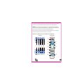
RESET TO FACTORY SETTINGS
Push
The fan side panel incorporates a built-in manual power slide switch.
Turn the fan off with this power switch, press the button "MODE"
on the control panel, hold this button and switch the fan on with this
slide power switch. When the fan turns on, hold the button "MODE"
within 5 seconds until the light under the button stops blinking green.
MAINTENANCE
Disconnect the fan from power mains prior to any maintenance operations!
Maintenance means periodic clearing of the fan surfaces from dust and dirt. To clean the fan use a soft cloth wetted in a
water-soap solution. Wipe the surfaces dry after washing. Avoid liquid splashes on the motor and the circuit board!
The power supply battery in the remote controller must be regularly replaced, model CR2025 3V.
1
18
2
3
4
5
6
STORAGE AND TRANSPORTATION RULES
Transport the product by any transportation vehicle in the manufacturer's original package.
Store the delivered product in the manufacturer's original packing box in a dry ventilated premise with the temperature range
from +50C up to + 400C and relative humidity less than 80%.
The storage environment must not contain dust, acid or alkali vapours that may cause corrosion of the product parts.
19
OPERATION RULES
The fan is designed for connection to single-phase ac 100-240 V / 50-60 Hz power mains.
The fan is designed for continuous operation always connected to power mains.
The fan is rated for operation at the ambient temperature ranging from +1°C to +45°C.
The fan is double-insulated and requires no grounding.
The fan complies with the requirements according to the EU norms and directives, to the relevant EU-Low Voltage Equipment
Directives, EU-Directives on Electromagnetic Compatibility.
MANUFACTURER'S WARRANTY
The fan is manufactured at the factory of "Ventilation systems" PrJSC (hereinafter referred to as the Manufacturer).
By purchasing this product the customer confirms to have read and agreed to the terms, rules and requirements related to
operation, storage, transportation, mounting, adjustment, connection, maintenance and repair as well as warranty obligations
with respect to this product as set forth in the manufacturer's accompanying documentation to the product.
The manufacturing company sets forth the warranty period (service life) of the product as 60 months following the sale date via
retail network subject to the customer's ensuring compliance with the rules of transportation, storage, mounting and operation
of the product. In case of any malfunction of the product through the fault of the Manufacturing company within the warranty
period (service life), the customer shall have the right to elimination of the manufacturing defects by means of warranty servicing
performed free of charge. The warranty servicing implies performance of activities related to elimination of defects in the product
aimed to provide intended use of the product by the customer. The defects are eliminated either by replacing or repairing such
a product or a part (component) thereof.
NOTE: with the purpose of performing warranty servicing you please produce User Manual or other relevant substituting
document and the payment document as an evidence of the purchase with indication of the sale date. The product model shall
comply with that one specified in the User Manual or other relevant substituting document. With the purpose of performing
warranty servicing please contact the trade company where you purchased the product. If warranty servicing on the spot proves
impossible, you will be provided with the necessary information regarding rendering of this service.
Manufacturer's warranty shall not apply in the following cases:
- in case the customer fails to provide the product in complete according to the package contents specified in the User Manual or
other relevant substituting document, including any components disassembled by the customer;
- in case of incompliance of the model or marking of the product with data specified on the product packaging and in the User
Manual or other relevant substituting document;
20
- in case of non-timely technical maintenance of the product by the customer (dust, mud, oil condensate, foreign particles);
- in case of causing external damage to the product by the customer ('damage' shall not apply to external changes of the product
required for the product mounting);
- in case of altering the product design or further reworking of the product;
- in case of replacing and using parts, units and components of the product not prescribed by the manufacturing company;
- in case of other use of the product other than intended use;
- in case of the customer's violating product operation rules;
- in case of connecting the product to electric mains of voltage exceeding voltage value specified in the User Manual;
- in case of step voltage that resulted in the product failure;
- in case of the customer's performing unauthorised repair of the product;
- in case of performing repair of the product by third persons unauthorized by the manufacturing company;
- in case of warranty period (service life) expiry;
- in case of the customer's violating transportation rules assuring prevention of damaging and/or destruction of the product;
- in case of the customer's violating product storage rules;
- in case of performing unlawful actions by third persons with respect to the product;
- in case of force majeure (fire, flood, earthquake, war, hostilities of any kind, blockade);
- in case of absent seals, provided such seals are prescribed by the User Manual or other relevant substituting document;
- in case of unavailable warranty card;
- in case of unavailable payment document to confirm the purchase with indication of the sale date.
The manufacturing company shall be responsible for defects arising through its fault prior to the moment of transferring the
product to the ownership of the customer. The manufacturing company shall not be responsible for defects arising after
transferring the product to the customer and caused by the customer's violating the rules of transportation, storage, assembly
and operation of the product, or by actions of third persons, an accident or force majeure circumstances.
The manufacturing company shall not be responsible for damage to health and property of the customer caused by the
customer's violating the User Manual or other relevant substituting document; other use of the product by the customer other
than its intended use, or by failure of the customer to comply with warnings and other information on the product specified in the
User Manual or other relevant substituting document, or by the customer's violating the rules of transportation, storage, mounting,
maintenance and operation of the product.
21
22
23