1
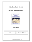
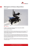
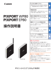
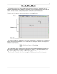
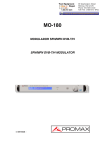
Foam Casualty NCGen User Manual, Rev. 4
Table of contents
1.0 Introduction
2.0 Definitions
3.0 Installation
4.0 Generation
4.1 Lines
4.2 Face(s)
4.3 Face to Pocket
4.4 Surfaces
4.5 Wire Tool Introduction
4.6 Wire Tool Path Construction
4.7 Roughing Passes
5.0 Playback
6.0 Options
6.1 Cut Order
6.2 Basic Options
6.3 Post Processor
7.0 Machine Setup
8.0 Advanced Configuration
8.1 Adjusting the Axis Names for a Custom Hot Wire CNC Machine
8.2 Adjusting the Tower Distance and Offset for a Custom Hot Wire CNC Machine
9.0 Sample G-code File
10.0 Online Reference
1.0 Introduction
NCGen is a powerful SketchUp extension that facilitates generation of 3 and 4 axis G-code for use with
milling and hot wire style CNC machines. NCGen has the capability to generate 2D/2.5D/3D mill tool
paths and tapered hot wire tool paths. The design philosophy is such that if you can draw a line in
SketchUp, NCGen has the ability to export that line directly as a cut path for your CNC machine. This is
done by simply controlling the Layer name that lines are drawn on, making those lines into a Group,
placing that group on a named Layer, and then giving that group a unique name. While that may be a lot
to think about, this means that NCGen only uses native SketchUp functions to look for and export tool paths
as G-code. Furthermore, it is a relatively simple task to write methods that will automatically make use of
these native functions. If an automated task should ever fail, standard SketchUp functions can always be
used to correct or work around the problem.
Return to Table of Contents - Foam Casualty NCGen User Manual – Rev. 4
Page 1 of 20
2.0 Definitions
G-code – Numeric Code that defines the motion of the CNC machine.
Edge – Edges in SketchUp are simply lines.
Face – Faces are formed in SketchUp when at least 3 edges are plainer.
Layer – Layers in SketchUp are used for organization and controlling visibility of objects.
Group – Collections of objects in SketchUp that are isolated from interacting automatically with other
objects.
Component – Similar to groups, however components are used for multiple like objects. If a change to one
component is made, all components will be altered.
The Origin – This is the zero location for both model space and G-code. In the model space this is where
the red, blue, and green lines intersect. Positive space is considered the solid side of the colored lines.
3.0 Installation
NCGen is an extension for the popular CAD program SketchUp. It is compatible with both the free and
pro versions. NCGen requires SketchUp 2014 or later versions to run. NCGen is distributed as an rbz file.
An rbz file is really only a zip file that has it's extension renamed. Download and note the location of the
rbz file, NCGen_XXXX.rbz. SketchUp has a built in feature that allows you to install rbz extensions by
simply browsing for the file. To install NCGen all you need to do is to load SketchUp and go to the top
and click Window, Preferences, select Extensions in the choices on the left, then click "Install Extension..."
Select the “rbz” file and NCGen will then be installed properly.
NCGen automatically creates a folder in your home folder called called 'NCGen'
NCGen automatically creates a folder structure (eg. \NCGen\post) in your home directory to allow for
easier manual editing of the post processor, however it is no longer necessary to edit this file by hand as all
options are included in the Order Menus.
As of January 2015, NCGen will automatically check the page http://foamcasualty.com/ncgen-version to
determine if it is up to date. If it finds an update, it will open a new web page that will allow you to
manually download and update the extension.
Return to Table of Contents - Foam Casualty NCGen User Manual – Rev. 4
Page 2 of 20
4.0 Generation
NCGen works by exporting G-code from lines found in the model that are drawn with the correct criteria.
Positioning:
G-code is exported by the absolute position of the lines found in the model.
The Origin (zero) in the model space will be the absolute g90 zero on the physical machine.
NCGen does not support g91 incremental positioning at this time.
Sequential Lines:
All lines drawn will need to make sense from the perspective that the machine
should have a clear sequential path to follow. For instance, drawing two lines
that intersect is not going to be possible for a machine to cut without the
added instruction of what the machine should do once it reaches the
intersection and what it should do once it reaches the end of the first line.
NCGen has overcome this issue to some extent, however this situation should
be avoided if possible, as it will not be possible for NCGen to figure out the
intent of ALL lines in the SketchUp model space.
Rather than scripting for every
possible scenario, these issues are
more appropriately overcome by
the user breaking the lines up into
separate logical paths. One
method is simply to route the lines
in a manner that the machine will
understand. For instance in the
figure to the right lines are drawn
to avoid making intersections and
can be logically followed.
Another way to overcome this problem is by grouping the two lines
separately so that they can be connected automatically by a g0 rapid
travel path. In the picture to the right the two lines actually intersect,
however each line is in a separate Group allowing for the separation of
two separate lines. NCGen will create a rapid g0 between these two
lines based on their cut order and the intent of the travel path is clear.
Automatic Generation:
It would be incredibly tedious to need to draw every single point in a G-code file by drawing lines,
assigning them a Layer, make the lines into a Group, then ensuring the Group is on the correct Layer, and
then ensuring a unique group name. With these fundamentals in place however, we have facilitated
several methods to assist in automating the process, and if these automated methods should ever fail, the
user will always have the ability to correct the problem manually using native SketchUp functions, allowing
the project to be moved along without waiting for an update to fix or work around the underlying issue.
Return to Table of Contents - Foam Casualty NCGen User Manual – Rev. 4
Page 3 of 20
4.1 Lines
G1 Path Generator Tool
This tool works on groups of both edgse and faces.
Direct Tool Paths from Edges:
To create tool paths for engravings or single line lettering,
simply draw lines. Lines may be 2d or 3d, they may form a
closed loop, and may even self intersect provided at least
one of the self intersecting lines is straight through the other.
Lines to a Group.
Lines must be made into a Group. A Group can be made by
right clicking on the selection you intend to make into a
Group and then selecting “Make Group” from the context
menu. (Hint: try triple clicking and also assigning a hot key
to the make group command).
Make a Tool Path:
Click the G1 Path Generator Icon and click on the desired Group. The extension
will automatically assign the start of the line by the point closest to The Origin or to
the highest of the two end points of your Group of lines. Once NCGen determines
the start point it will assign a lead in line that is currently a predefined direct plunge
cut based on the Material Thickness Plane parameter. It will then assign the correct layers to both the lines
and to the Group, and ensures a unique name. If successful it will store the cut path into the Order Menu
so that the order of cuts may be adjusted later.
The tool will prompt the user to Name of the Cut Path / Part.
If the Group had a name prior to selecting it with the G1
Path Generator Tool, the name will automatically be
inherited from the Entity Info, and no prompt will be given.
The direction of cut is represented by color. The darkest
edges are the first to be cut. Hint: Lines that are generated
by NCGen are colored coded for reference, but this option
must be turned on to make SketchUp display the color (In the
SketchUp menu bar, go to Window, then Styles, then Edit,
and then select Color: By Material).
The G1 Path Generator Tool uses one modifier when converting lines directly into cut paths:
Ctrl – Press once to reverse the starting point of the line.
Return to Table of Contents - Foam Casualty NCGen User Manual – Rev. 4
Page 4 of 20
4.2 Face(s)
Offset Tool Paths from Faces:
G1 Path Generator Tool can also create an automatically offset 2D cut path from a single grouped face.
These paths are created by drawing and selecting a single face and then making it into a Group. The G1
Path Generator Tool will then create an offset to the inside or outside of the selected grouped face. The
offset distance is controlled by the currently set bit diameter option found in the Basic Options tab of the
Order menu. This tool also has the option to automatically create 'tabs' to keep the part attached to the
stock so that it is unlikely to move during the milling process.
It is very important to select only a single face to
produce an offset.
Note the set of pictures to the right are showing a
face vs a surface and although both shapes look to
be planer, they may not be. A face with hidden
geometry will most likely produce undesired results.
SketchUp sometimes automatically hides or softens
lines to produce better looking models. Models in
SketchUp are defined only by surfaces, which are
simply combined faces, which are simple collections
of lines. Typically surface modeling programs like
SketchUp use the basic shape of a triangle to define a face, but SketchUp will also create a face onto any
set of points that are exactly on the same plane and are all connected by lines.
If the points are not on the same plane SketchUp
may try to fool you by automatically creating
hidden geometry as in the above figure. The G1
Path Generator Tool will not work to produce an
offset with such hidden geometry. It will work with
any polygon actually defined as a face, so long
as all the points are on a plane in space as
SketchUp requires. If the selected face is not
square to the XY plane, NCGen will make an
offset so that it is square to the XY plane, although
it will not preserve the length of the original
angled geometry, the offset simply ignores any Z
values.
The figure to the right shows how to enable
Hidden Geometry and the result is the dashed line
shown through the rectangle. To use this shape
the hidden geometry must be deleted and the
remaining points must be made planer.
Return to Table of Contents - Foam Casualty NCGen User Manual – Rev. 4
Page 5 of 20
Face to a Group:
To create an offset tool path create a single face, make it a Group, and then use the G1 Path Generator
tool to select it. Nested groups are not allowed by this tool.
If the group was named, the name will be inherited, otherwise the user will be prompted for a name.
Offset Determination:
NCGen will automatically offset the face and create additional cut paths as necessary if the resulting offset
creates an undercut. Offset distance is dependent on the bit diameter option currently set in the Order
Menu under the Basic Options tab. All cut paths will have the point closest to The Origin defined as the
start point and it will automatically create a plunge style lead in based on the Material Thickness Plane
parameter.
Color denotes the direction of cut, dark to light. For outside offsets the direction should be clockwise. For
inside offsets the direction is reversed or counter-clockwise.
Multiple Step-down passes:
The G1 Path Generator Tool now features a step down cut feature for 2d milling. This feature compares the
currently set Material Thickness Plane and the height of the actual cut to the Pass / Step-down Amount. If
multiples of the Pass / Step-down Amount will fit within the Material Thickness Plane, additional passes will
be created based on the currently set values in the Order Menu, under the Basic Options tab.
The G1 Path Generator Tool uses the following modifiers when dealing with a grouped face:
Ctrl – Press once to makes internal offsets and reverse the order of the cut path.
Shift – Press once to turn off tabs.
Return to Table of Contents - Foam Casualty NCGen User Manual – Rev. 4
Page 6 of 20
4.3 Face to Pocket
Pocket Generator
NCGen supports simple pocket
milling as defined by a single parallel
to the red-green axis grouped face.
The Pocket Generator creates a
repetitive offset of the outside edge of
any single grouped face towards the
center of the face. The initial offset
will contain the full detail of the edges
around the outside defining loop of
that face. Subsequent offsets will
simplify the edges to help speed both
the generation time and the time it takes for the actual mill to follow the path. The last offset generated on
each pass will always be where the start of the cut is, and this usually this will be at the center of the face.
The offset distance is controlled by the currently set bit diameter option found in the Basic Options tab of
the Order menu. The cuts should follow a clockwise direction for conventional milling.
The Pocket Generator will prompt the
user for some information.
Total Pocket Depth is the overall depth
of the pocket in inches from the selected
grouped face. This distance will always
be down in the dotted blue axis
direction (-Z Axis).
Max Material to Remove Per Pass is the
maximum amount of material to mill in
inches for each pass of the pocket. This
number may be rounded downward so
that an even number of passes will be
made to obtain the Total Pocket Depth.
A plunge style lead in from the Material Thickness Plane will be drawn to the selected face, followed by a
ramp in path to the last offset path created (towards the center of the pocket).
The Pocket Generator tool will only create flat 2d pockets at this time. A sloped pocket is not yet possible
due to the complexities in generating these types of offsets. In the event that two or more offsets are
created from the shape of the face, this tool will attempt to automatically connect these offsets with a joining
mill path line, this line may not be optimal and the original face may need to be broken up into several
grouped faces to overcome this issues.
Return to Table of Contents - Foam Casualty NCGen User Manual – Rev. 4
Page 7 of 20
4.4 Surfaces
Generate 3D Tool Path
3D tool path generation is provided to create a tool path from
a surface model. This tool creates a path from intersections in
a 3d surface at a user adjustable Step-Over distance by one
of three methods.
Offset: Accounts for the currently set bit diameter by offset, but
only in the green-blue direction.
Scale: Approximates the currently set bit diameter by scaling
the original surface in the correct directions.
Direct: Applies intersection lines directly to the face of the
original surface with no compensation.
The tool will also create a second clockwise path known as Pencil Mill Path that follows the lowest points of
each intersection. This allows the milled part to have a clean edge around the intended surface.
Additionally there is an option to Cut Other Side for the scale and offset methods, this option might be used
if milling a depression of small pocket with complex geometry.
The selected surface model must be defined in the
following manner:
The surface must be open on the bottom. The tool
path will be generated by finding the intersection at
each step-over. If the found intersection creates a
loop with no bottom opening the resulting tool path
would mill out the entirety of the intended surface
and therefore is not permitted.
The surface must be a Group, and my not have
nested Components.
This tool can be finicky, however most problems are
due to the original surface model. Generally, the simpler the surface model, the more effective this tool will
be. Please note, this portion of NCGen is still under heavy development and is likely to change often as
NCGen progresses. This process is also highly processor intensive and it may take some time to create a
complex tool path for large parts or for very precise tool paths which will require a great multitude of
intersections and offsets. It is normal for the computer to appear to freeze up once a complex surface is
clicked, please remember to save before using this tool and before attempting to export G-code from such
complex models.
There are some limitations in generating 3D tool paths in this manner. While we explore different options to
make all surfaces possible to mill, faster results will be obtained by simply breaking the surface of the part
up into multiple areas to be milled at different stages in the operation.
Return to Table of Contents - Foam Casualty NCGen User Manual – Rev. 4
Page 8 of 20
4.5 Wire Tool Introduction
Generate Hot Wire Tool Path
The hot wire tool can be confusing to use at first. These are some basic principles of usage to keep in mind
when using that may prove helpful.
1. Zero in the model is zero on the machine. For FC6A users remember NCGen assumes by default that
the user will be using a mill in conjunction with the hot wire, NCGen is set up to use the given origin in
SketchUp as the actual zero point of the physical machine for the cutting operation (the location both the
mill and wire are touched off / referenced to). (NOTE: This is not to be confused with the HOME
LOCATION of the physical machine, the home location is usually an entirely different location then the zero
point for milling / wire operations. Both of these locations can of course be completely redefined, however
if you decide to do this you should know what you are doing and why). For consistency, and to minimize
human error, we have found it best to ALWAYS touch off the mill and the wire of the physical machine to the
front left corner of the work surface, and this in turn will directly relate back to SketchUp as the origin point.
See Section 8.0, Machine Setup, for more information.
2. The hot wire uses planes parallel to the green
and blue axis for the primary YZ tower and
secondary VW tower. The YZ tower will control
the speed of the wire travel, and is traditionally
on the left/front side of the machine, the side
closest to the origin.
3. The secondary tower known as the VW tower
will be located further to the right/back of the
machine. The speed the VW tower will travel at,
is dependent on the speed of the YZ tower, as
both sets of coordinates are on the same G-code
line (ie: 'g1f4 y1.0 z1.0 v2.1 w3.1')
4. The YZ and VW tool paths MUST have exactly the same number of edges for both towers. It is not
possible to have 5 edges for the YZ and 10 for the VW, and NCGen will not be capable of determining
where the extra edges should be added, nor will it be able to remove extra edges with desired results.
5. NCGen does not currently feature cutter compensation, so please understand you are drawing the direct
cut paths for the wire.
Return to Table of Contents - Foam Casualty NCGen User Manual – Rev. 4
Page 9 of 20
4.6 Wire Tool Path Construction
Draw the two tool paths and make them each a group:
1. A tool path at each end of the Stock will need to be drawn by the user on the green-blue plane.
2. Tool paths must include a Lead-in / Lead-out for the wire to travel along (this can be the same line).
3. The tool paths must have the same number of lines.
4. The two tool paths must be made into two separate groups.
Use the Generate Hot Wire Tool Path tool:
1. Click Generate Hot Wire Tool Path icon.
2. First click the tool path group drawn closest to The Origin (for the YZ tower).
3. Second click the tool path further from The Origin (for the VW tower).
4. Name the wire path (unless the group already has a name).
5. NCGen will automatically generate projected paths to be exported as green and red lines.
The direction of cut is displayed
as color, dark to light.
A tapered cut can be obtained
by scaling one of the two tool
paths, but remember to make
the larger of the two tool paths
towards the side of the YZ
tower as it will be referencing
that side for the set speed of
travel.
Sometimes tapered cuts can
produce odd looking results.
We recommend using the Load
Machine NC Code into Model
tool to confirm the function of the exported code before committing any real stock on the machine. See the
Playback Section.
Additionally NCGen does not check the extents of the automatically projected created paths. The user will
need to be sure that the results of the user drawn shape are contained in the physical limits of the intended
CNC machine.
Return to Table of Contents - Foam Casualty NCGen User Manual – Rev. 4
Page 10 of 20
4.7 Roughing Passes
Generate Roughing Planes
This tool is used to generate roughing passes for the surface model you intend to cut. The way this tool
works is by creating intersections with the surface model in the blue Z direction and then at those
intersections creating repeating offset paths to a defined oversized bounding box to be milled successively.
This tool should create cut paths from the outside of the material towards the part. Again the larger the part
or shallower the roughing passes the longer it will take to generate these paths. It is normal for the
computer to appear to freeze up once a complex surface is clicked, remember to save before using this
tool. This tool is also under heavy development and may produce buggy results at this time.
Return to Table of Contents - Foam Casualty NCGen User Manual – Rev. 4
Page 11 of 20
5.0 Playback
Load Machine NC Code into Model
Loads G-code tool paths into the current model with a delay so that you can see the path. This reads the Gcode directly, what you've exported is what it loads. This tool is meant to be used as a preview feature for
4 axis hot wire G-code but is being developed to load basic G-code as well.
This tool will estimate how long it will take to demonstrate the file and will automatically attempt to shorten
the time if it estimates the process taking longer then two minutes.
Occasionally on large tool paths the screen will freeze up when this tool is used. While this is not desired,
the tool will provide the option to play the file again. Normally the second time will show the entire cut no
matter the size of the file.
Return to Table of Contents - Foam Casualty NCGen User Manual – Rev. 4
Page 12 of 20
6.0 Options
It should be noted that NCGen will only automatically generate lines based on the current settings in the
Order Manager. Lines automatically generated will not change based on these settings.
Order Menu
6.1 Cut Order
The cut order is a list of cut paths found in the Sketchup Model space. They are displayed as sequential
cuts and will be exported in this same manner. Cuts can be selected in the list by left clicking on them.
When selected in the list, the cut will select in the model space.
Cuts can also be renamed by double clicking the listed item.
Wire paths have three special buttons:
Reverse Left reverses the cut order of the YZ tower projection. The
color in the model space will reflect the change in direction.
Reverse Right reverses the cut order of the VW tower projection.
The color in the model space will reflect the change in direction.
Reverse Both reverses the cut order of both the YZ and VW tower
projections. The color in the model space will reflect the change in
direction.
The following functions apply to all listed paths:
Move up moves the selected item up the cut order list
Move down moves the selected item down the cut order list
Delete Cut deletes the selected cut path from the list and
the SketchUp Model space.
Draw G0 draws (in red) the rapid tool paths for your reference
Export NC Code exports a G-code file in the order as listed.
Return to Table of Contents - Foam Casualty NCGen User Manual – Rev. 4
Page 13 of 20
6.2 Basic Options
Bit Diameter: in inches which controls offset amounts and spacing.
Spindle Speed: in rotations per minute for the m3s* command.
Mill Cutting Feed: feed rate the mill will cut, in inches per minute.
Mill Plunge Feed: the rate the mill will plunge, in inches per minute.
Hot Wire Feed Rate: the hot wire feed rate, in inches per minute.
Hot Wire Temperature Rate: the hot wire percent demand relating to
temperature of 0 to 100%.
Clearance Height Plane: the absolute distance in inches above the
Zero Plane to where it is safe to freely move the tooling. For instance if
working with 2 inch thick stock, a clearance height of 2.125 is
appropriate. This corresponds to g0 rapid travel height.
Material Thickness Plane: the absolute distance in inches above the
Zero Plane to where material is expected to be machined. This is the
plane to which lead-in cuts will start from.
Pass / Step-down Amount: in inches of the maximum amount of
material to remove on a milling pass.
The following options are for playback:
Preview Speed control: allows two methods to play back G-code for wire cuts:
Timed Playback Method: smooth playback, after the set delay draw the next line.
Skip Line Playback Method: choppy playback, instantly draws lines a group at a time, best for large files.
Timed Playback Speed: Playback delay of 0.001 Seconds, 0.01 Seconds, 0.1 Seconds, or 1 Second.
Skipped lines during playback: The number of lines to draw at a time during playback.
Apply: Sets the current options for the SketchUp session.
Defaults: Loads the default options that are hard coded into NCGen.
Save to File: Sets the current options and saves them to file.
Return to Table of Contents - Foam Casualty NCGen User Manual – Rev. 4
Page 14 of 20
6.3 Post Processor
There are many options that can be configured in the Post Processor tab.
Hot Wire Rate Command: String to use to set the Hot Wire
Temperature Rate from the Basic Options Tab.
Hot Wire On Command: String to use to turn on the wire.
Hot Wire Off Command: String to use to turn off the wire.
Space Between Towers: Please see the next section.
Tower Offset: Please see the next section.
G64/G61 Mode: G61.1, G61, or G64 Path Travel Modes.
G64 Tolerance: Tolerance for G64 Path Mode, if G64 is used.
Reference: LinuxCNC G-Code Reference
Wire Mode: Tool Change request for calling the wire.
Mill Mode: Tool Change request for calling the mill.
End Routine: Routine request for the end of the file.
Hide Tool Changes: Implements an (Axis HIDDEN) feature for better
previews when using LinuxCNC.
Insert G20/G21 Imperial/Metric Call: If checked g20 is inserted if
the model units are in inches and g21 if model units are set to mm.
Axis Names: Name for each axis for your machine.
File Extension: The required file extension to be used when exporting
G-Code.
Default Folder to Save to: The Default folder to prompt the user to save their G-code routines to.
Two variables are of particular interest, Space Between Towers and Tower Offset. These variables
represent critical distances that should be verified on your machine to be accurate. The Tower Offset is the
center of rotation from the Z rail (left tower) to The Origin in SketchUp, which should correlate to the
location we recommend using as zero for the mill and wire, located at the front left corner of the work
surface on the physical machine. While the Space Between Towers variable is the distance from the center
of rotation of the Z to the center of rotation of the opposite W rail. When these variables are set correctly,
the mill can be accurately referenced to the wire, and coordinated moves between the two tool sets are
possible in tapered wire cuts. With the tower spacing set correctly, tapered cuts will also be made
accurately according to the SketchUp model. Please reference the figures in Section 8.0 Machine Setup
for more information on how the machine should be setup.
If your machine does not have both tool sets available, or is not an FC6A and an alternative tool change
command is needed, the variables Wire Mode, Mill Mode, and End Routine can be changed to any string
required for your specific machine. If you only are running a simple 3 axis mill for instance, Mill Mode and
End Routine can both be deleted and the resulting G-code would then export without the "o call"
commands and allow for a machine without tool changes. By default the FC6A runs an “o call” to place
the machine back and out of the way, this command is “o<park>call” and this line could be changed to
any other desired string to be run on conclusion of a file, "(program complete)" for instance. These string
are limited to a single line.
Return to Table of Contents - Foam Casualty NCGen User Manual – Rev. 4
Page 15 of 20
7.0 Machine Setup
In the above picture the FC6A is shown shadowed behind the model space of SketchUp. Note that the
red, green, and blue arrows correlate to the positive x, y, and z axises respectively. Where the axis
intersect a datum has been drawn to represent the physical machine zero location for the mill and wire
tooling, this point is The Origin in the SketchUp model space. This is the point we recommend that the user
coordinate systems (for the mill and wire) are touched off to at all times to avoid machine crashes.
Since the mill will not travel to the center of rotation of the
Z rail (shown on the left above) an offset is required to
coordinate mill and wire movements. This is set by default
to 6.800 inches, but should be measured on the physical
machine by subtracting 0.513 inches from the
measurement from the center of the tooling to the inside
face of the Z rail as shown to the right, taken when the
tooling is at zero. (0.513 inches is the distance to the
center of rotation from the inside face of the rail).
Likewise on the FC6A the actual tower spacing can be determined by adding the 'tower offset' to the total
travel of the X axis (48 inches) and then by adding the measurement from that point to the W rail, and then
lastly subtracting 0.513 inches to account for the center of rotation for the W axis.
(Tower Offset + 48.0 + W Rail Measurement – 0.513 = Tower Spacing)
Return to Table of Contents - Foam Casualty NCGen User Manual – Rev. 4
Page 16 of 20
8.0 Advanced Configuration
8.1 Adjusting the Axis Names for a Custom Hot Wire CNC Machine
For other hot wire CNC machines using NCGen, the following is a
detailed overview for editing the post processor. In this example the
first tower (left tower) will use axis 'x' and 'y' and the second tower
(right) will use names 'a' and 'b.'
Axis names can be changed as required, find the line that reads:
Left Hot Wire Horizontal Axis: (Green Axis) and change “y” to
assign the name that the custom machine requires: "x"
Similarly change name on the line that reads:
Left Hot Wire Vertical Axis: (Blue Axis) and change “z” to assign the
required name: "y"
In this example, the other two towers use axis names "a" and "b"
so change lines naming Right Hot Wire Horizontal Axis: “v” and
Right Hot Wire Vertical Axis: “w” to read: "a" and "b" respectively.
Return to Table of Contents - Foam Casualty NCGen User Manual – Rev. 4
Page 17 of 20
8.2 Adjusting the Tower Distance and Offset for a Custom Hot Wire CNC Machine
Find the line that reads:
Tower Offset (inches)
As no compensation for a mill
will be required on a simple two
tower system this number will
most likely make the most sense
if it is to be changed to 0.000
This setting will project the left
tower profile to be right on the
blue/green plane in SketchUp.
This would be the zero plane to
measure from in order to setup
stock on the machine.
Find the line that reads:
Space Between Towers (inches)
Set that number to be the distance measured between the centers of rotation of the two hot wire towers.
Please reference these figures:
The basic setup is shown to the right, and a more comprehensive view is pictured below. Note that the
projected red and green wire paths in the more advanced picture below will project to the two yellow
planes shown in the basic configuration to the right. In both cases, the part (wing shown) will need to be
located in SketchUp at a known distance to The Origin and that location will need to be reflected on the
physical machine, ie where the foam is actually located on the physical machine.
Return to Table of Contents - Foam Casualty NCGen User Manual – Rev. 4
Page 18 of 20
9.0 Sample G-code File
The Following is a sample of what is currently configurable in a g-code file, where red text is automatically
generated code and green and blue are variables controlled in the options menus.
%
g90
(Bit Diameter: 0.125
Material Thickness: 1.0)
(AXIS,hide)
o<wire>call
(AXIS,show)
g64g0
y0v0
z2.w2.
m68e0q100
m64p0
g1f3.0
y0z2.v0w2.
y0z0v0w0
y5.z0v5.w0
y5.z1.v5.w1.
m65p0
(AXIS,hide)
o<mill>call
(AXIS,show)
m3s15000
m1
g64g0
x0y0
z1.
g64p0.02q0.005
g1f200.0
x0y0z1.
x0y0z0
x0y5.z0
x5.y5.z0
x5.y0z0
x0y0z0
m5
g65p0
(AXIS,hide)
o<park>call
(AXIS,show)
m30
Bit Diameter
and Material Thickness (Note: Wire Mode Begins Here)
Axis Hide Mode Checked
Wire Tool Change Request String
Axis Hide Mode Checked
Hot Wire Rate String and Hot Wire Rate Percent
Hot Wire On Command
Hot Wire Feed Rate
Hot Wire Off Command (Note: Mill Mode Begins Here)
Axis Hide Mode Checked
Mill Tool Change Request String
Axis Hide Mode Checked
Spindle Speed
Mill G61/G64 Mode and G64 Tolerance
Mill Feed Rate
Wire Off Command
Axis Hide Mode Checked
End Routine String
Axis Hide Mode Checked
Return to Table of Contents - Foam Casualty NCGen User Manual – Rev. 4
Page 19 of 20
10.0 Online Reference
Please look at the following page for the most up to date information and for links to YouTube videos
demonstrating usage:
http://www.foamcasualty.com/
Written by [email protected]
Return to Table of Contents - Foam Casualty NCGen User Manual – Rev. 4
Page 20 of 20