1
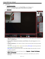
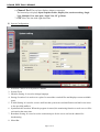
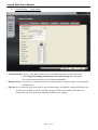
i-Guard DVR User’s Manual
Contents
System Requirement
Installation
Operation
Q&A
Troubleshooting
Page 02
Page 02
Page 03
Page 13
Page 14
Page 1 of 14
i-Guard DVR User’s Manual
A.
B.
System Requirement
Device
Minimum Request
Suggestion
CPU
P4 2.0GHz or other with same level
P4 3.0GHz or other with same level
RAM
512MB
1GB
Network
Equipment
Yes
Resolution
800*600 24bits
IP Cam
1 set at least
1024*768 24bits
Installation
1. Insert the CD to the CD drive. Auto-install menu will be popped up. Please select “Install
i-Gurad DVR” to carry out the installation.
2. If an old version had been installed into your computer, the system will prompt you to execute
update.
3. Follow the on-screen instruction to finish the installation.
Page 2 of 14
i-Guard DVR User’s Manual
C.
Operation
I.
Activating the Software
Method (1): Click the shortcut of i-Guard DVR on your desktop screen.
II.
Method (2): Run Start\Program Files\i-Guard DVR\i-Guard DVR.
Main Screen
1. Real View Screen: Four cameras can be monitored at one time and the system supports the
function of Click-To-Go.
2. System Tools: Minimized, Switched to small Window, Close the Program from left to
right side.
3. Channel Indicators: Click CH01 to CH04 to switch into that channel with single channel
view mode.
The center is status light; Yellow Light means stand by; Blue Light means being monitored;
Green Light means Detecting(recording).
Blue Light on the right side means audio is open; Black Light means the audio is closed or
no audio is supported
4. Main Menu: From the top to the bottom, they are Snapshot , Detect, Web Server,
Setup, and Playback.
5. Status Bar: It displays current time, date, system status, and hard disk space (while in
Detecting)
Page 3 of 14
i-Guard DVR User’s Manual
6. Channel Tool: The top layer displays alarms or messages
The bottom layer displays Open Snapshot Folder, Display Size, motion tracking, Single
View, Multiple View, Auto pan、Night View, PT go Home.
7. PTZ: Move the lens with eight directions.
III. System Configuration
1.
2.
3.
4.
5.
6.
7.
8.
Selection: Choose to set System or Channel.
System Tools
Interface Setting: It is used to change language.
Storage Location: It is used to set a place for stored the recorded files and displays current available
space.
E-Mail Setting: It is used to set an e-mail box that system can send notification and mail a test letter
to the specified mailbox.
Synchronized Execution: When the program is started, the monitoring function or web server will be
activated at the same time.
Broadcast Setting: It is used to set the connection port for the server and set the channel for
broadcasting.
Menu Bar
Page 4 of 14
i-Guard DVR User’s Manual
IV. Channel Setting- Image Source
1. Setting Tool Bar: There is only Image Source tab for the channel that has not been activated.
After Trigger Recording, Motion detect and Alart setting tabs will appear.
For current selected tab, the text will be shown in blue.
2. Remote Server: It is used to set channel activation, camera position, connection port, account number
and password.
3. IP Cam: It can detect the type of the camera and current settings. In addition, setting modification for
each item can be done in this field. If the settings here have been modified, all the users
connected to this IP Cam will be influenced with the new settings.
Page 5 of 14
i-Guard DVR User’s Manual
V.
Channel Setting – General Setting
1. Name: Set the name and description for the selected channel.
2. Text Display: Add channel information, date, time or on the screen.
Note: Recording or broadcasting also will be influence by the settings in Text Display.
Page 6 of 14
i-Guard DVR User’s Manual
VI. Channel Setting – Image Adjustment
1. Screen Adjustment: It supports Flip Horizontal and Flip Vertical, and Rotation with 360°
Page 7 of 14
i-Guard DVR User’s Manual
VII. Channel Setting – Recording
1. Resolution Setting: Set the quality of the recording. The more the resolution is, the higher the quality
and the larger the files will be.
2. Recording Type: It can be divided into Non Record, Scheduling and Record-at-click.
Scheduling Recording and Record-at-click also be divided into Full Time
Recording and Recording if Triggered.
3. Schedule: It displays message while in Scheduling Recording type.
It allows users to add, modify or delete the schedule. Also it support multi-scheduling.
Page 8 of 14
i-Guard DVR User’s Manual
VIII.Channel Detection-Motion detect
1. Display Screen: It can display the detected fields with green rectangle on the screen.
2. Field Setting: In this filed, you can add, delete the detected field
Test motion detect can run a real test if the displacement of the object can be
detected or not.
3. Sensitivity: When the sensitivity is set in “High”, little displacement of the image will be judged
with triggering. When the sensitivity is set in “Low”, only large of displacement will
be judged with triggering.
Page 9 of 14
i-Guard DVR User’s Manual
IX. Channel Setting – Alarm
1. Vibration: When there is an alarm, the screen will vibrate to warn the user.
It the program is minimized or move to edge of the screen, it will be recover to the
center of the screen and vibrate automatically.
If the program is switched by Small Window mode, the screen will not vibrate.
2. Warning Message: When there is an alarm, user defined alarm message will be displayed on the
Channel Tool of the main screen.
3. Sound Effect: When there is an alarm, a built-in sound effect or used defined sound will be sent out
to warn the user.
4.E-mail Alarm: When there is an alarm, the system will send a letter to the mail box that user set in
E-mail Setting field to notify the receiver. One to five snapshots will be attached
with the mail.
Page 10 of 14
i-Guard DVR User’s Manual
X.
Playback
1. Image Area: The content of the film and seconds will be shown in this field.
2. System Tools
3. Query Tool: Inquire all the saved recorded files within certain time for some channel and display
all the files in the list.
4. Intelligence Search: The usage is the same as Motion Detection. It can detect if there is any
displacement with certain area in the film.
5. Lists: It will display the result of the inquiry and allows user to delete selected file or open the
folder that stores recorded files.
6. Shuttle(Time Axis): It can judge which time point that film is played currently. Also, it can jump to
the specified time point of the film directly.
7. Play Toolbar: From left to right side, they are Play(Pause), Stop, Previous, Playback, Fast, Next.
8. Transmission Toolbar: Supports one to sixteen times of Transmission.
9. Snapshot Toolbar: From left to the right side, they are Capture and Open Snapshot Folder.
Page 11 of 14
i-Guard DVR User’s Manual
Small(Mini) Window
1. System Tools: From left to right, they are Capture, Recover to Main Screen.
2. Small Window: It can switch among four channels (by turn) and be dragged to any place of the
screen.
Page 12 of 14
i-Guard DVR User’s Manual
D.
Q &A
Q1: Why some buttons on Channel Tool of the Main Screen cannot be pressed?
A1: These functions (e.g., Displacement Tracing, Auto Cruise) can be used only the screen has been
switched into Single Channel View.
Q2: Why the system settings and playback function of recording cannot be used?
A2: When the Monitoring or Server function is activated, the system will not allow users to configure
system settings and use playback function. Simply close monitoring/server function. And then try again.
Q3: Why some buttons on the main screen will be shown in deep-gray, slight-gray, orange and blue?
A3: Deep-gray means that function cannot be used during certain mode, or the device does not support
such function. Slight-gray means such function can be used. Orange means the mouse cursor is
placing on the button. Blue means the mode used currently or such function is activated at present.
Q4: Why can’t I use PTZ, Lens Zero or Auto Cruise?
A4: Such modes must be used within Single Channel View mode. If you cannot use these functions after
switching into Single Channel View mode, that means the device does not support PTZ.
Q5: Should I type IP address if I want to use Image Source function? I do not have static IP. Can I use
DDNS?
A5: This program supports DDNS. It will be OK if you type IP address or DNS address.
Q6: What is Click-To-Go?
A6: In the Real Monitor window of Main Screen, when you click the left mouse button, the lens will
move to the place that mouse stops. That place will become the center of the main screen. You can
use this function no matter in Single Channel View or Multi-channel View mode. Yet it is not
available for the device that does not support PTZ.
Q7: Why recording cannot start after pressing the monitoring button?
A7: Please check the recording settings on the Channel Setting page. It might be that such channel was set
by no recording, scheduling recording or recording if triggered.
Q8: I find some screen is stopped/disturbed in the real-time monitoring screen.
A8: Please check the connection quality of the network and check if the IP Cam is run normally or not.
After checking all of these and removing the problems, the program will try automatically again.
Page 13 of 14
i-Guard DVR User’s Manual
E.
Troubleshooting
1. When the program is starting or after setting the system configuration, the error message “Can
not connect to following channel(s): CH**” will appear
It means that the system cannot detect IP Cam. It might be caused by wrong IP address, trouble in
network or something wrong happened to IP Cam.
2. When the program is starting or after setting the system configuration, the error message “Can
not import to following channel(s): CH**” will appear.
It means that the remote equipment might not be IP Cam, but other Web Server. Please check the IP
address that you have entered again carefully.
3. After recording for a long time, the program will have no response; or after finishing the
program, the messages of “No Buffer Space Error”, “Virtual RAM insufficient” will appear.
It means the real RAM of the computer is under the minimum request (512MB). It is suggested to use
a computer with 1GB of RAM or above.
4. An error message of “System change display setting error!” appears while starting the program.
It might be that the user is using remote control software (remote desktop, PC Any Where, VNC, etc.)
to access into the program. Such thing results in the color bytes of system not 24 bits or above.
5. For other error message, or do not know what the error message is.
Please contact with the customer service member.
Page 14 of 14