1
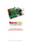
BerryClip+ 6 LED Buzzer Board
The PCB
The PCB is labelled to identify where each component should be placed.
P1
P2
BUZZ1
S1
S2
R1-R6
R7,R9
R8,R10
LED1,2
LED3,4
LED5,6
Bumper
26-way header
13-way pin header
5v buzzer
Micro-switch
Micro
330 ohm (Orange-Orange-Brown)
1K ohm (Brown-Black-Red)
10K ohm (Brown-Black-Orange)
Red LEDs
Yellow LEDs
Green LEDs
Rubber bumper
Take care to ensure the 1K and 10K resistors are placed in the correct positions.
Take a look at the photos to ensure you solder the two headers onto the correct side
of the board.
The LEDs have a short leg (Cathode) and long leg (anode). Make sure the long leg is
inserted into the hole nearest the P1 Header. The short leg should be inserted into
the hole nearest the resistor.
http://www.raspberrypi-spy.co.uk/