1
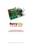
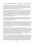
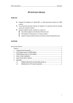
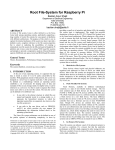
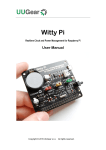
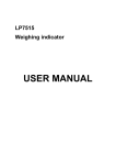
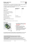
BerryClip+
6 LED Buzzer Board
The quick and easy way to
experiment with the Raspberry Pi
Raspberry Pi is a trademark of the Raspberry Pi Foundation
BerryClip+ 6 LED Buzzer Board
Introduction
The BerryClip+ is an enhanced version of the popular BerryClip add-on board. It is a
simple, cheap and easy to use addition to the Raspberry Pi. It plugs directly onto the Pi's
GPIO header and provides 6 coloured LEDs, 1 Buzzer, 2 Switches and a 13 pin header. It
can be controlled using any programming language that can manipulate the GPIO pins
and this includes Python and C. The 13 pin header allows additional components and
sensors to be added.
Parts
The kit of parts includes :
1 Circuit board
2 Red LEDs
2 Yellow LEDs
2 Green LEDs
6 330 ohm resistors
2 1K ohm resistors
2 10K ohm resistors
1 Buzzer
2 Switches
1 26 way header connector
1 13 way pin header
1 Rubber bumper
Resistor Colour Codes
The value of a resistor is indicated by bands of colour. The resistors on the BerryClip+ will
have the following colour codes :
330 ohm
Orange-Orange-Brown
1K ohm
Brown-Black-Red
10K ohm
Brown-Black-Orange
http://www.raspberrypi-spy.co.uk/
BerryClip+ 6 LED Buzzer Board
The PCB
The PCB is labelled to identify where each component should be placed.
P1
P2
BUZZ1
S1
S2
R1-R6
R7,R9
R8,R10
LED1,2
LED3,4
LED5,6
Bumper
26-way header
13-way pin header
5v buzzer
Micro-switch
Micro
330 ohm (Orange-Orange-Brown)
1K ohm (Brown-Black-Red)
10K ohm (Brown-Black-Orange)
Red LEDs
Yellow LEDs
Green LEDs
Rubber bumper
Take care to ensure the 1K and 10K resistors are placed in the correct positions.
Take a look at the photos to ensure you solder the two headers onto the correct side
of the board.
The LEDs have a short leg (Cathode) and long leg (anode). Make sure the long leg is
inserted into the hole nearest the P1 Header. The short leg should be inserted into
the hole nearest the resistor.
http://www.raspberrypi-spy.co.uk/
BerryClip+ 6 LED Buzzer Board
Assembly & Soldering
If you have never soldered before or you need a quick refresher then I can recommend the
"Soldering Is Easy" comic :
http://mightyohm.com/files/soldercomic/FullSolderComic_EN.pdf
or this SparkFun page :
http://www.sparkfun.com/tutorials/106
Recommended Soldering Sequence :
Solder 1 26-way header
Solder 8 resistors
Solder 6 LEDs
Solder 1 switch
Solder 1 buzzer
Solder 13-way pin header
When soldering the headers make sure you don't use too much solder or you may shortcircuit the pins underneath the PCB.
Once the components are soldered :
Visually check your solder joints and ensure there are no stray blobs or splashes
of solder that might short-circuit any pins.
Remove the label on the buzzer.
Stick rubber bumper to underside of board so it will rest on large silver capacitor
(C6) on the Raspberry Pi.
If possible use a multimeter to check there are no short-circuits between adjacent
header pins.
Plug the board onto your Raspberry Pi. Stand back and admire your work.
http://www.raspberrypi-spy.co.uk/
BerryClip+ 6 LED Buzzer Board
Software Setup
To start with you will need a working SD card. I would recommend starting
with a fresh copy of Raspbian. This image can be downloaded from from
raspberrypi.org/downloads
Once you've got an SD card prepared put it in your Pi, power it up and login
with default user name and password (‘pi’ and ‘raspberry’)
You will now be located in the ‘pi’ user home directory (‘/home/pi/’).
Type the following commands pressing the Enter key at the end of each line :
mkdir berryclip_plus
cd berryclip_plus
wget https://bitbucket.org/MattHawkinsUK/rpispy-berryclip-plus/get/master.tar.gz
tar -xvf master.tar.gz --strip 1
The above lines perform the following functions :
Makes a new directory called ‘berryclip_plus’
Navigates into that directory
Grabs an archive of all the files from the BitBucket.org website
Extracts the files to your Pi
The script will download an instruction file and a set of example Python scripts.
To list the downloaded files type :
ls -l
You can use the following command to remove the gz archive as we don’t need that now
we have extracted the files :
rm master.tar.gz
http://www.raspberrypi-spy.co.uk/
BerryClip+ 6 LED Buzzer Board
Run Some Example Python Scripts
The following example Python scripts are available :
berryclip_01.py – Test LEDs only
berryclip_02.py – Test Buzzer only
berryclip_03.py – Test Switches only
berryclip_04.py – Test LEDs and Switches
berryclip_05.py – Test LEDs, Buzzer and Switches
berryclip_06.py – LED sequence
berryclip_07.py – Dice Simulator
berryclip_08.py – Reaction time game
berryclip_09.py – Random LEDs
berryclip_10.py – Multiple LED sequences in a loop
berryclip_11.py – Traffic light simulator
berryclip_12.py – Morse code generator
To run a script you can use the following command :
sudo python berryclip_01.py
To quit a running Python script use [CTRL-C].
To view a text file or Python script you can use the command :
cat berryclip_01.py
http://www.raspberrypi-spy.co.uk/
BerryClip+ 6 LED Buzzer Board
Modifying Scripts
Once you have tested your BerryClip+ and tried the example scripts you can start to
develop your own examples. You can use any text editor you prefer to edit the scripts but
here are some quick tips.
Copy an existing scripts to a new file by using :
cp berryclip_01.py myfile.py
Edit a script in the nano text editor using :
nano myfile.py
Make your changes and save using CTRL+O .You can quit nano by pressing CTRL+X.
Adjusting the time.sleep() statements is a good thing to start with. Or maybe adding
additional print statements.
http://www.raspberrypi-spy.co.uk/
BerryClip+ 6 LED Buzzer Board
Additional Information
The following information is provided for those that are simply curious or are looking to
modify their BerryClip+.
Hardware Reference
Here is a list of components, the header pins (P1) they connect to and the GPIO reference
you can use you control them :
LED 1
LED 2
LED 3
LED 4
LED 5
LED 6
Buzzer
Switch 1
Switch 2
P1-07
P1-11
P1-15
P1-19
P1-21
P1-23
P1-24
P1-26
P1-22
GPIO4
GPIO17
GPIO22
GPIO10
GPIO9
GPIO11
GPIO8
GPIO7
GPIO25
13 Pin Header (P2)
P2-01
P2-02
P2-03
P2-04
P2-05
P2-06
P2-07
P2-08
P2-09
P2-10
P2-11
P2-12
P2-13
3.3V
5V
Ground
GPIO2
GPIO3
GPIO14
GPIO15
GPIO18
GPIO27
GPIO23
GPIO24
3.3V
Ground
P1-01
P1-02
P1-06
P1-03
P1-05
P1-08
P1-10
P1-12
P1-13
P1-16
P1-18
P1-17
P1-25
3.3V
5V
Ground
GPIO2 I2C0_SDA
GPIO3 I2C0_SDA
GPIO14 Serial TX
GPIO15 Serial RX
GPIO18
GPIO27
GPIO23
GPIO24
3.3V
Ground
Be aware that some of the GPIO assignments are different on Raspberry Pi Rev 1 and
Rev 2 boards. Rev 1 boards do not have the two large mounting holes in the PCB.
Rev 1 GPIO0 = Rev 2 GPIO2
Rev 1 GPIO1 = Rev 2 GPIO3
Rev 1 GPIO21 = Rev 2 GPIO27
http://www.raspberrypi-spy.co.uk/
BerryClip+ 6 LED Buzzer Board
LED Currents
The LED current limiting resistors are 330Ω. The voltage provided by the GPIO pins is
3.3V. The LEDs drop approximately 2-2.2V. This leaves the resistor dropping 1.1-1.3V. The
resistors have a tolerance of 5% so could vary in value between 310Ω and 350Ω.
So using Ohm's Law :
we can calculate that the LEDs each draw between 3.1mA and 4.2mA.
http://www.raspberrypi-spy.co.uk/
BerryClip+ 6 LED Buzzer Board
Circuit Diagram
Here is a circuit diagram showing how the LEDs, switches and buzzer are connected to
the GPIO header via the resistors.
19 December 2013
Raspberry Pi is a trademark of the Raspberry Pi Foundation
http://www.raspberrypi-spy.co.uk/