1
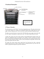
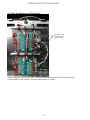
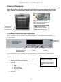
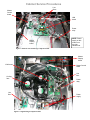
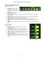
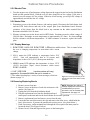
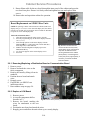
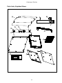
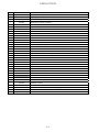
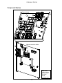
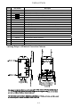
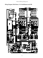
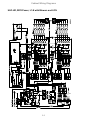
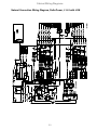
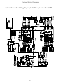
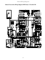
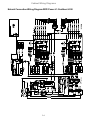
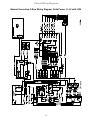
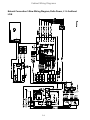
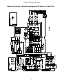
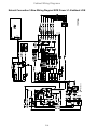
UHC-HD Service, Parts Manual for 6, 3-Row Models, Fan-Cooled and Natural Convection Frymaster, a member of the Commercial Food Equipment Service Association, recommends using CFESA Certified Technicians. *8196606* 24-Hour Service Hotline 1-800-551-8633 Price: $6.00 819-6606 02/2015 NOTICE IF, DURING THE WARRANTY PERIOD, THE CUSTOMER USES A PART FOR THIS MANITOWOC EQUIPMENT OTHER THAN AN UNMODIFIED NEW OR RECYCLED PART PURCHASED DIRECTLY FROM FRYMASTER DEAN, OR ANY OF ITS AUTHORIZED SERVICE CENTERS, AND/OR THE PART BEING USED IS MODIFIED FROM ITS ORIGINAL CONFIGURATION, THIS WARRANTY WILL BE VOID. FURTHER, FRYMASTER DEAN AND ITS AFFILIATES WILL NOT BE LIABLE FOR ANY CLAIMS, DAMAGES OR EXPENSES INCURRED BY THE CUSTOMER WHICH ARISE DIRECTLY OR INDIRECTLY, IN WHOLE OR IN PART, DUE TO THE INSTALLATION OF ANY MODIFIED PART AND/OR PART RECEIVED FROM AN UNAUTHORIZED SERVICE CENTER. THE CABINET IS NOT SUITABLE FOR OUTDOOR USE. WHEN OPERATING THIS UNIT, IT MUST BE PLACED ON A HORIZONTAL SURFACE. THE CABINET IS NOT SUITABLE FOR INSTALLATION IN AN AREA WHERE A WATER JET CAN BE USED. THIS APPLIANCE MUST NOT BE CLEANED WITH A WATER JET. FOR YOUR SAFETY DO NOT STORE OR USE GASOLINE OR OTHER FLAMMABLE VAPORS AND LIQUIDS IN THE VICINITY OF THIS OR ANY OTHER APPLIANCE. DO NOT OPERATE OR SERVICE THE CABINET WITHOUT FIRST READING THIS MANUAL. DO NOT OPERATE THE CABINET UNLESS IT HAS BEEN PROPERLY INSTALLED AND CHECKED. DO NOT OPERATE THE CABINET UNLESS ALL SERVICE AND ACCESS PANELS ARE IN PLACE AND PROPERLY SECURED. DO NOT ATTEMPT TO REPAIR OR REPLACE ANY COMPONENT OF THE CABINET UNLESS ALL POWER TO THE UNIT HAS BEEN DISCONNECTED. USE CAUTION WHEN SETTING UP, OPERATING, OR CLEANING THE CABINET TO AVOID CONTACT WITH HEATED SURFACES. USE CAUTION WHEN LIFTING THE UHC-HD. THE UNIT WEIGHS 200 POUNDS. THREE TO FOUR PEOPLE, USING STANDARD SAFE LIFTING PRACTICES, WILL BE NECESSARY TO HANDLE THE CABINET. Table of Contents Theory of Operation 1-1 Service/Software Procedures 2-1 Troubleshooting 3-1 Illustrated Parts List 4-1 Wiring Diagrams 5-1 Cabinet Service Procedures 1 Functional Description Master Control Display Power switch Timer: displays on row board remaining time for all active timers. Row Mode key Timer keys Timer key Temperature: displays on row board plate temperature, alternating between top and bottom. Note: The illustrations for these service procedures are of the 6‐row full size UHC‐HD. 1.2 Theory of Operation The cabinet operates on 208-250VAC 50 or 60 cycle single-phase power. The main switch activates a relay, which supplies line voltage to two distribution boards, three cooling fans and a power supply. The power supply provides 5VDC to the master control board and the distribution boards. The fans were removed from later versions of the UHC-HD and the power supply moved to the right side. The cabinets, functionally, are otherwise the same. The cabinet without fans has a flat top. A ribbon cable connects the master control board to both distribution boards. Ribbon cables also connect the distribution boards to the displays. The resistance of RTD’s, attached to the heater plates, is monitored by the distribution boards. The board switches power through solid-state relays to the heater plates when the resistance, which is used as an indicator of temperature, falls out of the range for the product held in the cabinet. The switch, relay, master control, master control board, line filter board, line filter, cooling fan (original design) and power supply (original design) are mounted under the top of the unit. The cabinet is programmed using the key pad on the front bezel. 1-1 Cabinet Service Procedures 1.3 Start Up Indicators and Test Points Distribution boards shown with ribbon cables removed. Upon startup, the cabinet beeps. LED’s on the distribution boards flash. The displays show the version number of the cabinet’s firmware and then the row’s status. 1-2 Cabinet Service Procedures 2 Service Procedures DANGER: Failure to disconnect power from the unit before servicing could result in serious injury or death. The cabinet power switch DOES NOT disconnect all incoming power to the cabinet. Fig. 2: Tabs in the topcap extend to holes in the cabinet. The top is secured with at the tabs with screws. Fig. 1: The sides are held in place by screws near the base of the unit on each side. NOTE: Cabinet shown is original UHC-HD. The later design with a flat top disassembles the same way. 2.1 Updating Software/Capturing Configurations The five sections of software on the cabinet can be updated individually. To ensure compatibility between cabinet software and replacement boards, the software should be updated to the latest version at any board replacement. Follow the directions below. Keypad: Enter programming d Power Switch: Cycle power between each revision update. Programming key: Press prior to entering programming code. OK: Press to confirm choices. Arrows: Scroll to choices. Software updates use the master control display to enter programming codes, scroll to areas to be revised, respond to questions and exit. The control is annotated above. The arrow and OK buttons are illuminated when active. Check Existing Versions 1. 2. 3. 4. 5. With the unit powered up, press the programming key. Screen scrolls Enter Access Sequence. Enter 090809 on keypad. Press OK. Scroll with arrow keys to view all software revision numbers: Main Boot Loader Master Display Distribution Board Row Display 6. Press OK. 2-1 NOTE: If the master control displays an error message during the install process, turn the cabinet off for 30 seconds and back on. Repeat install steps. Cabinet Service Procedures Update: Boards 1. 2. 3. 4. 5. 6. 7. 8. 9. 10. 11. 12. 13. 14. 15. 16. 17. Loading Sequence Software should be loaded in this sequence: Main Board Language Row Display Distribution Boards If the software update only involves a few of the components, follow the loading sequence, skipping the unneeded component. Turn power off. Insert flash drive in USB port located on cabinet bezel. Turn power on. Cabinet displays version numbers followed by current menu setting. Press programming key. Screen scrolls Enter Access Sequence. Enter 98765 with keypad. Press OK. Scroll with arrow key until software section (see loading sequence box) to be updated is displayed on master control board. Press OK. Incompatibility Message Screen displays Copying Files, Please Wait. This takes The cabinet can display an incompatibility several minutes. message during software upgrades. The Screen messages will vary, depending on software section buttons will remain active. Follow the being installed. Follow screen instructions. Screen displays Complete. loading sequence and the incompatibility is Press OK. corrected as the software components are Screen displays Main Boot Loading and a percentage of loaded. completion. After 100% is displayed, screen goes blank and returns to menu display. Turn cabinet off for 30 seconds and back on. Update: Language File 1. 2. 3. 4. 5. 6. 7. 8. 9. 10. With the unit on, press program button. Enter 090709 with the keypad. Press OK. Screen displays Reconfigure OK or Cancel. Press OK. Screen displays Please Wait Lang Bin. Screen displays 9 files copied. Press OK. Screen returns to normal display. Turn cabinet off for 30 seconds and back on. Capture Cabinet Menus/Configurations The menu items and cabinet configurations in a cabinet can be captured and used to configure cabinets with identical software setups. Follow the instructions below to capture the menus and configuration from a cabinet. 1. Insert an empty flash drive in the USB socket on the cabinet with menus and configurations to be copied. The configuration of a cabinet can be captured on an empty 2. Press the programming key. flash drive for transfer to cabinets with the same software setup. 3. Enter 759248 with the keypad. 4. Press OK. See Exporting and Importing named 5. The master control will display Copy configurations in the user’s manual, 819-6560, on from UHC to USB. page 3-11. 2-2 Cabinet Service Procedures 6. Press OK. 7. The master control displays Please Wait… as files are transferred to the flash drive, changing to the number of files copied when the process is complete. 8. Press OK. 9. Remove flash drive. 10. Cabinet returns to normal display. Configure Cabinet with Menu/Configuration Captured on another Cabinet 1. Place a flash drive with only a captured menu/cabinet configuration in the root file into the USB port of a cabinet to be identically configured. 2. Press the programming key and enter 090709 with the keypad. A cabinet configuration can be transferred to multiple cabinets with a captured configuration held on a flash 3. Press OK. drive. 4. The master control will display Reconfigure OK or Cancel. 5. Press OK. 6. The master control will display Please wait… as the files are updated, changing to the number of files copied. 7. Press OK. 8. The cabinet will return to the original menu setting, changing row position displays to match items introduced with the configuration transfer. Cabinet Access Codes Code 759248 Function Capture cabinet configuration to flash drive 98765 Load software updates from USB drive 1955 Enter manual programming mode (see operation manual). 4557 LON Works service pin 090809 View software versions 1111 Service test mode 090709 Update language file 11111 Setup: Change from 6-row to 3-row, front-display only (SPOD) for 3 or 6row cabinets. See instructions for use on page 2-10. 2-3 Cabinet Service Procedures 2.2 Placing the cabinet in Service Mode The cabinet can be put in service mode, a diagnostic settings which allows the heater plates to be controlled individually, brightness settings on the displays adjusted and re-addressing for unique arrangements of bezels. Follow the steps below : Switching Heater Plates Off Individually When troubleshooting, it may be useful to switch heater plates off individually. Follow the instructions below: 1. 2. 3. 4. Press the programming key. Enter 1111 at the Enter Access Sequence prompt. The screen will scroll Row 1 Top Heater Off; pressing OK turns it back on. Voltage can be measured between the plate-specific heater leads on the distribution board and the common block to the right of the distribution board as the heater plates are switched, individually, on and off. 5. Scroll to other plates with . 6. Ensure the plates are on before backing out of the Service Mode with the . Adjusting Display Brightness When multiple row positions are timing the same item, the display with the least remaining time is the brightest. All others are dimmer as are positions not actively timing a product. The relative brightness of the bright display and the dim display can be adjusted. Follow the instructions below: 1. 2. 3. 4. 5. Press the programming key. Enter 1111 at the Enter Access Sequence prompt. Press OK. The screen will scroll Row 1 Top Heater Off. Scroll with through all the Heater Plate prompts until the screen displays Press OK to Adjust Bright Row Display. 6. Press OK. 7. The cabinet’s row displays become Decrease Increase 88888 20 8. Press the timer button next to the Decrease display to lessen the brightness; the number displayed at the right will decrease. Press the timer button next to the Increase display to increase the brightness; 20 is the maximum. 9. Press OK. The display becomes Adjust Dim Intensity. The cabinet’s row displays become Decrease Increase 88888 03 10. Press the timer button next to the Decrease display to lessen the brightness; the number displayed at the right will decrease. Press the timer button next to the Increase display to increase the brightness; 1 is the minimum. 11. Press OK. 12. Cabinet returns to menu display. 2-4 Cabinet Service Procedures Readdressing the Cabinet Addressing, or assigning a position-specific component such as a display or distribution board, is done automatically by the cabinet on startup. Communication errors can occur on start-up after a board installation however. If so, follow the instructions below to readdress the cabinet. This process can also be used during troubleshooting when displays are connected out of synch with their associated bezel on the same row level. 1. 2. 3. 4. 5. 6. 7. 8. NOTE: Readdess the Press the programming key. cabinet if multiple displays Enter 1111 at the Enter Access Sequence prompt. are removed and reinstalled during a service procedure, The screen will scroll Row 1 Top Heater Off. Scroll with through all the Heater Plate prompts until the such as a heater plate replacement. screen displays Press OK to Re-Address. Press OK. Screen Displays Please Power Cycle Off. Turn the cabinet off and back on. The cabinet will start in the normal start-up sequence. 2.3 Accessing the Electronic Components 1. The component shelf is accessed by removing two screws on each side of the unit (Fig. 1). 2. Lift and remove the sides, which exposes screws that hold the top in place (Fig. 2). 3. The components for the original cabinet and the natural convection model are annotated below (Fig. 3,4). NOTE: The component shelf changed with the introduction of the natural convection UHC-HD. The fans are removed and the power supply is mounted on the right side of the unit. 2-5 Cabinet Service Procedures Line filters Master Control board LON board Power relay NOTE: Power supply on this model is on the right cabient side. Master Display board Figure 3: Natural convection design component shelf. Master Display board LON board Fans: are specific to NOTE: The cooling fans regions of the cabinet rest on ducts, and cool and ducted to direct specific regions of the the air flow. cabinet. Master Control board Line filter Cooling fans Power relay Line filter Power supply Relay Figure 4: Original design component shelf. 2-6 Cabinet Service Procedures 2.4 Circuit Board LED Diagnostics Master Control Board: HB LED is a heartbeat; should be flashing when in the normal in- use mode. Flash rate is not Fig. 5: Master Control Board LED's critical. ACT LED similar to HB but flashes at a faster rate. OK LED toggles each time a valid communication packet is sent and received. Normally a very fast flicker. ERR LED toggles when a communication error is detected; it’s not unusual to see a flash, but regular flashing means communications problems. LED5 and LED6 used for programming/debugging; have no diagnostic function. LED7 When lit, the master control is executing a time or temp query operation on the front side. LED8 When lit, the master control is executing a time or temp query operation on the back side. Distribution Board HB LED is a heartbeat LED; toggles on / off to indicate processor is running. ACT LED flashes when it receives a valid communication packet; it should be flashing every few seconds or faster. LED3 Toggles if there is a communications error on a packet directed to the distribution board. Can flash on occasion; shouldn’t flash regularly. LED1 flashes if there is voltage being applied to one or more heaters on that distribution board; one or more plate is calling for heat. Fig.6: Distribution Board LED's 2-7 Cabinet Service Procedures 2.5 Tests 2.5.1 Power Supply 1. Disconnect power and check all terminals and connections for loose or disconnected wires. 2. Apply power and check for 5VDC at the power-in terminal on the distribution board and chassis ground. 2.5.2 RTD 1. Remove the leads from the suspect RTD and test for resistance. Selected temperatures and resistances are show in chart at right. NOTE: After testing, reconnect all leads to their original positions. 2.5.3 Distribution Boards 1. Check for line voltage between the heater plate terminal on the board and the terminal block for the suspect heater. Note: Line voltage is only seen when the row is calling for heat. 2. Check for line voltage between Distribution Board Message Test: Unplug top board. the power input Board 0 message; bottom board is 1. terminal and the Board 1 message; bottom board is 2. See Board Error Messages terminal block. Page 3-1. 3. Check for +5VDC at the power-in terminal and the terminal block for the power supply. Sensor (°F) Resistance Sensor (°C) 60 70 80 90 100 110 120 130 140 150 160 170 180 190 200 210 220 230 240 250 260 106.065 108.224 110.380 112.532 114.680 116.825 118.966 121.104 123.239 125.369 127.496 129.620 131.740 133.856 135.969 138.078 140.184 142.286 144.385 146.480 148.570 15.55 21.11 26.66 32.22 37.77 43.33 48.88 54.44 60.00 65.55 71.11 76.66 82.22 87.77 93.33 98.88 104.44 110.00 115.55 121.11 126.66 RTD resistance chart NOTE: After testing, reconnect all connections to their original positions. 2.5.4 Display 1. Remove power from unit. 2. Connect the ribbon cable from a suspect display to the connector of a properly working display to isolate the problem to the display or the distribution board. 3. Reapply power to cabinet. 2-8 Fig. 7: Distribution board shown with display cables removed. Cabinet Service Procedures 2.5.5 Shorted Triac 1. Turn the suspect row off and measure voltage between the suspect heater lead on the distribution board and the terminal block. With the row off, there should be no line voltage. If the triac is shorted, you will measure AC line voltage. If the triac is half waving, you will get DC voltage of approximately one-half the line AC voltage. 2.5.6 Heater Plate 1. Disconnect power to the cabinet. Remove side and top panels. Disconnect the black heater lead and the RTD leads (brown and red) of the suspect plate from distribution board. Measure resistance of the heater from the black lead to any terminal on the white terminal block. Resistance should be 140-150 ohms. 2. Measure resistance across the brown and red RTD leads. Resistance must be within a range of 104-148 ohms. Resistance at room temperature is approximately 107 ohms. See chart on Page 2-4 for resistance at different temperatures. If either resistance is incorrect, replace the heater plate. 2.5.7 Display Meanings 1. ROW TEMP HIGH OR ROW TEMP LOW and no audible alarm. This is normal when the row is changing temperature in association with a menu change. 2. LLLL means the RTD indicates a temperature below 50°F (10°C). Unit will automatically heat at 20 percent until temperature is above 50°F (10°C), then operate normally. 3. HHHH means RTD indicates the temperature is above 255°F (124°C), but below "Open" circuit resistance, which causes SENS ALARM. 4. UHC VERSION _ _ _ (version number will vary) appears for five seconds when the unit is turned on. 5. The cabinet also displays a variety of error messages, which are shown on page 3-1. Fig. 8: Two screws (see arrows) at the base of each side of the cabinet secure the sides. 2.6 Removing/Replacing Bezels NOTE: Readdess the cabinet if 1. Remove power from unit. multiple displays are removed and 2. Remove screws at the base of each side and remove side reinstalled during a service panels. (See figure 8.) procedure, such as a heater plate 3. Unplug the bezel from the distribution board. replacement. See page 2-5. 4. Plug the replacement bezel into the distribution board, return power to the unit and test the bezel/cabinet for accurate operation. 5. Remove replacement bezel and remove power from the unit. 6. Loosen the hex nut which secures the row and remove the allen screw, which holds the bezel. Also remove, if present, the small bezel-securing screw. (See photo below.) 7. Push, if necessary, on the mounted bezel through the access port in the inner panel to loosen the bezel. (See Figure 9 below.) 8. Remove bezel; clean and degrease the groove in the heater plate. 2-9 Cabinet Service Procedures 9. Route ribbon cable for the new bezel through the inner panel of the cabinet and press the new bezel into place. Ensure it is firmly seated and tighten hex nuts and replace allen screws. 10. Return sides and reposition cabinet for operation. Board Replacement on SPOD/3 Row Units NOTE: IF replacing a master control board on a SPOD (front bezel displays only, 6 or 3 row) or 3-row dual side display unit, the cabinet must be reset for that style of operation. Service boards are defaulted to operate on 6-row dual display units. Follow the instructions below: 1. After the board is replaced, return power to the unit. 2. Press the programming key on the master display and enter 11111 (5 1’s). 3. Scroll through options on the master display with the illuminated key: 6 shelf single side; 6 shelf dual side; 3 shelf single side; 3 shelf dual side. 4. With the desired configuration displayed, press the illuminated OK key. 5. Are You Sure appears on the master display screen. 6. Press OK. Fig. 9 Loosen the hex bolt and remove the allen screw (arrows, upper photo). Some row positions may have an additional screw securing the bezel to the cabinet (lower photo). Push through the access port (arrow, upper photo), if necessary, to remove the bezel from the cabinet . 2.6. 1 Removing/Replacing a Distribution Board or Communication Board 1. Remove power. 2. Remove and mark the wires on the faulty component. 3. Remove the board by lifting it from its standoffs. 4. Position the new board and attach wires. 5. Reapply power. 6. If applicable, see SPOD/3-row instructions above. 7. Run readdress steps on page 2-4. 2.6.2 Replace a LON Board 1. Remove power. 2. Access the component shelf as describe in 2.3. Fig 10: A row is shown partially removed from the cabinet. 3. Remove the board, marking the wires for attachment to the new board. 4. Position the new board and attach the wires. 5. Reapply power and allow the unit to boot up to a steady display. 2-10 Cabinet Service Procedures 6. Continue with these steps if the cabinet is in a store with a LON system. 7. With a menu in the master display, press the programming button and enter 4557. 8. Press OK. 9. The display will scroll: Press OK to activate service pin. 10. Press OK. 11. WINK appears on the master display and OK is illuminated. 12. Press OK. 2.6.3 Removing a Row 1. Remove the sides and top as shown in earlier steps. Disconnect the faulty row from the distribution board, and terminal block. NOTE: Readdess the cabinet if multiple displays are removed and reinstalled during a service procedure, such as a heater plate replacement. See page 2-5. 2. Remove the bezels on each end of the affected row, as shown in earlier steps, and the necessary adjacent bezels to remove the row. 3. Remove wire wraps from wiring harness holding heater and control wires for affected row. 4. Lifting slightly, carefully slide the malfunctioning row out of the cabinet. Do not allow the row to contact or damage the controls of the unit below (Fig. 10). 2.6.3 Replace Heater Plate/RTD 1. Remove row as shown above. 2. Run your fingers around the outside surface of the row assembly. There are four raised areas. These are the setscrews, which hold the heater plate to the spacer. Punch holes in the insulation, directly above the location of the setscrews. (Fig. 10, 11). 3. Use an allen wrench to loosen the four spacer-setscrews along the edges of the plate. 4. Slide the malfunctioning plate out of the spacer. 5. Slide the replacement plate into position. Make sure the plate is inserted squarely. Tighten set screws. 6. Route the wires to one end of the row and wire tie the power wires together. Also wire tie the RTD wires together. Stand the row on the opposite end adjacent to the cabinet and feed the wires into the cabinet. 7. Carefully slide the row far enough into the cabinet to be stable. 8. On the opposite side, reach into the cavity and direct the wires through the appropriate grommets to reach the power and RTD connections on the distribution board. Fig. 11, 12: Find the set screws under the foil insulation and push through with an allen wrench. 9. Slide the row assembly completely into the cabinet and return the spacers between the heater plates. Ensure the row is evenly positioned in the cabinet. There must be sufficient space to allow the bezel tabs to fit between the outside row plate and the cabinet interior wall. 2-11 Fig. 13: The heater plate slides from the insulation. Cabinet Service Procedures 10. Replace the bezels. CAUTION Ensure the heater plate setscrews are tightened securely to the spacer. Tightening the setscrews will ensure the plate is properly grounded. 2-12 Cabinet Troubleshooting The master control display and the row displays show error messages when there is a problem. The messages are shown in the matrix below along with possible causes and diagnostic tests. Error Message Call service row display error Row number also displayed * Cause The master control board has lost communication with the specified board. Tests Turn the cabinet off and back on. Ensure there are no software incompatibilities. Inspect ribbon cable connections. Call service distribution board 0 error or Distribution Board 1 Error Call service distribution board 1 error or Distribution Board 2 error. The master control board has lost communication with the top distribution board. *Cabinets built after 11/1/10 display Board 1 for the top board. The master control board has lost communication with the bottom distribution board. *Cabinets built after 11/1/10 display Board 2 for the bottom board. A display connection can produce this display. Before replacing a distribution board, remove power from the unit and disconnect the displays from the affected distribution board. Return power to the unit and, one at a time, plug in the displays, cycling power each time. If the problem is display‐ related it will go away with the affected display disconnected. Turn the cabinet off and on, which can clear the problem if it is software related. Check top plate RTD output against chart on page 2‐4. Enter service code (see page 2‐1) and switch top plate on and off to ensure it is responding to cabinet circuits. Check for environmental causes: AC vents, cold trays, etc. Call service rate of rise top** Row’s top plate failed to reach required temperature in prescribed time window after startup or when switching between menus. Call service rate of rise bot ** Row’s bottom plate failed to reach required temperature in prescribed time window after startup or when switching between menus. Call service top row temp too high ** Call service bot row temp too high** Call service top row temp too cool** Call service bot row temp too cool ** Call service top sensor error hi temp** RTD sensor is producing a reading that is out of range. The problem can be a failed RTD, heater or distribution board. Call service bot sensor error hi temp** Call service top sensor error low temp ** Call service bot sensor error low temp** * Shown on master control display. ** Shown on affected row display. 3-1 Turn the cabinet off and on, which can clear the problem if it is software related. Check bottom plate RTD output against chart on page 2‐4. Enter service code (see page 2‐1) and switch bottom plate on and off to ensure it is responding to cabinet circuits. Check for environmental causes: AC vents, cold trays, etc. Compare plate temperature to displayed temperature. Compare plate RTD resistance to chart on page 2‐8. Switch plate on/off with service code to ensure it is responding to cabinet circuits. With plate on and calling for heat, check amp draw on leads between distribution board and heater plate. Amp draw on a properly functioning plate should be 1.67. Cabinet Troubleshooting Failure modes not accompanied by a master control display are shown below with possible causes and tests. Symptom Unit fails to power up; fans don’t run. Unit powers up and fans run; a display fails to light. Unit powers up and fans run; all displays fail to light. Possible Causes Tests No power to cord. Blown 20 amp fuse. Circuit breaker open. Broken or improperly seated ribbon cable. Defective display. Failed power supply. Rows heat improperly or not at all. Improper wiring on distribution board. Defective distribution board. Defective heater. Defective sensor. 3-2 Check for line voltage at the relay, power supply. Reset circuit breaker. Switch ribbon cable from functioning display to failed component to isolate problem. Check for 5VDC at communication board and distribution boards. Ensure heater leads and power inputs on the distribution boards are properly seated. Test for 208VAC input on distribution board and 208VAC output from heater leads to heater plate when the unit is calling for heat. Switch power leads from properly operating row to faulty row to isolate problem. Check resistance of RTD lead against temperature chart. See Page 2-4. Switch RTD lead from properly operating row to faulty row to isolate problem. Test continuity of heater plate. Cabinet Parts Parts Lists, Exploded Views 3 1 2 4 6 7 8 5a 9 5 11 10 12 15 13 14 4-1 Cabinet Parts Item Part Number Description 1 * 2 * * * 3 * 4 5 5a 6 * 7 1081897 1082519 8238032 8237931 8237932 8237931 8074882 8074989 8075111 8074911 8121306 8238031 8237930 8075112 Top Cap, with hump Top Cap, Natural Convection cabinet, flat top Rear Fascia, fan-cooled unit Rear Fascia, natural convection Rear Fascia, natural convection CE Rear Fascia, 3-row Circuit Breaker, 16 amp USB Port, sliding cover Time/Temperature switch Power switch Varistor, Metal Oxide Front fascia, fan-cooled unit Front Fascia, natural convection Master display overlay with ribbon cable * 8 9 * 10 11 12 13 14 15 * * * 8075156 8075111 8262781 8262782 1082167 8074857 8075508 1083357 1081990 1081991 1081990 1082823 2308307 Master display board (circuit board in master display assembly) Time/Temperature switch Bezel, with boards, front with short ribbon cable Bezel with boards, rear, with long ribbon cable Base Heater plate/RTD Distribution board Magnetic quick-reference card holder (natural convection units) Side, 6-row, left, vented (cabinet with fans) Side 6-row, right, not vented (cabinet with fans) Side, 6-row, vented, right or left (natural convection cabinet sides are not side-specific) Side, 3-row vented, right or left Bottom bezel fascia, front or rear Cordsets * * * * * * * 8072803 8074145 8072473 8263096 8263097 8263098 8263099 CE Cordset Australian Cordset Domestic Cordset Australian 90° Rear Exit Kit with cordset Australian 90° Rear Exit Kit with cord, no plug CE 90° Rear Exit Kit with Cordset CE 90° Rear Exit Kit without Cordset 4-2 Cabinet Parts Component Shelves Original design component shelf 1 3 4 2 Not to scale; placement varies 5 6 7 Natural convection cabinet 1 4 6 2 5 Note: Power supply is on the right side lower side of the natural convection unit. 4-3 Cabinet Parts Item Part Number Description 1 * 2 * * 3 4 5 * 6 7 * * * * * * * * 8075382 8263010 1082040 1082041 1082066 8072665 4060011 8073490 8075265 4060010 8263262 8160892 Master control board Software update kit (Updates master control, distribution and row display boards) LON board, domestic (non-Cenelic) Obsolete LON board, international (Cenelic) Obsolete LON board, international (non-Cenelic) Obsolete Blower (not used in natural convection cabinets) Line filter Latching relay Latching relay, US natural convection cabinets (see below) Line Filter Board Power supply (on right cabinet side in natural convection units) (includes 2-8160892) Insulation, Fish Paper Cables 8074990 8074916 8074917 8074875 8074922 8074923 USB cable Time/Temp 18” used for front fascia Time/Temp 32” used for rear fascia Master distribution Power to upper distribution board Power to lower distribution board *Not Illustrated Latching Relays in US Natural Convection Cabinets 4-4 Cabinet Wiring Diagrams Wiring Diagram, Delta Power, L1-L2 with Bowers and LON 5-1 Cabinet Wiring Diagrams UHC-HD, WYE Power, L1-N with Blowers and LON 5-2 Cabinet Wiring Diagrams Natural Convection Wiring Diagram, Delta Power, L1-L2 with LON 5-3 Cabinet Wiring Diagrams Natural Convection Wiring Diagram, Delta Power, L1-L2 without LON 5-4 Cabinet Wiring Diagrams Natural Convection Wiring Diagram WYE Power L1-N with LON 5-5 Cabinet Wiring Diagrams Natural Convection Wiring Diagram WYE Power L1-N without LON 5-6 Cabinet Wiring Diagrams Natural Convection 3-Row Wiring Diagram, Delta Power, L1-L2 with LON 5-7 Cabinet Wiring Diagrams Natural Convection 3-Row Wiring Diagram, Delta Power, L1-L2 without LON 5-8 Cabinet Wiring Diagrams Natural Convection 3-Row Wiring Diagram WYE Power L1-N with LON 5-9 Cabinet Wiring Diagrams Natural Convection 3-Row Wiring Diagram WYE Power L1-N without LON 5-10 Frymaster, L.L.C., 8700 Line Avenue, Shreveport, Louisiana 71106 TEL 1-318-865-1711 FAX (Parts) 1-318-219-7140 PRINTED IN THE UNITED STATES FAX (Tech Support) 1-318-219-7135 SERVICE HOTLINE 1-800-551-8633 Price: $6.00 819-6606 02/2015


![TSD Series -40C ULT User Manual [EN]](http://vs1.manualzilla.com/store/data/005634658_1-66c9db561a67486106446026c707a26c-150x150.png)