1
A
HH
HOME
Entertainment
Center
'9
"r
d'-
',.t
6-
;.
6o
"s
to,t
rr,.,""r+
AND OPERATION
FORINSTALLATION
INSTRUCTIONS
AESI|9IJAA#I|EA
c ul|o||: ro FEoucE
TXEF'AX6 Etlcllrc
slrocK 6 t{Ol FETT|oVE
covEFpF a^c4.
t,|c USE*SER/ICE BlS
PAFISI INSD€, FEFEF
gESVICll,tClO OJAUFTEO
S€RVrc€ e€RSO,INEL
AFIN OEVIIEF UR
C}IOC EL€CTMJ€
EI TES @'ISEo|JENCES
GAAVESCIJI POIJFFA]€M
EI{ FESJ(IEB, ]EII'IEZ
PAS DO('I/RF L'APP^FEI!
ET OE TO(rcH€FI AUX
@.J|Pqs^l{rs !{TEnNEs
SANS L P*S€AIC€ OUNE
PEFSONNEOUAUFIEE,
AH5:II8I8HA
PAF^ F€OUCIF EL RESCO
oE s cuaDAs.ELEclRc s,
NO OEAEM OIJ|rAF9E LA
T PA (Nr FAFIE POSTERO€).
CONSULTES€AL PET$O AL
G{PACi'ADO PA'{A LAS
F€PAMCIONESINIERNAS
rO RAINOR
WARNING:TO PBEVENTFIBEOR ELECTRIC
SHOCK.DO NOT EXPOSETHISAPPLIANCE
MOISTURE.
ADVERTENICIA:PARAEVITAREL RIESGOOEINCENDIOO SACUDIDAELECTRICA.NO DEBERAEXPONERSE
ESTEAPABATOA tA LLUVIAO HUMEDAD(POLARISED)
PLUGWITHANEXIENSION
PREVENT
ELECTRICSHOCKOO
NOTUSETHIS
CORD,
CAUTION:TO
TO PREVENT
BLADE
HECEPTACLE
OR OTHEFOUTLETUNLESSTHE BLADESCAN BE FULLYINSERTEO
EXPOSURE.
POURPREVENIR
l-ESCHOCSELECTRIOUES
NEPASUTILISER
AVEC
ATTENTION:
CETTEFICHEPOLARISEE
OU UNEAUTBESORTIE
DECOURANT,
SAUFSILESLAMES
UN PROLONGATEUF.
UNEPBISEDE COURANT
AUCUNE
PARTIE
FONDSANSEN LAISSER
AUQUNE
PEUVENT
ETBEINSEREES
A FONDSANSEN LAISSER
PABTIE
A DECOUVERT,
PARAEVITAR
ELECTBICAS,
NODEBERA
UTILIZARSE
ESTACLAVIJA
POLABTzA0A
PFEGAUCION:
SACU0IDAS
BECEPTACULO
CON UN COBDONDE PROLONGACION,
U OTROTIPO DE SALIDAA MENOSQUE SE HAYAN
LASLENGOETAS
SUEXPOSICION.
INSERTASO
COMPLETAMENTE
PARAEVITAR
NOTE:SomeAMCproductsare equippedwith dualor multi-voltage
transformers(whichis indicatedon the back
panel).lf youwishto changethevoltage,pleasebringyour unitto an authorisedAMCservicetechnicianlor internal
conversion.
(indiqu6au
ATTENTION:
a doubleou a multi-voltage
QuelquespiocesAMC sont muniesde transtormateurs
panneau
arriOre).
Si vousvoulezchangerle voltage,veuillez
apponervotreappareilau fournisseur
de AMCpour
le transtormer.
ftir unterschiedllche
EinigeAMCGeratesindmit Umschaltern
Netzspannungern
ausgerustet
aJR BEACHTUNG:
(EinVermerk
weistdaraufhin).
aufder RLickseite
wennnotwendig,
Techniker
in einerAMCServicestation
DieAnpassung,
muBvoneinemqualifizieren
vorgenommen
weroen.
NOTA:CiertoscomDonentes
de AMCestendotadosde transformadores
de dobletensiono de variastensiones
(lo que se indicaen el panelposterioo.Si se deseacambiarla tensi6n,sfrvansellevarel aparatoa un tdcnico
autorlzadopor AMCparasu conversi6ninlerna.
NOTEto CAW systemsinstaller:Thisreminder
is provided
to calltheCAW systeminstaller's
attention
to Article
820-22ol the NECthat providesguidelineslor propergroundingand,in particular,specifiesthatlhe cableground
shallbe connectedlo the groundingsystemot the building,as closeto the pointof cableentryas practical
NOTAPARAEL INSTAI-ADOB
DEANTENASDETELEVISION
COLECTIVAS:La presenteadverlenciase provee
parallamarla atenci6n
de NEC(C6rdigoElectrico
Nacional)
del instalador
al Arttculo
820-22
dondesefacilitan
las
directricesparala pertinentepuestaa tierray que especi(icaen parlicularque el condulora tierradel cabledebe
lo mAsproximoposibleal puntode entradadel cable.
conectarse
al sistemade conexi6na tierradel edificio,
ThG lighining Jlash with afioyvhcrd, lrithin ah .qullalarrl
t anglo, is intended to alort tha usor ol tha prosoncr ot
uninsulatad'danglroutvoltaga'withinthe product'!
.anclosu.arthet mey bc ol sulticianimrgniuda lo
| @nstituiaa riskof olsclricshock lo p.rgons.
-Iho
pointwilhinan aquilatorat
cxclametion
triangteis
lntondodto alod th6 userol tha prssancoot
imporlantop.falinOend malntenanc6(servrcing)
instruclionsln the literaturoaccompanyinglh6
epPtanc€.
INTRODUCTION
FEATURE
The AMC IntegratedAmplifier3150a/3100a
and elegantdesign,an
offers,in an innovative
affordable
combination
of high qualitysound
reproduction
and comprehensive
facilities.
The amplifieracceptssix inputs(CD, Tuner,
Video,LD,Tapel in and Tape2in)and hasfull
tapemonitoring
capabilities.
get
To
the bestfromyouramplifierpleasestudy
this manualcarefully.Shouldyou experience
pleasediscusswithyourdealer
any problems,
who has a full knowledgeof AMC productsfor
usesin a varietyof systems.
tThe high overloadtone controlstage can be
completely
by-passed
with the DIRECTswitchto
givenatural
quality.
sound
.SpecialdesignedpassiveTone controlcircuitto
givenatural
soundquality.
.Usesaudiophile
gradecomponents
throughout,
providingexceptionalaccuracyto tone control
responses.
'High overload
marginon tone controlcircuitby
virtueof itstopologies.
.Poweramplifrers
with30 Amp highpeakoutput
currentdevicesto offercaoabilities
to drivealmost
alltypesof speaker
systems.
'Usinghighoutputcurrentdevices
withoptimized
powersupplydesigns,the poweramplifierscan
be only protectedwith fuses on power supplier
side in orderto deliverextremelyhigh output
current
in demandto givesuperbsoundquality.
-With universalpower transformerpassingall
international
safetystandards,
end userscan use
the unit in all countries
by rewiringthe voltage
linksinsidethe unitby authorized
distributors
or
oeaters.
'Heavyduty gold-plated
speakerbindingposts
and phono connectoTsfor ultra reliable
connections.
'Toridalpowertransformer
withthermalprotection
swrtcn.
INSTALLATION
Your AMC amplifieris set to work on your local
marns supply voltage. Check that your local
mains supply voltage agrees with the voltage
setting indicated on the back panel of the
amplifier.lf not, pleasecontactyour dealeror
national distributorfor details on how to
proceedfurther.
The cores of the mains lead are colored in
accordancewith the followingcode.
-Neutral
Blue
-Live
Brown
Note: Exoort units for certain markets have
moldedmainsplugsfittedas standard.
As the colors in the mains lead may not
correspondwith the coloredmarkingsidentifying
the terminalsin yourplug,
proceedas follows:
The wire which is colored blue must be
connectedto the terminalwhich is markedby the
letterN, or coloredblackor blue.The wire which
is colored brown must be connected to the
terminal which is marked bv the letter L. or
coloredred or brown.
FUSES
lf the mainsplugis fused,fit a 5 ampfuse.Your
AMCamplifier
contains
fuseswhicharedesigned
to protectthe amplifierand preventthe unitfrom
fault condition.
the occurrence
of a dangerous
bya
Theseshouldonlybe inspected
andreplaced
engineer
usingthecorrect
replacement
competent
tvoes.
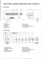
REARPANELCONNECTIONS/FRONT
PANELCONTROLS
REARPANEL
!'
94lr
?teP
./
'.:@,g) a_]li:gl
AMC
s*^" ^.,.'"*"-'6"a,50.
WELTRONICS
CORP.
1234
1 . C DI N P U T
2 . T U N E IRN P U T
3.VIDEO
INPUT
4 . L DI N P U T
5,TAPE1
IN/OUT
6,TAPE2IN/OUT
7.PREOUT/MAININ
TR
ERMINALS
S,LOUDSPEAKE
g,AC LINECORD
FRONTPANEL
l,POWERSWITCH
2 . I N F R A R ERDE C E I V E R
3.PHONES
4,BALANCE
CONTROL
5.DIRECT
SWITCH
6.BASSCONTROL
T.TREBtE
CONTROL
s.RECORD
SOURCE
SELECTOR
9,INPUT
SELECTOR
lO.VOLUME
CONTROL
J
REARPANELCONNECTIONS
CD INPUT
The CD input is suitablefor use with any CD
player.Connectyour CD playerto the amplifier
usingthe phonosocketsmarked"CD".
TUNERINPUT
The Tuner input is suitablefor use with most
AM/FMtuners.Connectyourtunerto the amplifier
usingthe phonosocketsmarked"TUNER".
VIDEO,LD
INPUTS
TheseVIDEO/LDinputsare suitablefor use with
the audio signalfrom a stereoVCR (or stereo
TV/Satellite/Cable
receiver)or other line level
source.Usingthe phono/phono
leadsconnectto
the "AudioOut"of the unitto theseinputs.
Note:Theseare audioinputsonly.
INPUT/OUTPUT
TAPEl,TAPE2
This inputis suitablefor use with mostcassette,
reelto reelor videorecorders.
Connectthe "record"leadsof yourtape recorder
to the ohonosocketsmarked"TAPEOUT"on the
rearof youramplifierusingphono/phono
leads.
Connectthe "playback"leads of your tape
recorderto the phonosocketsmarked'TAPElN'
on the rear of your amplifierusingphono/phono
PREOUT/MAININ
and power amplifier
Normallythe preamplifier
sectionsof this unit are connectedtogethervia
factory-installed
U-shapedmetal jumpers that
bridgethe PRE-OUTand MAIN-IN.jacks.
Check
to be sure that they are fully insertedinto the
jacksandthatnothingis touching
them.
By switching OFF the power and removingthe
metal jumpers, you can connect a signal
processorsuch as a surround-sound
decoderor
an electroniccrossoverin the oath between
preampand poweramp. connect a cablefrom
PRE-OUTto the processor's
inputand a second
cablefromthe processoisoutputto MAINlN.
LOUDSPEAKERS
Your AMC amplifieris designedto driveloudsoeakers
wrtha nominal
imoedance
of 4-8ohms.
LOUDSPEAKER
CONNECTIONS
The loudspeakeroutput terminalswill accept
4mm (banana)plugs, spade connectors,pin
connectors
or barewires.
Connectthe negativeside(usuallyblack)of your
lefthandloudspeaker
leadto the blackterminalof
the two terminalsmarked"L" on the rearof your
amplifier.
Theothersideof yourlefthandspeaker
(the
positive side or red) should be
lead
connected
to the red terminalmarked"L".Reoeat
thisoperation
for the righthandloudspeaker.
YourAMCamplifieris capableof generating
high
peak currents. so all connectionsmust be
checkedto avoidinadvertent
shortcircuitsand to
ensurea goodcleancontact.
UNDERNO CIRCUMSTANCES
SHOULDTHE
BE
OUTPUTS SHORTED
TOGETHER,
Such actionwill damageoutputcircuitryand is
notcoveredby guarantee.
AC LINECORD
PlugtheAC linecordintoa nearbywalloutletthat
provides
the correctAC powerlinevoltage,or into
an unswitchedconvenienceoutlet on anv AMC
products.
HEATSINK/VENTILATION
REQUIREM
ENTS
The heatproduced
by yourAMCamplifier
dunng
normal operationis dissipatedby an internal
finned heatsink.lt is perfectlynormalfor your
amplifierto becomesquitewarm and to radiate
heatwhenin use,especially
if it is run nearfull
power.However,if it becomestoo hot to touch,
switchoff at onceand contactyourdealer.
It is very importantthat there is adequate
ventilation
for the wholeof the amDlifier.
Do not
placethe uniton a rugor othersoft surfacethat it
couldsink into,obstructing
the air inlets on its
underside,
andtakecarenot to obstructthe outlet
grilleon thetop cover.
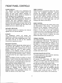
FRONTPANELCONTROLS
POWERSWITCH
The amplifierrs turned on by depressingthe
power switch. The small indicator above the
switch will glow green. Before switching on,
always set the volume control to minimum to
avoid damageto your loudspeakers.
Note:Your AMC amplifierwill play musicalmost
immediatelyafter being switchedon. However,in
common wrth other audiophile products, the
rnternalcircuitstake some time to stabilizefully,
and the best possiblesound qualitymay not be
obtaineduntil the amplifierhas had some time
(possiblyan hour or two) to warm up.
INFRAREDRECEIVER
The infrared receiver for receivingthe infra-red
srgnalsfrom your remotehandset.
PHONES
The headphone socket will accept any
headphonesfittedwith a standard1/4"(635mm)
stereojack plug.When Headphonesare in use,
the output will be cut and all the amp[fier
functionswill operateas normal.
BALANCECONTROL
The Balan:e Controladjuststhe relativelevelsof
the left and right channels.lt has no effect on
beingmade.A detentat the 12 o'clock
recordings
position marks the point of equal balance.
Rotation of the Balance Control to the right
(clockwise)decreases
the level of the left channel
so that only the rightchannelis heard. Rotation
to the left shifts the sonic image toward the left
soeaker.
Adjust the Balance Control to produce a natural
spread of sound across the space between the
with any monophonic
sound(suchas a
speakers,
radioannouncer's
voice)appearingas a phantom
imagecenteredmidwaybetweenthem.
Recordingsoften contain small errors in channel
balance,typicallyno more than 2dB; but this is
enough to degrade stereo imaging. Small
compensating changes in the setting of the
Balance Control can significantlyimprove the
depth and stabilityof the stereoimage.
DIRECTSWITCH
When this buttonis pressedthe Bass and Treble
circuits are completely bypassed, restoring
precisely flat frequency response. When this
button is pressedagain, the switch will be turned
off, the tone controls operate normally. By
adjusting the tone controls and then switching
them in and out of the signal path, you can
evaluatetheir effect on the sound.
BASS CONTROL
The Bass Controladjuststhe relatrvelevel of the
low frequenciesin the sound. The electrical
resoonseof the amolifieris flattestwhen the
controlis set in the detentor 12 o'clockposition.
Rotation of the knob to the right (clockwise)
increasesthe levelof low frequencysounds,and
decreasestheir level.
rotationcounter-clock-wise
Adjust the Bass Control to achieve the tonal
balancethat soundsmostnaturalto vou.
TREBLECONTROL
The TrebleControladjuststhe relativelevelof the
high frequenciesIn the sound. The responseof
the amplifieris flattestwhen the control is set in
the detent or 12 o'clock oosition. Rotationof the
Treble Control to the right (clockwise)increases
lhe levelof high frequencysounds,and rotation
decreases their level. Adjust
counter-clockwise
Treble Control to achieve the tonal balance
soundsmostnaturalto you.
RECORDSOURCESELECTOR
This switchselectsthe inputsignalfor recording.
(to TAPEOUTPUTSon rearpanel)
(1) TAPE RECORDING:
All sources CD, Tuner,Vrdeo,LD, Tapel and
Tape2can be recordedvia the tape connections.
To record an input, select the required source
and set your recorderto the recordmode.
To recordfrom one tape recorderto another,the
playbackrecordershould be plugged into the
'TAPE1 lN'socket, and the recordingmachine
into the 'TAPE2 OUT" socket. The RECORD
selectorswitch should be set to "TAPEl". A
recordingcan now be made in the normalway.
(2)TAPEPLAYBACK:
Set the input select switchto the "Tape1"(or
"Tape2")positronand set your recorderinto the
playback
mode.
INPUTSELECTION
The rotary input selectorswitch selectswhich
inputsignal(CD, Tuner,Video,LD, Tapel or
Tape2)is fed to the poweramplifier.
I
VOLUMECONTROL
The volumecontroladjuststhe overallloudness
levelof the sound.lt has no effecton the levelof
the signalsfed to the TAPEOUTjacks for tape
recording.The Volume controlis designedfor
accuratetrackingof its two channels,so that the
stereo balancewill not shift noticeablyas the
loudness
of thesoundis vaned.
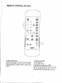
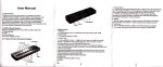
REMOTECONTROL(RC-001
)
aio@@
@
L
ffi
1. INPUTSELECTOR
Thesebuttonsselectany one of the six sources
that are connectedto the inputs of the AMC
3150a/3100a
(CD,TUNER,
TAPEI, TAPE2.LD&
vrDEo
)
@
2. MASTER
VOLUME
.^.:VOLUME
UP
v:VOLUMEDOWN
3. OTHERBUTTONS
Y1176@
Buttonson the RC-001remotecontrolthat
are not mentionedabove, are for use on
otherAMChighendAudiofuideo
products.
SPECIFICATIONS
3100a
R a t e dP o w eirn t o8 o h m . . . . . . . . . . . . . . .
Withbothchannelsdriven
R a t e dT . H . D2. O H z - 2 O K H 2 . . . . . . . . . . . .
. . . . . . . . .....1. .0 0 w
3150a
150W
0.037o
160W
Inputsensitivityfor lWRated Power into 8 ohms:
H i g hl e v e il n p u t s..... . . . .
..15mV/200mV
15mV/200mV
Inputimpedance:
20Kohms
H i g hl e v e li n p u t s . . . . . . . . . . . .
+/-O.2dB
+l-O.2dB
+r0 sdB
..................+/-0.5d8
<11HzJ>1DOKHz
..<1OHZJ>lOOKHZ
Signalto noiseratio(ref.1W8 ohms):
85dB
75dB
Highlevelinputs"A' WTD. .. ..
Separation
2OHz-2OKHz.....
Tonecontrolrange:
Bassat 100H2..
a t 1 0 K H z ........ . . .
Treble
+/-9dB
+/-9dB
+/-8dB
+/-8dB
OTHERS
(WxHxD)
Dimensions
N e tw e r 9 h t . ......
..
Shippingweight(2pieces)...
430x112x288mm
...10.8K9
...23.2K9
12.2Kg
26Kg
SAFETYINSTRUCTION
I. FEAO INSTRUCTIONS
Al tho safoty and oporating inskuclions should b€ road beforo th€
6pplianqais ope.alod.
2. RETAIN INSTRUCTIONS
Th. safoty and op€rating instructionsshould b€ retainedfor futur€
relerenca.
!5. SERV|CtNG
Th6 uso( 3hould not ansmpt to ssrvic€ tho 6pplianc. b€yond that
d6scribedin th€ gporatinginstructions.Allolho( saNicing should b€
rofe(6d lo Oualifiods€rvic! Osrsonngl
,I5. DAMAGEREOUIRINGSERVICE
Th6 spplianco shosld bs s6rvicad by qualiti6d ssrvrca personnel
3. HEEDYYARNINGS
Al waaningson thg appliancoand in the ope,atinginstruclions
should bo adhoredlo.
a) The power-supplycord or th6 plug has been damag€d; or
b) Obiocts hav6 lall6n, o. liquid has b66n spilled into the applianc.
ot
c) Th€ applianc€ has b9€n oxpos€d to rain; or
d) Th6 applianc€do€s nol appoar to oporats normally or .xhibit6 a
marked changg in p6rformanc€;oa
s) The appliancehas been dropped, or ihe 6nclosurodama96d.
4. FOLLOWINSTRUCTIONS
Aloperating and uso insvuctionsshould be lollowed.
5. WATER AND IiOISTURE
The appliancr should nol be us6d near water- tor examplo, noar a
bathlub,washbowl,kitchensink, laundry tub, in a w6i bas€m6nt,or
near a swimming pool, olc.
6. CARTS AND STANOS
Th6 applianc€ should b€ us€d only with a cart or stand that is
recommond6d
by ih6 manutacturer.
64.
A n a p p l i a n c ea n d c a r l c o m b r n a l i o n
shouldbe movod wrlh care Ourckslopg.
fOtC6,and UnOveOSudaCeS
6XC€SSIVo
m e y c a u s e l h 6 a p p l i a n c sa n d c a r t
combinationto overlurn.
7. WALLOR CEILINGMOUNTING
Thi6 oquipm€nt is not dssignad lo( uso mountod oo a wall or a
c.aling.
8. VENTILATION
Th6 applianc. should b6 situatodso that its locationor positiondogs
not interfsrawith its proper vontilation.Foa6xamplo,thg applianc6
shouldnot be situatodon a b6d, sola, aug,or similarsurlacgthat may
biockthe vonlilalionoponihgsior plac6din a built-ininslallalion,
such as bookc5seor cabinelihat may imp6de the llow ol air lhrough
lh6 ventilation
oponings.
9. HEAT
The applance should be situalod away lrom heal sourcessuch as
radialors,heat regislers,stoves,or other apphances(ihcluding
amDlifiers)lhal produceheat
I7. POWERLINES
(APPLIESTO TUNERAND RECEIVERS
ONLY)
An outdooaentgnna should bo localed awSyfrom powgr linas.
I8. OUTOOORANTENNAGROUNOING
(APPLIESTO TUNER AND NECEIVERSOI.ILY)
ll an outsidg antonna is conn6ctgd to tho rocriver, bo sur6 th6
antenna syst€m is groundod so as lo provid€ somg protection
againstvollago suroes and built up slalic chargos.
s€ction810 0l ih€ NarionalEloctricalcode, ANsl/NFPANo. 7s1984,
providos informationwith respeci to propgr grounding of th€ mast
and suppo.tingstructu16,grounding ollho l€ad-ine/irolo an antonna
d i s c h a r g 6 u n i t , s i 2 € o f 0 r o u n d i n g c o n d u c t o r g ,l o c 6 t i o n o l
antennaiischarg€ unit, @nnsclion lo grounding elgctrod6s,and
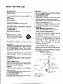
.€qukom€ntstor th€ grounding eloqlrode.Soe Figure.
a) Llsc No. 10 AWG (5.3 mm2) copp6r, tlo. I AWG (8.4mm2)
aluminum, No. 17 AWG (1.ornm') copper{lad gtgcl or bronz.
wk€, or largor,as a ground wko.
b) Socu.Ganlenna lcad-in lnd ground wirs3 to hous6 with 3tand{tl
insulalorsspacadl.om 6loet (1.22-1.83
m) apan.
c) Mountantenna
lead-in
dischergounitasclosoas possiblgtowhea€
entershous€.
d) Us€jumporr{ro nol smallorthan No 6 AwG {13.3mm?)coppor,
oatho oquivalent,whon a s€parateantenna4roundinOgleckod€
s used.SeeNECS€ction81S210)
Antenna GroundrngAccordlng to
t h e N a l r o n a l E l e c r f l c a lC o d e
I O.POWERSOURCES
The applianc€ should be connecled to a power supply only of the
typs describod in tho op€aalinginstruciionsor as ma.k€d on the
aootanc€.
r1, POWER.CORO
PROTECTION
PoweFsupplycords should b€ roulod so thal lhey are not likelyto b€
walkedon or pinchcd by iiems placrd upon or againstthem, paying
panicularatlonlionto cordsal plugs,comvonience
aeceptacles,
ahd
tho pointwhorethey €xittrom the applianco.
12. CLEANING
Tho appliancoshould be cleanedonty as recommendedby the
manulaclutel.
l!tc-
13. NON USEPERIODS
Thspower@rd of theappliancashouldbe unpluggedfromthe outl6t
wh€n lsft unus.d for a loog pcriod ol tim€
I4, OBJECTAND LIOUIDENTRY
Care should bo tak6n so thal objectsdo not lall and liquids are not
spilled into lho onclosursthrouqh op6nings.
!!'
o^.
a3!oo.!on
Er..r, rr
Cod?
la.(..Yh.rch
P.rl
S.cron 3to 2 il
WELTRONICS
CORP.
LONDON/I.A.