1
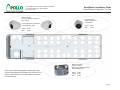
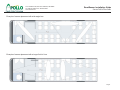
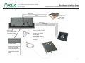
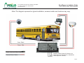
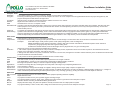
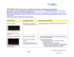
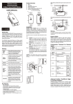
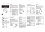
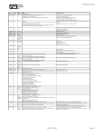
RoadRunner
Mobile Digital Video Recording System
Installation Guide - School Bus
Introduction
Cables and Hardware Description
Camera Placement
Camera Field-of-View
System Overview
Power Connections
Camera Wiring
External Recording Triggers
Laptop and IP Configurations
IRAS Software Installation
Glossary
Settings and Passwords
1331-118th Ave SE, Ste 300 - Bellevue, WA 98005
Tel: 800.641.1401
Fax: 425.453.0959
[email protected] www.avt-usa.com
1331-118th Ave SE, Ste 300 - Bellevue, WA 98005
Tel: 425.453.0430 / Fax: 425.453.0959
www.avt-usa.com
RoadRunner Installation Guide
Introduction
The Roadrunner is a Milspec-rated Digital Video Recorder for transit bus applications. It employs MPEG4 compression to record up to 4 cameras and 4 audio
sources on a removable hard drive, and can be accessed directly on board using a laptop computer, with the optional controller and monitor; or the removable
hard drive can be read directly on a desktop PC with the optional Hard Disk Player.
Installation follows these basic steps:
- Remove the DVR from its base and remove the cable guard from the rear of the DVR.
Note: be sure to pass the wiring through the cable guard if you wish to reinstall it when the wiring is complete.
- Mount the DVR base in its intended location (but DO NOT secure the DVR to its base until wiring is completed)
- Install the specified camera(s) in the front and rear of the bus
- Run the wiring through the bus, including the wiring for connecting the camera video, audio and power, and
Main Power connections using the supplied harness.
- If door-activated Event recording is needed, see instructions on page 7 of this guide.
- Connect the wiring to the rear panel of the DVR.
- Connect power and turn on the DVR.
If a laptop computer is being used to communicate with and program the Roadrunner:
- Assign the laptop an IP address which is compatible with the DVR’s IP address (see page 9).
- Install the IRAS software on the laptop
- Connect the Laptop to the DVR (see page 13).
- Refer to the direction in this guide for more data
If the optional monitor and controller are being used to communicate with the Roadrunner:
- Connect the monitor and controller as part of the installation (see page 5).
- Enter the menu by pressing the MENU button
- Enter the default password: 4321
- Refer to the operations manual for further instructions
Page 1
1331-118th Ave SE, Ste 300 - Bellevue, WA 98005
Tel: 425.453.0430 / Fax: 425.453.0959
www.avt-usa.com
RoadRunner Installation Guide
Cable and Hardware Descriptions
Note: These photos are for identification only. Some Items below are optional and may not be included with every
order. Other options may also be available. Individual specifications and color codes subject to change without notice.
RR-CT: Teardrop Vandal Resistant
Indoor/Outdoor Color Camera
Main Power harness: reduces 6 wires to 3;
connects to Ground, Battery and Ignition
Push Button Recording Trigger
RR-CD: Dome Vandal Resistant
Indoor/Outdoor Color Camera
Coax with BNC connectors at both ends.
Used for both video and audio sources.
Crossover network cable for laptop
installations (color may vary)
RR-CIR1: IR Illlumination Camera
with Audio Recording
Relay and pigtail: used to connect 12 VDC
sourcessuch as door switches to the alarm
inputs on the RoadRunner
RR-HDP: (Sold Seperately)
Hard Drive Player for connection to USB
compatible computer (also included: USB cable,
power supply, power cable)
Page 2
1331-118th Ave SE, Ste 300 - Bellevue, WA 98005
Tel: 425.453.0430 / Fax: 425.453.0959
www.avt-usa.com
RoadRunner Installation Guide
Camera Placement Suggestions: Top View
RR-CT Camera
Interior or Exterior Forward or
Rear Facing
RR-CD Camera
Fixed Ceiling Mount
or Wall Mount
Camera gimbal is reversible for
mounting at any angle
Yellow: Video
Red:
Power
Yellow: Video
Red:
Power
RR-CIR1 Camera
Interior, Infrared
Wide Angle, Reversible Image
Built-In Microphone
Note: Arrows indicate suggested mounting points only.
Actual camera placement will depend on the structure of
the bus, desired field-of-view, total number of cameras,
and other factors.
White: Audio
Yellow: Video
Red:
Power
Page 3
1331-118th Ave SE, Ste 300 - Bellevue, WA 98005
Tel: 425.453.0430 / Fax: 425.453.0959
www.avt-usa.com
RoadRunner Installation Guide
Camera Field of View Guide
Example of camera placement with wide-angle lens.
Example of camera placement with a longer field of view.
Page 4
1331-118th Ave SE, Ste 300 - Bellevue, WA 98005
Tel: 425.453.0430 / Fax: 425.453.0959
www.avt-usa.com
RoadRunner Installation Guide
System Overview- using Monitor and Control Panel to Control the DVR
Video-Coax
Audio-Coax
Power
Power - red
Audio - white
Video - yellow
Video-Coax
Audio-Coax
Power
Main Power:
Refer to Main Power
Connection Guide
Red + and black - power
wires to 12 VDC on DVR
Connect 9 pin cable to
RS-232 plug
Use supplied extension
cable to connect to
controller
Auxillary Power
Connections: 12 VDC
Output polarity sensitive
12V = Pos / G = Neg
Press tab, insert wire in
bottom hole. Test
connections by pulling
wire.
Page 5
1331-118th Ave SE, Ste 300 - Bellevue, WA 98005
Tel: 425.453.0430 / Fax: 425.453.0959
www.avt-usa.com
RoadRunner Installation Guide
Main Power Connections
Main Power Input
Red to Positive
Yellow to Ignition
If connecting to ignition switch,
use blue connector to tap
ignition wire.
CAUTION:
If connecting to fuse block,
connect ONLY to ignition fuse
Black to Negative
Install supplied
1 amp fuse
before ignition
switch
Red Power Wire
Install supplied
10 amp fuse
If available, use 24 VDC bus power (filtered on-board power not necessary)
Page 6
1331-118th Ave SE, Ste 300 - Bellevue, WA 98005
Tel: 425.453.0430 / Fax: 425.453.0959
www.avt-usa.com
RoadRunner Installation Guide
Camera Wiring: Power, Video and Audio
Note: This diagram represents a typical installation; camera models and locations may vary.
Coax - Black
Power - Red
Coax - Audio and Video Cables
Camera Power Cables
4 Auxillary Power Outputs for Cameras, etc.
4 Audio Inputs for External Mic or Camera Mic
4 Video Inputs for Cameras
Page 7
1331-118th Ave SE, Ste 300 - Bellevue, WA 98005
Tel: 425.453.0430 / Fax: 425.453.0959
www.avt-usa.com
RoadRunner Installation Guide
Connections: External Recording Triggers
It may be necessary or preferable to use switches, doors or other triggers to initiate recording.
READ THE FOLLOWING PRIOR TO INSTALLATION
Relay Connections:
STOP
Any 12 VDC or higher ouput MUST use
the supplied relay or damage to the DVR
can result.
Devices which go to Ground when
activated do not require the relay and
may be connected directly to the DVR
alarm inputs.
85
86
30
87
From 12 VDC trigger
To DVR alarm ground
Tied to 86
To DVR alarm input 1, 2 or 3
87
From 12 VDC output
85
86
30
To DVR alarm ground input
To DVR alarm input 1, 2 or 3
Many devices besides door switches or
indicators may be used as recording and
event log triggers.
Up to three external devices can be used
as Recording and Event log triggers.
Some software set-up is required; see
RoadRunner manual for more information.
Supplied Relays
and connectors
Alarm input 4 is reserved for the optional
Panic Button.
Page 8
1331-118th Ave SE, Ste 300 - Bellevue, WA 98005
Tel: 425.453.0430 / Fax: 425.453.0959
www.avt-usa.com
RoadRunner Installation Guide
Laptop Configuration: Step 1
Note: Roadrunner RAS Software is compatible with Windows 98, 2000 and XP. It is NOT compatible with Mac OS, Windows 95 or NT.
The Roadrunner DVR is generally preconfigured according to customer-supplied specifications before
delivery. However, should on-site programming be required, it is accomplished primarily with a laptop
computer and the supplied IRAS Software. This enables the user to create custom configurations,
multiple configurations for one DVR, or even to copy configurations into many DVR’s, which can be a
huge time savings when installing DVR’s into many vehicles.
Configuring a laptop to communicate with the Roadrunner DVR is not difficult and simply refers to
assigning the laptop an IP address that is compatible with the default IP address of the DVR. It is
similar to having two telephones… if they had the same phone number they would not be able to call
each other. In the same way, the laptop and the DVR must have different IP addresses.
The Roadrunner DVR has a factory default IP address of 192.168.1.129, which makes it simple to
connect to any MR4 you encounter in the field.
IP Address: (Internet Protocol) There are three parts to an IP address. Just like a phone number has
a country code, area code and exchange, i.e.: 01-555-555-5555, an IP address has the address, the
subnet mask and the gateway.
Generally it will only be necessary to set the laptop’s IP address and possibly the subnet mask:
192.168.1.130: IP address
255.255.255.0: Subnet mask
192.168.1.254: Gateway, if needed
1. First, go to the Start Menu, then click on Control Panel.
Page 9
1331-118th Ave SE, Ste 300 - Bellevue, WA 98005
Tel: 425.453.0430 / Fax: 425.453.0959
www.avt-usa.com
2.
On the Control Panel, select Network Connections, and either press the
ENTER key, or double-click with the mouse.
3.
On the Network Connections screen, select Local Area Connection,
then click the right hand button on the mouse and select Properties.
RoadRunner Installation Guide
Laptop Configuration: Step 2 & 3
Page 10
1331-118th Ave SE, Ste 300 - Bellevue, WA 98005
Tel: 425.453.0430 / Fax: 425.453.0959
www.avt-usa.com
4.
This opens the Local Area Connections Properties dialogue box,
now click on Properties
5.
In the properties window, scroll down in the white area to find Internet
Protocol (TCP/IP), then double click on it.
RoadRunner Installation Guide
Laptop Configuration: Step 4 & 5
Page 11
1331-118th Ave SE, Ste 300 - Bellevue, WA 98005
Tel: 425.453.0430 / Fax: 425.453.0959
www.avt-usa.com
6.
Select “Use the following IP Address”
For the IP Address, enter 192.168.1.130
If necessary, for the subnet mask enter 255.255.255.0
7.
Click the OK button to close this window. It may be necessary
to restart the laptop for this change to take effect. (restart not
necessary with Windows XP.)
8.
Install IRAS Software on laptop following the directions in the
supplied IRAS manual. Connect using the RoadRunner’s
default IP Address of 192.168.1.129.
RoadRunner Installation Guide
Laptop Configuration: Step 6,7 & 8
Page 12
1331-118th Ave SE, Ste 300 - Bellevue, WA 98005
Tel: 425.453.0430 / Fax: 425.453.0959
www.avt-usa.com
1.
Connect the ethernet cable
RoadRunner Installation Guide
IRAS Software Installation on Computer: Part 1
3.
Click on the small button with the
computer monitor on it at the
top left of the screen.
4.
Click on the Add button to open the
Add Site screen.
Color of the network, or ethernet,
cable may vary, but it must be a
crossover cable, and should be
labeled as such.
2.
After installing the sofware on laptop
or PC this Icon will appear on the
desktop. Double click it to open the
IRAS Admin Screen.
5. Assign a site name (usually the vehicle
number)
6. Enter the DVR’s default IP Address:192.168.1.129
7. Unit ID is not required.
8. Enter the default password: 12345678
9. Confirm the password.
10. Click the OK button to close the Add Site
screen.
11. Click the next OK button to close the
Setup-Admin screen.
Page 13
1331-118th Ave SE, Ste 300 - Bellevue, WA 98005
Tel: 425.453.0430 / Fax: 425.453.0959
www.avt-usa.com
RoadRunner Installation Guide
IRAS Software Installation on Computer: Part 2
To connect to the RoadRunner:
Click on the small + sign to drop down the Remote Site selection,
then double click on the site name.
OR
Click the connection button at the top of the screen.
Click on the butotn with the eye icon, to open the Watch
screen for live viewing.
Click the button with the magnifying glass icon to
open the Search screen for playback of recorded
video.
Refer to the supplied IRAS Software manual for further instructions.
Page 14
1331-118th Ave SE, Ste 300 - Bellevue, WA 98005
Tel: 425.453.0430 / Fax: 425.453.0959
www.avt-usa.com
RoadRunner Installation Guide
Glossary
Computer Terms
Bandwidth
The available capacity of a system or connection. Usually much less than the published rating.
Encryption
Processing and altering data so only the intended recipient can read or use it. The recipient of the encrypted data must have the proper decryption key and
program to decipher the data back to its original form.
IP Address
Internet Protocol. A series of numbers that sets the address of a device on a network.
Network
Digital connection between two or more devices.
HDD
Hard Disk Drive. Can be in a computer or DVR
RS-232/RS-422 Computer communication standards used in video for the control of certain video equipment. Computer controlled VCRs, edit controllers, switchers and other
studio equipment can commonly be found in professional video studios. Successfully linking two devices, at the very least requires that they use the same
communication protocol.
Serial Port
A computer l/O (input/output) port through which the computer communicates with the external world. The standard serial port uses RS-232 or RS-422* protocols
Watermarking
A pattern of bits inserted into a digital image, audio or video file that identifies the file's copyright information (author, rights, etc.) Unlike printed watermarks,
which are intended to be somewhat visible, digital watermarks are designed to be completely invisible, or in the case of audio clips, inaudible. Moreover, the
actual bits representing the watermark must be scattered throughout the file in such a way that they cannot be identified and manipulated.
Video Terms
Artifacts
Visible distortion or blurriness due to compression in images
Compression
The process of electronically processing a video picture to make it use less storage or to allow more video to be sent down a transmission channel.
Examples:
JPEG Still images, usually used for photos. Good quality but large files, short recording times.
MPEG Standardized motion-based compression, similar to that used on DVD’s and Cable TV broadcasts. Apollo’s chosen method of
compression, giving high quality video and longest recording times.
M-JPEG Non-standard method; series of still images with very large file sizes, very poor recording times.
ips
images per second. The rate cameras are sampled at for recording.
Resolution
1. The number of pixels (individual points of color) contained on a display monitor, expressed in terms of the number of pixels on the horizontal axis and the
number on the vertical axis. Examples: 720 x 288 or 352 x 240
2. Rating of the fine detail of a TV picture, measured in scan lines. The more lines, the higher the resolution and the better the picture. A standard VHS format VCR
produces 240 lines of horizontal resolution.
3. The process of removing picture data to decrease the size of a video image.
Camera Terms
AGC
Auto Gain Control. Circuitry in cameras that improves performance in low light conditions.
AWB
Auto White Balance. Circuitry in color cameras that compensates for different lighting conditions
BLC
Back Light Compensation. Ability of a camera to adjust for brightly lit backgrounds.
Digital Zoom
A method of zooming either by increasing the size of the pixels in the image or by interpolating between them.
Field Of View
Area covered by a camera
Optical Zoom
The use of lenses to change the focal length of a digital or analog camera. Image quality is superior to digital zoom.
White Balance
An electronic process used in camcorders* and video cameras* to calibrate the picture for accurate color display in different lighting conditions. (i.e., sunlight vs.
indoor incandescent) White balancing should be performed prior to any recording, typically by pointing the camera at a white object for reference.
DVR Terms
BNC connector A type of connector used on some VCRs, video and RF equipment providing twist-lock capability.
DVR
Digital Video Recorder
Event
Any input that creates an entry in a log and/or triggers recording to begin.
Input
Any signal received by a device. Audio, video, voltage and contact closure to ground are some examples of outputs.
Mil-spec
Rated for vibration according to established Military specifications
Monitor
Displays the video image, may also have speakers. Usually used when there is no laptop with the system
Output
Any signal created by a device. Audio, video, voltage and contact closure to ground are some examples of outputs.
Page 15
1331-118th Ave SE, Ste 300 - Bellevue, WA 98005
Tel: 425.453.0430 / Fax: 425.453.0959
www.avt-usa.com
RoadRunner Installation Guide
Settings and Passwords
Use this space to record your settings if changed from Defaults or Factory Presents.
Vehicle ID
________________________________
IP Address
_______ - _______ - _______ - _______
Passwords
Admin _____________________
User ______________________
Cameras
Cam 1 Title _____________________ Quality _____________________ Speed ____________
Audio _______________
Cam 2 Title _____________________ Quality _____________________ Speed ____________
Audio _______________
Cam 3 Title _____________________ Quality _____________________ Speed ____________
Audio _______________
Cam 4 Title _____________________ Quality _____________________ Speed ____________
Audio _______________
Alarms (Triggers)
Input 1 Name _______________________________
Input 2 Name _______________________________
Input 3 Name _______________________________
Input 4 RESERVED
Recording
Resolution
Timelapse Settings (non-event or alarm):
Quality ______________________
Speed __________________
Event Settings (triggered or alarm):
Quality ______________________
Speed __________________
Standard (up to 30 ips per camera) _________________
HDD: On Full Overwrite _______________
High (up to 15 ips per camera) _________________
Stop ________________
Other Notes:
Page 16