1
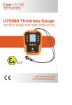
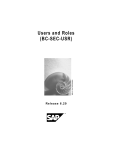
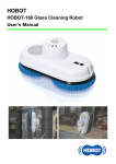
USER
MANUAL
UT5000
INTRINSICALLY SAFE
THICKNESS GAUGE
RUGGED AUTHORITY
www.cord-ex.com
Congratulations – You are the
owner of the next generation
ultrasonic thickness gauge
designed and certified
specifically for use in hazardous
(explosive) atmospheres.
UT5000 is certified ATEX/IECEx as follows:
•
Tested for Zone 1 IIC T4 hazardous areas
!
Please ensure that the
certification matches or
exceeds the hazardous area
characteristics that will be
clearly displayed on site.
!
Whilst in a hazardous area, do
not attempt to change batteries
or download images, these
tasks should only be undertaken
after returning to a safe area.
CONTENTS
Getting To Know Your UT5000
4
Overview
7
Package Contents
7
Getting Started
8
Registering Your UT5000
10
Taking Measurements
12
RIFD Tag Setup
16
Transducer Setup
17
Gauge Setup
18
Viewing Data
19
Using the Mini-app
20
Techincal Information
22
UT5000 – Intrinsically Safe Ultrasonic Thickness Gauge
GETTING TO KNOW
YOUR UT5000
3
2
1
3
2
7
1
4
4
5
1
Shock-resistant overboot
2
RFID Reader
3
Keypad buttons
RUGGED AUTHORITY
6
4
Probe
7
USB port
Desk stand
* Battery compartment
beneath deskstand and
shock resistant overboot.
Probe connectors
5
Power button
6
Calibration disc
1
4
Probe
2
3
RFID Reader
5
UT5000 – Intrinsically Safe Ultrasonic Thickness Gauge
OVERVIEW
1
1
RFID detect/ID
3
2
Measurement
2
4
3
5
The UT5000 measures material thickness
for Non-Invasive Testing (NIT) and Predictive
Maintenance (Pdm) on pipelines and fixed
equipment within hazardous locations.
UT5000 is a next-generation tester packed
with proven technologies:
• CorDEX CONNECT uses RFID + Software to
tag measurements with their location then
organizes the data, giving the engineer a
view of the pipeline at any specific location.
Battery level meter
4
Key function
• MultiECHO™ technology improves accuracy
on uneven surfaces; onboard memory stores
up to 1000 readings.
• Designed for rugged environments, the
shock-resistant skin protects the 3.1 inch
colour screen and has easy-to-feel, raised
buttons. The dual-element, 4MHz transducer
is adjustable up to 8Hz with accuracy of +/0.05mm.
• The unique corrosion mode option helps
identify spots of thinning.
5
Key
6
Power button
7
PACKAGE CONTENTS
Alarm min/max values
8
Settings: Pulse rate Material Velocity
Carefully unpack your UT5000 Intrinsically
Safe Thickness Gauge and ensure that you
have the following items:
• UT5000 Intrinsically Safe Thickness Gauge
• Hard Carry Case
6
Focus Ring
RUGGED AUTHORITY
8
7
• 1 x Probe
• USB Communication Cable
• Couplant Gel
• Battery
• Wrist Strap
• RFID tags
135˚ Swivel Lens
7
UT5000 – Intrinsically Safe Ultrasonic Thickness Gauge
GETTING STARTED
Inserting The Battery
The battery compartment is in the rear of the
instrument under the orange shockresistant
overboot.
WARNING! Use only a Tadiran 3.6V Lithium
Thionyl Chloride Cell (19.0Ah, SL-2780/S,
CorDEX Part No: CDX5000-327). The use of
any other type of battery is strictly forbidden!
To change the battery:
1
Remove the orange shock-resistant overboot
by stretching it over the lower corners of the
unit at the front. It may help to remove the
stand from the back and to open the USB and
probe connector covers.
2
Half turn the two screws on the compartment
cover and then carefully lift off the cover.
3
When exchanging the battery, the memorized
parameter and calibration values are deleted.
Therefore, you need to execute a new
calibration and enter the relevant parameters
again after exchange of the batteries.
After battery replacement, switch the
instrument on/off twice to reset it to a
predefined operating status. All previous
settings will be restored to the tester after
connecting to the CorDEX CONNECT™
software, or the UT5000 Mini app.
Connecting the Probe
Calibration/ Zeroing
WARNING! Only approved transducer ( CorDEX
part no: ExTC4/10) with approved cable
( CorDEX part no: CDX5000-221) can be
operated in ATEX zone environments.
The UT5000 has a calibration disc mounted on
the front of the unit. To calibrate the probe:
Press the probe plugs (it does not matter
which way round the connectors are fitted)
into the connector sockets on the rear of the
UT5000.
Turning the Power On/Off
!
Always use with outer orange
overboot fitted and never
open the battery or USB
compartments in a hazardous
environment.
To switch the UT5000 on or off, press the
Power button and hold it down for about 5
seconds. The UT5000 has an AUTO SLEEP
feature: it turns off automatically when the
device has not been operated for a fixed
period of time (see page 18). To resume the
operation condition, press any button.
1.Apply a drop of the supplied couplant (see
page 12) to the disk or the probe.
2.Press the probe onto the disc and hold it
firmly.
3.Press the SETUP key.
4.Use the arrow keys to highlight Transducer
Setup ; then press the SEL key.
5.Use the arrow keys to highlight Probe zero
built in ; press the SEL key.
6.After the UT5000 has taken several
measurements, press the SEL key.
The unit is now zeroed and ready for use.
Make sure that the rubber sealing of the cover
is not damaged or removed from the guiding
notch.
4
Insert the battery.
WARNING! - Ensure correct orientation
according to the sketch on the battery cover
to avoid internal damage.
RUGGED AUTHORITY
9
UT5000 – Intrinsically Safe Ultrasonic Thickness Gauge
REGISTERING YOUR
UT5000
Connecting The UT5000
Registration
Using the supplied USB cable, connect the
UT5000 to a PC with a working internet
connection. Windows will detect the
connection and display the Found New
Hardware prompt. Allow Windows to search
for the appropriate device driver.
The UT5000 Mini App starts automatically and
prompts you to enter your registration details.
You will need to enter the serial number for
your unit. This is shown on the rating plate on
the back of the unit. You can also display the
serial number on screen:
1.Press the VIEW button on your UT5000.
Installing the UT5000 Mini-App
You can install the UT5000 Mini App from the
supplied CD or by downloading it from the
CorDEX Instruments website.
Load the CD into your PC and follow the onscreen instructions.
Alternatively, download the Mini App from:
http://miniapps.cordexinstruments.com/
UT5000/
Click on the DOWNLOAD SOFTWARE button to
proceed.
The Mini App requires Windows Installer
3.1 and .NET Framework 3.5 SP1. These
may already be present on your PC but, if
not, the installer will download and install
the necessary files automatically. This is,
however, a 197MB download so it may take
some time, depending on your connection
speed. Alternatively, you can install the files
from the supplied CD.
RUGGED AUTHORITY
2.Press the down arrow to highlight the ABOUT
option.
3.Press the SEL button.
Complete the registration form and then click
on the Activate button. Registration may
take a few seconds to complete. Following
registration, you will have full access to the
application to download data, upload material
and gauge settings and RFID information.
Following installation, you will be able to start
the application in future from the Start menu:
select All Programs > CorDEX Instruments >
UT5000.
11
UT5000 – Intrinsically Safe Ultrasonic Thickness Gauge
TAKING
MEASUREMENTS
Using the Probe
Measurement Modes
Setting the Mode
The probe face is split into two halves: one
half transmits ultrasonic sound waves and the
other half, separated across the centre by a
barrier, receives any reflected signals.
The UT5000 supports two types of
measurement:
The pulse frequency determines the rate of
repeated measurements. To change the pulse
frequency:
The probe measures the thickness of the
material directly beneath the probe face.
The accuracy of the measurements depend
on good contact with the target material. In
particular, you must ensure that there are no
air gaps or pockets between the material and
the probe face. To achieve a good contact,
apply a droplet of the couplant gel to the
target area and press the probe firmly onto it.
Continue to apply gentle downward pressure
to the probe during the measurements.
Sometimes it can be difficult to obtain good
contact with the target material. Be aware
that layers of paint or rust can interfere with
the transmission of the ultrasound.
Single Measurement Mode
The gauge stores a single spot thickness.
This is important when inspecting pipeline
thickness in a specific location. You can
configure single mode measurements to
include up to four consecutive Txpulse
measurements using the Multi-Echo setting
(see page 13). The default is one Txpulse
measurement.
Continuous Measurement
(Corrosion) Mode
In this mode, the gauge continues to take
measurements at the specified pulse
Frequency until the STOP key is pressed. The
UT5000 averages all valid measurements
while in this mode storing maximum, minimum
and average values.
Press the FREQ key, or Press the SETUP
key. Use the arrow keys to highlight Pulse
Frequency, then press the SEL key.
For single measurements, choose Single shot.
For continuous measurements, choose from
the following options: 1, 2, 3, 4, 5, 6, 7 or 8 Hz.
Measurements will be taken continuously at
the selected rate and continue until the STOP
key is pressed.
Use this mode for basic corrosion inspection:
move the probe slowly over a 100mm square
area and monitor the maximum and minimum
thickness in the inspected area, along with
the average thickness measured.
RUGGED AUTHORITY
13
UT5000 – Intrinsically Safe Ultrasonic Thickness Gauge
Selecting Material Velocity
To carry out an accurate measurement, it is
important that you provide the UT5000 with
the correct velocity of sound in the medium
to be measured. The UT5000 contains a table
of values for the most common materials.
For more unusual materials, you may need to
enter the velocity manually.
To change the current material velocity, press
the VEL key on the main display.
Use the UP or DOWN keys to choose from the
following options:
Material User Defined
Use this option to enter material velocity data.
CAUTION! For user defined data, you are
overriding any safety checks within the gauge.
If you attempt to override a preloaded material
velocity value, the UT5000 prompts you to
confirm any changes: “Material velocity data
mismatch, continue YES/NO”.
To define a new material:
1.Select UD Material Text.
Taking a Measurement
Before you take a measurement check that
you have:
• Fitted the probe (see page 9)
• Applied couplant to the target area (see
page 12).
• Chosen the correct material velocity (see
page 14).
• Material From List
• Use the arrow keys to highlight the required
character, then press the SEL key.
• Zeroed/calibrated the gauge (see page 9).
Having made your choice, press the SEL
button to continue.
• Repeat this procedure until you have entered
the full text.
3.Use the arrow keys to highlight ACCEPT, then
press the SEL key.
Material From List
This option allows you to select a velocity
from the UT5000’s internal table of predefined
materials (see page 10). You can add
materials to the velocity data table using the
host system (UT5000 Mini-App).
To select a new material, use the arrow keys
to highlight the required material, then press
the SEL key. The new material and velocity
replaces the current selection and, until the
material is changed, all measurements are
calculated using the user-defined velocity
value.
RUGGED AUTHORITY
4.Select UD Material Velocity.
5.Enter the velocity for the material:
• Use the arrow keys to highlight the required
digit, then press the SEL key.
• Repeat this procedure until you have entered
the full value.
6.Use the arrow keys to highlight ACCEPT, then
press the SEL key.
The new material and velocity replaces the
current selection and, until the material is
changed, all measurements are calculated
using the user-defined velocity value.
If you want to store the measured values,
press the SAVE key. To download all saved
measurements to a PC, see page 19.
• Selected the required measurement mode
(see page 13).
2.Enter the name of the material you want to
define:
• Material User Defined
3.Press the STOP key to stop measuring. If any
of the measurements exceed the defined
alarm settings for the RFID tag location, the
corresponding alarm setting is displayed
with red text.
To take the measurement:
If an RFID tag applies to the target area, press
the SCAN button. The unit must be within 5cm
of the tag for reliable detection. If a tag is
detected, all subsequent measurements will
be associated with the tag. If you have set
up the tag with material and alarm settings,
these are displayed by the UT5000.
1.Press the probe onto the target area,
attempting to exclude all air at the contact
point.
2.Holding the probe firmly, press the
UT5000’s MEAS key. If you have selected a
pulse frequency, the UT5000 displays the
maximum and minimum values obtained so
far, and the average measurement.
15
UT5000 – Intrinsically Safe Ultrasonic Thickness Gauge
RIFD TAG SETUP
TRANSDUCER
SETUP
Detecting a Tag
Setup Alarms
Pulse Frequency
Choose from the following options:
To carry out an accurate measurement, it is
important that you provide the UT5000 with
the correct velocity of sound in the medium
to be measured. The UT5000 contains a table
of values for the most common materials.
For more unusual materials, you may need to
enter the velocity manually.
Set the low and high alarms for thickness
measurements within the vicinity of this RFID
Tag.
The pulse frequency determines the rate of
repeated measurements. To change the pulse
frequency:
• Off
To set an alarm, highlight the Low or High
alarm option, then press the SEL key. Use the
arrow keys to highlight the required digit, then
press the SEL key. Repeat this procedure until
you have entered the full value. Use the arrow
keys to highlight ACCEPT, then press the SEL
key.
• Press the FREQ key, or
Tag Alias
Use the on-screen keyboard to define the
name of the RFID Tag. Use the arrow keys to
highlight the required character, then press
the SEL key. Repeat this procedure until you
have entered the full name. Use the arrow
keys to highlight ACCEPT, then press the SEL
key.
The ALARM key on the main display provides a
shortcut to this menu option.
You can also set up RFID tag information
through the UT5000 mini app (see page 11).
• Press the SETUP key. Use the arrow keys to
highlight Pulse Frequency, then press the
SEL key
Choose from the following options:
• Single shot
• The UT5000 takes one measurement
• 2,3 or 4
Use the arrow keys to highlight the required
option then press the SEL key.
Probe Zero Built In
Select this option to calibrate/zero the probe
using the UT5000’s built-in calibration disc
(see page 9).
• 1, 2, 3, 4, 5, 6, 7 or 8 Hz
• Measurements are taken continuously at the
selected rate and continue until the STOP
key is pressed
Material Velocity
Transducer Select
Select a predefined material and velocity from
the UT5000’s internal table or define your
own. The value will be assigned to the RFID
Tag. This procedure has been described on
page 14.
Identify the type of transducer probe, e.g.
4MHz transducer.
Probe Zero/Cal Double
Select this option to calibrate/zero the probe
using the UT5000’s built-in calibration disc
(see page 9).
Measure Material Velocity
Select this option to estimate the material
velocity for a sample of known thickness.
Multi Echo
The Multi Echo option allows averaging of
individual measurements for greater accuracy
on uneven surfaces.
RUGGED AUTHORITY
17
UT5000 – Intrinsically Safe Ultrasonic Thickness Gauge
GAUGE SETUP
To display the Gauge Setup menu, press
SETUP. Then, use the arrow keys to highlight
Gauge Setup and press the SEL key.
Choose from the following options:
• Date Format
VIEWING DATA
Sleep Timer
To save power, the UT5000 will switch off
after the specified period of inactivity. Choose
the time period: 1min, 2min, 3min, 4min or
5min.
• Sleep Timer
• Units
• Handedness
Choose whether the UT5000 uses and
displays metric or imperial units.
Choose from the following formats:
• YYYY/MM/DD
• MM/DD/YYYY
• MM/DD/YYYY
The time and date are updated automatically
whenever you connect to the UT5000 mini
app, CorDEX CONNECT or to CorDEX CAMS.
Time and Date cannot be set manually.
Choose whether the main functions of the
UT5000 use the buttons on the left or right
side. The “handedness” setting refers to the
hand used by the operator to hold the device.
For example, if the operator holds the device
in their right hand, a ‘right’ handedness
setting ensures that the main functions of the
UT5000 are operated by buttons on the left
side of the unit.
You can also set the Date Format and Sleep
Timer using the UT5000 mini app.
Reset Basic Gauge Setup
Select this option to restore the factory default
gauge settings, for example, Pulse Frequency.
Tag and material information is not affected.
• Stored Measurements
Stored Measurements
Data is listed for each registered RFID Tag in
the following format:
Handedness
Date Format
Choose from the following options:
• Reset Basic Gauge Setup
Units
Use the arrow keys to highlight the required
option, then press the SEL key.
To view stored data, press the VIEW key on
the main display. Select STORED DATA, then
press the SEL key.
!
Never open the battery or USB
compartments in a hazardous
environment.
• RFID Tag
• Tag Alias
• Material, source and name, e.g. From List:
Alumin
• Vel: Material velocity
• Min: Minimum measurement
• Max: Maximum measurement
• Mea: Average measured value
• Date: date of last measurement
• Time: time of last measurement
Use the up and down arrow keys to scroll
through saved measurements.
RUGGED AUTHORITY
19
UT5000 – Intrinsically Safe Ultrasonic Thickness Gauge
USING THE MINI-APP
Starting the Mini-app
Adding/Editing/Deleting Tags
Get/Clear Readings
Connect your PC to the gauge using the
supplied cable. Run the UT5000 miniapp by
choosing:
• To add a new material, type its Name, enter
a Velocity (m/s) and then click on the Add/
Edit button.
To download all saved readings in CSV file
format:
Start > All Programs > CorDEX Instruments >
UT5000
• To edit an existing material, select it in the
list and click on the Edit button. Change the
RFID Alias and Alarm Settings as required.
To apply a material to the tag, select it in
the Materials list and then click on the Grab
button.
The following functions are accessed in the
USB mode:
• Adding/editing material velocity information
• Adding/editing RFID tag information
• To delete an existing material, select it in the
list and click on the Delete button.
• Editing gauge settings (date format and
sleep timer period)
• Download saved measurements
Adding/Editing/Deleting Materials
• To add a new material, type its Name, enter
a Velocity (m/s) and then click on the Add/
Edit button.
• To edit the information for an existing
material, select it in the list and then change
the name and velocity as required. Click on
the Add/Edit button.
• To delete an existing material, select it in the
list and click on the Delete button.
RUGGED AUTHORITY
Gauge Setup
You can use the Mini App to change the Date
Format and to set the Sleep Time. You can
also edit these parameters through the Setup
menu (see page 14).
Date Format
Choose from the following Date Formats:
DD/MM/YYYY
MM/DD/YYYY
YYYY/MM/DD
1.Click on the Get Readings button. Readings
are stored in the
My Documents > CorDEX Instruments > UT
Gauge data files folder.
2.Choose whether you want to clear the
entries from the gauge.
If you have enabled the appropriate options in
Windows, the data file is automatically opened
in the PC’s default application for viewing csv
files. To view the settings on your PC:
• Open Windows Explorer and select:
Tools > Folder Options > File Types.
• Scroll down to and select CSV.
• Click on the Change button to associate an
application with CSV files and choose how
the file opens.
To clear readings from the gauge without
downloading, click on the Clear Readings
button.
Sleep Timer
To save power, the UT5000 will switch off
after the specified period of inactivity. Choose
the time period: 1, 2, 3, 4 or 5 minutes.
21
UT5000 – Intrinsically Safe Ultrasonic Thickness Gauge
Specification
Certification
Tested for Zone 1 IIC T4 hazardous areas
No hot work permit necessary
Memory
Stores up to 1000 measurements
Screen
3.1” RGB TFT colour screen with backlight
Right/left handed set up
Material Velocity Selection
Preloaded via Drop-Down menu, or user defined.
Transducer
Dual Element
Pulse Rate
Standard transmit pulse rate of 4Hz Adjustable from single shot up to
8Hz
Receiver Bandwidth
1MHz to 15MHz (-3dB points)
Frequency
4MHz, 3mm up to 100mm
Accuracy
+/- 0.05mm
RFID Tag Reader
• Operates with 13.54MHz passive tags
• Detection range up to 5cm
• Supports ISO/IEC 15693-2, ISO/IEC 18000-3 tag formats
Battery Details
• 3.6V Lithium Thionyl Chloride Cell (19.0Ah, SL-2780/S, Farnell Part
No: 118-7256)
• 100 hours continuous operation with back light restrictions
• Low battery warning
Operating Temperature
-10 to +50°C
Interface
USB connector
Dimensions (excluding battery)
160mm (W) x 215mm (H) x 63mm (D)
Weight
930g (without probe)
RUGGED AUTHORITY
23
Copyright © 2014, CorDEX Instruments Limited.
All other brand and product names are
trademarks of CorDEX Instruments Limited.
Ref. ID 5001, Rev. A