1
USER
MANUAL
V e r 1,0
WWW.BRITEQ-LIGHTING.COM
1
PRODUCT (GENERAL)
1.1
PRODUCT INTRODUCTION
This product is designed for indoor or outdoor use. Suitable applications include wash or
effect lighting for architectural, stage or nightclub applications. This product can also be
installed for use in signage and advertising using the dynamic functions available with
DMX512 control. Direct input of DMX512 signal allows the units to be controlled from any
DMX512 controller. This product can be operated as a single unit or in multiple units for
large applications.
The specially developed controller that allows the product to be controlled independent of
the DMX512 controller enables the user to create and edit a wide range of custom programs.
All programs can be touch-button displayed or scheduled to START and END at scheduled
times. When programs have been created or edited in the controller, it is also possible to
trigger these programs using the DMX IN function when connected to a DMX512 controller.
1.2
PRODUCT FEATURES
LED FIXTURE
* RGB Dimmer 0-100%
* Strobe
* Individual control of each LED group
* Automatic programs
* IP65 protection rating
* LCD display
* Display control 'lock-out'
* Direct DMX512 input
* Automatic DMX512 and ID Addressing
* Independant ID address
* Overheat protection (showing "warning heat")
* Lightweight aluminium casing
* Black anti-UV plastic cover
* Interlocking-module system
1 PRODUCT(GENERAL)
1
2008.8.13
1.3
TECHNICAL SPECIFICATIONS
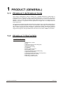
LED MODULE
LED MODULE:
Voltage
100~240V...50/60Hz
Rated Power
150W
IP65 protection rating
IP
108pcs (36 x RED / 36 x GREEN / 36 x BLUE)
LED/Unit
Output/LED
1W
Cooling
Direct air convection
Dimensions
570 x 220 x 190mm
Weight
1 PRODUCT(GENERAL)
13Kg
2
2008.8.13
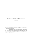
1.4
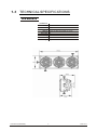
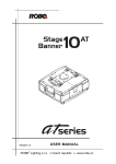
PHOTOMETRIC DATA
PHOTOMETRIC DATA
RGB 100%
9100
2910
1370
800
2(0.9x0.5)
4(1.4x1.0)
6(2.0x1.6)
8(2.5x2.1)
8100
2570
1160
689
2(0.9x0.5)
4(1.4x1.0)
6(2.0x1.6)
8(2.5x2.1)
2900
893
414
238
2(0.9x0.5)
4(1.4x1.0)
6(2.0x1.6)
8(2.5x2.1)
5565
1752
836
471
2(0.9x0.5)
4(1.4x1.0)
6(2.0x1.6)
8(2.5x2.1)
710
231
110
64
2(0.9x0.5)
4(1.4x1.0)
6(2.0x1.6)
8(2.5x2.1)
643 LUX
15
3
2
1
0
1
2
3
10(3.0x2.6Area(m))
Diameter(m)
WHITE
575 LUX
15
3
2
1
0
1
2
3
10(3.0x2.6Area(m))
Diameter(m)
RED
197 LUX
15
3
2
1
0
1
2
3
10(3.0x2.6Area(m))
Diameter(m)
GREEN
396 LUX
15
3
2
1
0
1
2
3
10(3.0x2.6Area(m))
Diameter(m)
BLUE
1 PRODUCT(GENERAL)
53 LUX
15
3
2
1
0
1
2
3
3
10(3.0x2.6Area(m))
Diameter(m)
2008.8.13
1.5
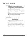
SAFETY WARNING
IMPORTANT
ALWAYS READ THE USER MANUAL BEFORE OPERATION.
PLEASE CONFIRM THAT THE POWER SUPPLY STATED ON THE
PRODUCT IS THE SAME AS THE MAINS POWER SUPPLY IN YOUR
AREA.
This product must be installed by a qualified professional.
Always operate the equipment as described in the user manual.
A minimum distance of 0.5m must be maintained between the equipment and
combustible surface.
The product must always be placed in a well ventilated area.
Always make sure that the equipment is installed securely.
DO NOT stand close to the equipment and stare directly into the LED light
source.
Always disconnect the power supply before attempting and maintenance.
Always make sure that the supporting structure is solid and can support the
combined weight of the products.
The earth wire must always be connected to the ground.
Do not touch the power cables if your hands are wet.
ATTENTION
This product left the place of manufacture in perfect condition. In order to
maintain this condition and for safe operation, the user must always follow the
instructions and safety warnings described in this user manual.
Avoid shaking or strong impacts to any part of the equipment.
Make sure that all parts of the equipment are kept clean and free of dust.
Always make sure that the power connections are connected correct and
secure.
If there is any malfunction of the equipment, contact your distributor
immediately.
When transferring the product, it is advisable to use the original packaging in
which the product left the factory.
Shields, lenses or ultraviolet screens shall be changed if they have become
damaged to such an extent that their effectiveness is impaired.
The lamp (LED) shall be changed if it has become damaged or thermally
deformed.
1 PRODUCT(GENERAL)
4
2008.8.13
2
2.1
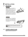
INSTALLATION
MOUNTING
HANGING
The LED MODULE can be mounted in a
hanging position using the support frame. It is
possible to use any bolt of the correct size and
strength to mount the fixture.
It is
recommended to use at least 2 mounting points
per fixture. Mounting with a clamp or other
mounting bracket is recommended depending
on the requirements of your application.
For overhead use, always install a securechain that can hold at least 10 times the weight
of the fixture. You must only use safety-ropes
with screw-on carabines. Pull the safety-rope
through the aperture on the the base's metal
frame. Insert the end in the carabine and
tighten the fixation screw. (See picture on right)
UPRIGHT
The LED MODULE can be mounted upright
using the support frame. It is possible to use
any bolt of the correct size and strength to
mount the fixture. It is recommended to use at
least 2 mounting points per fixture. Mounting
with a clamp or other mounting bracket is
recommended depending on the requirements
of your application.
UPRIGHT
The LED MODULE can be mounted at any angle and in any
position. It is possible to further adjust the angle of the LED
MODULE using the two adjustment knobs located on the side of
the fixture.
2.2
POWER CONNECTIONS
@ 220~240V: 15 units may be connected in series
@100~120V: 8 units may be connected in series
2 INSTALLATION
5
2008.8.13
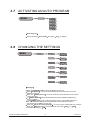
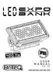
2.3
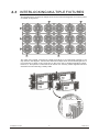
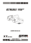
INTERLOCKING MULTIPLE FIXTURES
The diagram above shows how multiple units can be interlocked together to create a 'panel'
or 'blinder' arrangement.
The 'male' and 'female' connections enable the fixtures to be interlocked together in the
way shown in the diagram. Please note that when multiple units are mounted together it is
not necessary to attach every single unit to the truss, wall or weight supporting system.
However, it is important to ensure that all fixtures are securely locked together and that
each fixture is secured using a safety cable.
2 INSTALLATION
6
2008.8.13
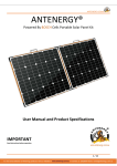
2.4
SETTING UP WITH A DMX512
CONTROLLER
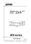
2.4-1 DMX512 ADDRESSING WITHOUT ID ADDRESSING
(STAGE 1 MODE)
Connect the DMX512 controller to the units in series.
Each unit has 12 DMX channels so the DMX Addresses should increase by increments of
12 (e.g. 1,13,25,37...)
The ID address has not been set so therefore when using the controller CH10 must
be inactive ( CH10=0 ).
It is also possible to deactivate ID address selecting ID OFF from the Settings menu.
on the fixture
Each DMX Address may be used as many times as required.
Any DMX address in the range from 001 to 245 may be used.
Example:
DMX Addr.1
DMX Addr.13
DMX Addr.25
............
DMX512
CONTROLLER
The figure above shows a simple DMX512
layout with the starting address of the first
unit set at 1, with the second set at 13 and
so on... (Note that when used in this way,
the CH10 ID function must be inactive (CH10=0))
2.4-2 DMX512 ADDRESSING WITH ID ADDRESS(STAGE 1 MODE)
Connect the DMX512 controller to the units in series
Each unit has 12 DMX channels so the DMX Addresses should increase by increments of
12 (e.g. 1,13,25,37...)
Each DMX Address may be used as many times as required.
Any DMX address in the range from 001 to 245 may be used.
Each DMX address may carry up to 66 separate ID addresses.
ID Address should be set in the Settings menu on each unit in ascending values
(i.e. 1,2,3...)
ID On should be set in the Settings menu on each unit.
ID addresses are accessible from CH10 on the DMX512 controller.
2 INSTALLATION
7
2008.8.13
Example:
DMX Addr.1
ID Addr.1
DMX Addr.1
ID Addr.2
DMX Addr.1
ID Addr.3
DMX Addr.13
ID Addr.1
DMX Addr.13
ID Addr.2
DMX Addr.13
ID Addr.3
............
DMX512
CONTROLLER
The figure above shows a simple DMX layout
which has used three units at each DMX address.
The three units have different ID addresses which
allows the user to collectively control the whole
group of units at that DMX address by setting
CH10 to 0, or to control each unit independently by
first selecting the DMX address and then by using
CH10 to locate the target ID address. (Note that
when using ID addresses it is also possible to
activate ADAS which allows for even more options
with DMX addressing and control see ADAS
Addressing section 2.2-3)
2.4-3 ADAS WITH ID ADDRESS(STAGE 1 MODE)
Connect the DMX512 controller to the units in series
Select ADAS ON from the Settings menu
ID Address should be set in the Settings menu on each unit
in ascending values (i.e. 1,2,3...)
ADAS addressing is based on the ID address as follows:
ADAS DMX Address = { ADAS fader * (ID Address -1)}+ 1
ADAS addressing is activated by moving CH8 + CH10 faders to the 255 value (CH8 = 255 &
CH10 = 255)
ADAS addressing is deactivated by moving CH8 + CH10 + CH11 to the 255 value
(CH8 = 255, CH10 = 255 & CH11 = 255)
When ADAS is deactivated, all DMX addresses will return to their original DMX Address.
To permanently store ADAS DMX addresses, select ADAS copy from the Settings
menu,on the target fixtures to store the new DMX Address.
Example:
ID Addr.1
ID Addr.2
ID Addr.3
............
The figure above shows a simple ID address
layout using one DMX address. Each of the
units has a different ID address which will
receive a new temporary DMX address when
ADAS is activated (unless ADAS copy
is selected). The user is able to activate and
deactivate ADAS at will giving the possibility
of creating many different fixture grouping
possibilities using the ID address, real DMX
address and the ADAS temporary DMX address.
DMX512
CONTROLLER
Note:
When using ADAS, all fixtures must have the
following settings from the Settings menu set correctly;
ID address
ID ON/OFF
ADAS fader no
ADAS ON/OFF
2 INSTALLATION
Each unit should have the target ID address set in ascending order
Each unit should set ID On
Each unit should be set to the same number of faders as your
controller(must be 12)
Each unit should be set as ADAS On
8
2008.8.13
3
3.1
DISPLAY PANEL OPERATION
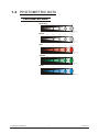
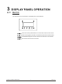
BASIC
The LED fixture is mounted with a LCD display and 4 control buttons.
SET
UP
DOWN
EXIT
enter the currently selected menu or confirm the current function value
scroll 'UP' through the menu list or increase the value of the current function
scroll 'DOWN' through the menu list or decrease the value of the current function
exit from the current menu or function
3 DISPLAY PANEL OPERATION
9
2008.8.13
3.2
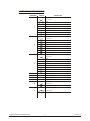
MENU
MENU
Dimmer
Red
Green
Blue
Color macros
Strobe
Dimmer
Red
Green
Blue
Color macros
Strobe
0
0
255
255
0
255
0
0
0
255
255
255
DMX512
Address
Address
1
512
Personality
STAGE 1
STAGE 2
Static color
PIXEL
ARC 1
ARC 1+D
Run mode
DMX
CON
Auto program
Auto
Auto
Auto
Auto
Auto
Auto
Auto
Auto
Settings
ID address
ID address
001
066
ID ON/OFF
ID
ON/OFF
ADAS fader no
ADAS fader no
01
244
ADAS ON/OFF
ADAS
ON/OFF
ADAS copy
ADAS copy
ON/OFF
R e s e t to
Factory settings
Reset confirm
Dimmer start
Dimmer start
001 / 005
Password ON/OFF
Password
ON/OFF
Set password
Set Password
Password
3 DISPLAY PANEL OPERATION
10
1
2
3
4
5
6
7
8
2008.8.13
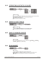
3.3
CREATING A STATIC COLOR
MENU
Dimmer
Red
Green
Blue
Color macros
Strobe
Static color
Dimmer
Red
Green
Blue
Color macros
Strobe
0
0
255
255
0
255
0
0
0
255
255
255
Static colour
Combine RED, GREEN and BLUE to create an infinite range of colors (0-255)
Enter Color macros
allow to choose 18 color macros
Set value of dimmer (0-255)
Set the value of the strobe (0-20Hz)
3.4
DMX512 SETTINGS
MENU
Address
DMX512
1
512
DMX512 address
Enter the DMX address mode to set the DMX address
Activate control from outside source by activating ON
3.5
DMX CHANNEL MODE
MENU
Personality
STAGE 1
STAGE 2
PIXEL
ARC 1
ARC 1+D
Personality
Enter Personality mode to choose DMX mode:
PIXEL , ARC 1 or ARC 1+D .
3.6
STAGE 1
, STAGE 2 ,
RUN MODE
MENU
DMX
CON
Run mode
Run mode
Enter the Run mode mode to set the working mode
DMX mode is for using the DMX512 controller to control the fixtures.
CON mode is for using the pix controller to control the fixtures.
3 DISPLAY PANEL OPERATION
11
2008.8.13
3.7
ACTIVATING AN AUTO PROGRAM
MENU
Auto program
Auto
Auto
Auto
Auto
Auto
Auto
Auto
Auto
1
2
3
4
5
6
7
8
Auto Program
Select the target Auto mode and press
3.8
Set
to display
CHANGING THE SETTINGS
MENU
Settings
ID address
ID address
001
066
ID ON/OFF
ID
ON/OFF
ADAS fader no
ADAS fader no
01
244
ADAS ON/OFF
ADAS
ON/OFF
ADAS copy
ADAS copy
ON/OFF
R e s e t to
Factory settings
Reset confirm
Dimmer start
Dimmer start
001 / 005
Settings
Enter the ID Address to set the ID address for the unit
Enter ID ON/OFF in order to allow/disallow ID address function from the
DMX512 controller
Enter the ADAS fader no to set the number of channel faders in each layer
of the controller
In ADAS ON/OFF select allow/disallow Automatic DMX512 Addressing
System (ADAS)
In the ADAS COPY menu select whether to allow copy of DMX address to
unit after ADAS has assigned new DMX address when ADAS function is
activated from the DMX512 controller.
Enter the Reset to Factory Settings in order to reset to default factory settings.
Enter the Dimmer start to select dimmer start value 001 or 005 .
The default setting is 005 .
3 DISPLAY PANEL OPERATION
12
2008.8.13
3.9
A CTIVATE THE PASSWORD
MENU
Enter the
Password
ON/OFF
Password
ON/OFF
Set Password
Password
Password mode to set password YES/NO
When password is activated, display will demand password each time
the fixture is powered on.
Enter the Set password menu to change password.
Set new password using the UP & DOWN keys.
Input an 8 digit password and then press SET to confirm
NOTE: In the event that the password is forgotten. Please use the factory password shown below.
UP > DOWN > UP > DOWN > UP > UP > DOWN > DOWN
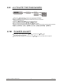
3.10
POWER ON/OFF
TURN OFF When display shows MENU , hold down the EXIT key
for 3 seconds to turn off power.
TURN ON When display is off, hold down the EXIT key for 3 seconds to turn on power.
3 DISPLAY PANEL OPERATION
13
2008.8.13
4
4.1
USING A DMX512 CONTROLLER
BASIC ADDRESSING
Connect all of the units in series using standard DMX512 signal cable or the IP65 rated cable
provided.
Set the DMX512 address in the 'DMX512 Address' menu.
It is possible to have the same DMX address or independent addresses for each fixture.
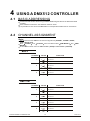
4.2
CHANNEL ASSIGNMENT
Note:
This product has four DMX512 channel configurations (STAGE 1 , STAGE 2 ,PIXEL,
ARC 1 & ARC 1+D).
Both STAGE 1 and STAGE 2 have two DMX modse: DMX MODE 1 and DMX
MODE 2
Ch9 is used to switch from one DMX MODE 1 (0-244) to DMX MODE 2 (245-255).
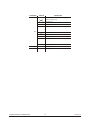
ARC 1
CHANNEL
VALUE
FUNCTION
RED
1
0
4
No function
5
255
0-100%
0
4
No function
5
255
0-100%
0
4
No function
5
255
0-100%
GREEN
2
BLUE
3
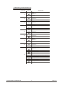
ARC 1+D
CHANNEL
VALUE
FUNCTION
DIMMER
1
0
4
No function
5
255
0-100%
0
4
No function
5
255
0-100%
0
4
No function
5
255
0-100%
RED
2
GREEN
3
BLUE
4
4 USING A DMX512 CONTROLLER
0
4
No function
5
255
0-100%
14
2008.8.13
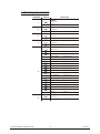
STAGE 1(DMX MODE 1)
CHANNEL
VALUE
FUNCTION
RED
1
0
4
No function
5
255
0-100%
0
4
No function
5
255
0-100%
0
4
No function
5
255
0-100%
0
4
No function
5
255
0-100%
0
4
No function
5
255
0-100%
GREEN
2
BLUE
3
YELLOW
4
CYAN
5
PURPLE
6
0
4
No function
5
255
0-100%
0
4
No function
5
255
0-100%
0
4
No function
5
255
Strobe (slow to fast)
0
4
No function
WHITE
7
STROBE
8
MODE SELECTION
9
4 USING A DMX512 CONTROLLER
5
34
Color-Cycle Mode 1
35
64
Color-Cycle Mode 2
65
94
Color-Cycle Mode 3
95
124
Color-Cycle Mode 4 (speed can be adjusted using Channel 11)
125
154
Color-Cycle Mode 5
155
184
Color-Cycle Mode 6
185
214
Color-Cycle Mode 7
215
244
Color-Cycle Mode 8
245
255
DMX MODE 2
15
2008.8.13
CHANNEL
VALUE
FUNCTION
ID ADDRESS SELECTION (also see pg. 26)
0
9
Select all ID addresses
10
19
ID address #1
20
29
ID address #2
30 . 39
.
.
.
.
.
ID address #3
10
200
209
ID address #20
210
ID address #21
211
ID address #22
212
.
.
.
.
.
.
ID address #23
255
ID address #66
MODULE SELECTION
11
0
4
#1 ON #2 ON #3 ON
5
34
#1 ON
35
64
#2 ON
65
94
#3 ON
95
124
#1 ON #2 ON
125
154
#2 ON #3 ON
155
184
#1 ON #3 ON
185
214
#1 ON #2 ON #3 ON
215
255
#1 OFF #2 OFF #3 OFF
0
255
Speed control of CH9 Color-Cycle Mode 4
EFFECT MACRO
12
0
4
No function
5
9
Effect MACRO #1
14
Effect MACRO #2
.
.
.
.
.
.
255
Effect MACRO #50
10
250
4 USING A DMX512 CONTROLLER
.
.
.
.
.
.
16
2008.8.13
STAGE 1(DMX MODE 2)
CHANNEL
VALUE
FUNCTION
MODULE #1
1
0
4
No function
5
34
RED
35
64
GREEN
65
94
BLUE
95
124
YELLOW
125
154
PURPLE
155
184
CYAN
185
255
PINK-WHITE
MODULE #2
2
0
4
No function
5
34
RED
35
64
GREEN
65
94
BLUE
95
124
YELLOW
125
154
PURPLE
155
184
CYAN
185
214
PINK-WHITE
MODULE #3
3
0
4
No function
5
34
RED
35
64
GREEN
65
94
BLUE
95
124
YELLOW
125
154
PURPLE
155
184
CYAN
185
214
PINK-WHITE
4
NO FUNCTION
5
NO FUNCTION
6
NO FUNCTION
7
NO FUNCTION
STROBE
8
0
4
No function
5
255
Strobe (slow to fast)
MODE SELECTION
9
4 USING A DMX512 CONTROLLER
0
244
DMX MODE 1
245
255
DMX MODE 2
17
2008.8.13
CHANNEL
VALUE
FUNCTION
ID ADDRESS SELECTION (also see pg. 26)
10
4 USING A DMX512 CONTROLLER
0
9
Select all ID addresses
10
19
ID address #1
20
29
ID address #2
30 . 39
.
.
.
.
.
ID address #3
209
200
ID address #20
210
ID address #21
211
ID address #22
212
.
.
.
.
.
.
ID address #23
255
ID address #66
11
NO FUNCTION
12
NO FUNCTION
18
2008.8.13
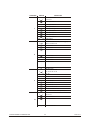
STAGE 2(DMX MODE 1)
CHANNEL
VALUE
FUNCTION
DIMMER
1
0
4
No function
5
255
0-100%
0
4
No function
5
255
0-100%
0
4
No function
5
255
0-100%
0
4
No function
5
255
0-100%
0
9
No function
10
29
RED
(100%)
30
39
RED+GREEN
(R85%+G15%)
40
49
RED+GREEN
(R60%+G40%)
50
69
YELLOW
(100%)
70
79
RED+GREEN
(R15%+G85%)
80
89
RED+GREEN
(R40%+G60%)
90
109
GREEN
(100%)
110
119
GREEN+BLUE
(G85%+B15%)
120
129
GREEN+BLUE
(G60%+B40%)
130
149
BLUE
(100%)
150
159
BLUE+GREEN
(G85%+B15%)
160
169
BLUE+GREEN
(G60%+B40%)
170
189
CYAN
(100%)
190
199
GREEN+PURPLE
(G50%+P50%)
200
219
PURPLE
(100%)
220
229
PURPLE+GREEN
(P80%+G20%)
230
249
RGB
(100%)
250
255
WHITE
(100%)
RED
2
GREEN
3
BLUE
4
COLOR MACROS
5
STROBE
6
4 USING A DMX512 CONTROLLER
0
4
No function
5
255
Strobe (slow to fast)
19
2008.8.13
CHANNEL
VALUE
FUNCTION
MODE SELECTION
7
0
4
No function
5
34
Color-Cycle Mode 1
35
64
Color-Cycle Mode 2
65
94
Color-Cycle Mode 3
95
124
Color-Cycle Mode 4 (speed can be adjusted using Channel 11)
125
154
Color-Cycle Mode 5
155
184
Color-Cycle Mode 6
185
214
Color-Cycle Mode 7
215
244
Color-Cycle Mode 8
245
255
DMX MODE 2
ID ADDRESS SELECTION (also see pg. 26)
0
9
Select all ID addresses
10
19
ID address #1
20
29
ID address #2
30 . 39
.
.
.
.
.
ID address #3
8
209
200
ID address #20
210
ID address #21
211
ID address #22
212
.
.
.
.
.
.
ID address #23
255
ID address #66
MODULE SELECTION
0
9
4
#1 ON #2 ON #3 ON
5
34
#1 ON
35
64
#2 ON
65
94
#3 ON
95
124
#1 ON #2 ON
125
154
#2 ON #3 ON
155
184
#1 ON #3 ON
185
214
#1 ON #2 ON #3 ON
215
255
#1 OFF #2 OFF #3 OFF
0
255
Speed control of Ch7 Color-Cycle Mode 4
EFFECT MACRO
10
0
4
No function
5
9
Effect MACRO #1
14
Effect MACRO #2
.
.
.
.
.
.
255
Effect MACRO #50
10
250
4 USING A DMX512 CONTROLLER
.
.
.
.
.
.
20
2008.8.13
STAGE 2(DMX MODE 2)
CHANNEL
VALUE
FUNCTION
MODULE #1
1
0
4
No function
5
34
RED
35
64
GREEN
65
94
BLUE
95
124
YELLOW
125
154
PURPLE
155
184
CYAN
185
255
PINK-WHITE
MODULE #2
2
0
4
No function
5
34
RED
35
64
GREEN
65
94
BLUE
95
124
YELLOW
125
154
PURPLE
155
184
CYAN
185
214
PINK-WHITE
MODULE #3
3
0
4
No function
5
34
RED
35
64
GREEN
65
94
BLUE
95
124
YELLOW
125
154
PURPLE
155
184
CYAN
185
214
PINK-WHITE
4
NO FUNCTION
5
NO FUNCTION
STROBE
6
0
4
No function
5
255
Strobe (slow to fast)
MODE SELECTION
7
4 USING A DMX512 CONTROLLER
0
244
DMX MODE 1
245
255
DMX MODE 2
21
2008.8.13
CHANNEL
VALUE
FUNCTION
ID ADDRESS SELECTION (also see pg. 26)
8
0
9
Select all ID addresses
10
19
ID address #1
20
29
ID address #2
30 . 39
.
.
.
.
.
ID address #3
209
200
ID address #20
210
ID address #21
211
ID address #22
212
.
.
.
.
.
.
ID address #23
255
ID address #66
9
NO FUNCTION
10
NO FUNCTION
PIXEL
CHANNEL
4 USING A DMX512 CONTROLLER
VALUE
FUNCTION
1~9
1
2
0
4
NO FUNCTION
5
255
BLOCK1-RED
5
255
BLOCK1-GREEN
3
5
255
BLOCK1-BLUE
4
5
255
BLOCK2-RED
5
5
255
BLOCK2-GREEN
6
5
255
BLOCK2-BLUE
7
5
255
BLOCK3-RED
8
5
255
BLOCK3-GREEN
9
5
255
BLOCK3-BLUE
22
2008.8.13
4.3
BASIC INSTRUCTIONS FOR DMX512
OPERATION
STAGE 1 DMX MODE 1
RED, GREEN & BLUE COLOR SELECTION
CH1, CH2 & CH3 control the intensity ratio of each of the RED, GREEN & BLUE LEDs.
When the slider is at the highest position (255) the intensity of the color is the
maximum.
CH1, CH2 & CH3 can be combined together to create over 16 million colors.
CH1, CH2, CH3 have priority over CH4, CH5, CH6 & CH7
YELLOW, CYAN, PURPLE & WHITE
CH4, CH5, CH6 & CH7 are independent colors and cannot be mixed with any other
color control channel.
When multiple channels are used at the same time;lower channel number is priority
(i.e. CH4 has priority over all channels 1-6)
STROBE
CH8 is the strobe channel and controls the strobe effects of CH1, CH2, CH3, Ch4,
CH5, CH6, & CH7
The strobe is with an adjustable speed with a maximum of 20Hz.
The strobe is not active with CH9 & CH12
MODE SELECTION
CH9 allows the user to activate DMX MODE 1 (0-244) or DMX MODE 2 (245-255).
CH9 values 5-244 can only be activated when CH1 to CH7 are not
activated
When Color-Cycle Mode 4 is selected CH11 controls the speed of the Color-cycle.
ID ADDRESS SELECTION
CH10 is used to select the target ID address.
Each independent DMX address may have upto 66 independent ID addresses.
An ID address of 0 will be activated by all ID address locations.
MODULE SELECTION
CH11 controls set combinations of the three LED MODULES present in each unit.
CH11 has priority over CH12 when first activated
EFFECT MACRO
The effect MACRO channel allows the user to select from combinations of different
colors and LED modules in a quick-and-easy action.
CH12 has priority over color control channels (CH1, CH2, CH3, CH4, CH5, CH6 &
CH7)
CH12 has priority over CH11 when first activated
CH12 has priority over Ch9 & Ch11
4 USING A DMX512 CONTROLLER
23
2008.8.13
STAGE 1 DMX MODE 2
MODULE #1, MODULE #2 & MODULE #3 SELECTION
CH1, CH2 & CH3 allow quick-and-simple control of the three LED MODULEs
Control of the LED MODULEs can be used in conjunction with all other channels in
DMX MODE 2
STROBE
CH8 is the strobe channel and controls the strobe effects of CH1, CH2 & Ch3
The strobe is with an adjustable speed with a maximum of 20Hz.
MODE SELECTION
CH9 allows the user to activate DMX MODE 1 (0-244) or DMX MODE 2 (245-255).
ID ADDRESS SELECTION
CH10 is used to select the target ID address.
Each independent DMX address may have up to 66 independent ID addresses.
STAGE 2 DMX MODE 1
DIMMER
CH1 control the dimmer intensity of Ch2, Ch3, Ch4, Ch5, Ch6 & Ch9.
When Ch1is set to 0 , Ch2, Ch3, Ch4, Ch5, Ch6 & Ch9 no funtion..
When the slider is at the highest position (255) the dimmer intensity is the maximum.
CH1 has priority over Ch7 when first activated.
RED, GREEN & BLUE COLOR SELECTION
CH2 , Ch3 & CH4 control the intensity ratio of each of the RED, GREEN & BLUE
LEDs.
When the slider is at the highest position (255) the intensity of the color is the
maximum.
CH2 , Ch3 & CH4 can be combined together to create over 16 million colors.
COLOR MACRO
The COLOR MACRO channel allows the user to select from different color macro .
Ch5 has priority over Ch2, Ch3 & Ch4.
STROBE
CH6 is the strobe channel and controls the strobe effects of CH2, CH3, Ch4, CH5 &
CH9
The strobe is with an adjustable speed with a maximum of 20Hz.
The strobe is not active with CH7 & CH10
MODE SELECTION
CH7 allows the user to activate DMX MODE 1 (0-244) or DMX MODE 2 (245-255).
Ch7 has priority over Ch1 when first activated.
Ch7 has priority over Ch10 when first activated.
When Color-Cycle Mode 4 is selected Ch9 controls the speed of the Color-cycle.
ID ADDRESS SELECTION
CH8 is used to select the target ID address.
Each independent DMX address may have upto 66 independent ID addresses.
An ID address of 0 will be activated by all ID address locations.
MODULE SELECTION
Ch9 controls set combinations of the three LED MODULES present in each unit.
EFFECT MACRO
The effect MACRO channel allows the user to select from combinations of different
colors and LED modules in a quick-and-easy action.
CH10 has priority over CH1.
CH10 has priority over Ch7 when first activated
4 USING A DMX512 CONTROLLER
24
2008.8.13
STAGE 2 DMX MODE 2
MODULE #1, MODULE #2 & MODULE #3 SELECTION
CH1, CH2 & CH3 allow quick-and-simple control of the three LED MODULEs
Control of the LED MODULEs can be used in conjunction with all other channels in
DMX MODE 2
STROBE
CH6 is the strobe channel and controls the strobe effects of CH1, CH2 & Ch3
The strobe is with an adjustable speed with a maximum of 20Hz.
MODE SELECTION
CH7 allows the user to activate DMX MODE 1 (0-244) or DMX MODE 2 (245-255).
ID ADDRESS SELECTION
CH8 is used to select the target ID address.
Each independent DMX address may have up to 66 independent ID addresses.
ARC 1 MODE
RED, GREEN & BLUE COLOR SELECTION
CH1 , Ch2 & CH3 control the intensity ratio of each of the RED, GREEN & BLUE
LEDs.
When the slider is at the highest position (255) the intensity of the color is the
maximum.
CH1 , Ch2 & Ch3 can be combined together to create over 16 million colors.
PIXEL
Every color in each module used as one pixel.
For example, in module #1:
12 red leds = one pixel
12 green leds = one pixel
12 blue leds = one pixel
4 USING A DMX512 CONTROLLER
25
2008.8.13
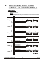
4.4
PROGRAMMING WITH A DMX512
CONTROLLER: EXAMPLES(STAGE 1)
EXAMPLE 1
Before any operation is performed on the DMX512 controller, confirm that all DMX
channels are set to zero.
NOTE
When programming a step / scene that involves operating CH10 to select an ID address,
this channels operation should be performed first
Step 1
Step 2
Step 3
Step 4
Step 5
Step 6
CH1
20
to select RED for MODULE #1 (ID Add. 1)
CH2
0
to select OFF for MODULE #2 (ID Add. 1)
CH3
0
to select OFF for MODULE #3 (ID Add. 1)
CH9
255
11
to select ID Add. 1
CH1
0
to select OFF for MODULE #1
CH2
20
to select RED for MODULE #2 (ID Add. 1)
CH3
0
to select OFF for MODULE #3 (ID Add. 1)
CH9
255
11
to select ID Add: 1
CH1
0
to select OFF for MODULE #1 (ID Add. 1)
CH2
0
to select OFF for MODULE #2
CH3
20
CH9
255
50
CH2
0
to select GREEN for MODULE #1
(ID Add. 1 & ID Add. 2)
to select OFF for MODULE #2
(ID Add. 1 & ID Add. 2)
CH3
0
to select OFF for MODULE #3
CH9
255
50
CH3
0
CH9
255
CH10
0
CH1
0
CH2
0
CH3
50
CH9
255
CH10
0
ID Addr.2
ID Addr.1
ID Addr.2
ID Addr.1
ID Addr.2
ID Addr.1
ID Addr.2
to select ID Add: 1
CH1
CH2
ID Addr.1
to select DMX mode 2
11
0
ID Addr.2
to select RED for MODULE #3 (ID Add. 1)
CH10
CH1
ID Addr.1
to select DMX mode 2
CH10
0
ID Addr.2
to select DMX mode 2
CH10
CH10
ID Addr.1
to select DMX mode 2
to select all ID Addresses
to select OFF for MODULE #1
(ID Add. 1 & ID Add. 2)
to select GREEN for MODULE #2
(ID Add. 1 & ID Add. 2)
to select OFF for MODULE #3
(ID Add. 1 & ID Add. 2)
to select DMX mode 2
to select all ID Addresses
to select OFF for MODULE #1
(ID Add. 1 & ID Add. 2)
to select OFF for MODULE #2
(ID Add. 1 & ID Add. 2)
to select GREEN for MODULE #3
(ID Add. 1 & ID Add.2)
to select DMX mode 2
Red
to select all ID Addresses
4 USING A DMX512 CONTROLLER
26
Green
Blue
2008.8.13
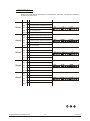
EXAMPLE 2
Before any operation is performed on the DMX512 controller, confirm that all DMX
channels are set to zero.
Step 1
Step 2
Step 3
255
CH2
0
CH3
0
to select NO GREEN for all MODULES
(ID Add.1)
to select NO BLUE for all MODULES
(ID Add.1)
CH9
0
to select DMX mode 1
CH10
11
to select ID Add. 1
CH1
0
to select OFF for all MODULES (ID Add. 1)
CH2
0
CH3
0
to select NO GREEN for all MODULES
(ID Add.1)
to select NO BLUE for all MODULES
(ID Add.1)
CH9
0
to select DMX mode 1
CH10
11
to select ID Add: 1
CH1
0
CH2
0
CH3
255
CH9
0
CH20
Step 4
Step 6
12
to select NO RED for all MODULES
(ID Add.2)
to select NO GREEN for all MODULES
(ID Add.2)
CH2
50
CH3
0
CH9
0
to select DMX mode 2
ID Addr.2
ID Addr.1
ID Addr.2
ID Addr.1
ID Addr.2
ID Addr.1
ID Addr.2
ID Addr.1
ID Addr.2
to select all ID Addresses
CH1
0
to select OFF for MODULE #1 (ID Add. 2)
CH2
0
to select GREEN for MODULE #2 (ID Add. 2)
CH3
0
to select OFF for MODULE #3 (ID Add.1)
CH9
0
to select DMX mode 2
CH10
0
to select ID Add: 2
CH1
20
to select RED for MODULE #1 (ID Add. 2)
CH2
50
to select GREEN for MODULE #2 (ID Add. 2)
CH3
80
to select BLUE for MODULE #3 (ID Add. 2)
CH9
0
12
ID Addr.1
to select ID Add: 2
to select NO GREEN for all MODULES
(ID Add.1 & ID Add.2)
to select GREEN for all MODULES
(ID Add.1 & ID Add.2)
to select NO GREEN for all MODULES
(ID Add.1 & ID Add. 2)
CH10
ID Addr.2
to select DMX mode 1
0
20
ID Addr.1
to select BLUE for all MODULES (ID Add. 2)
CH1
CH10
Step 5
to select RED for all MODULES (ID Add. 1)
CH1
to select DMX mode 2
to select ID Add: 2
Red
4 USING A DMX512 CONTROLLER
27
Green
Blue
2008.8.13
Step 7
Step 8
CH1
0
to set OFF for MODULE #1 (ID Add. 1)
CH2
0
to select OFF for MODULE 2 (ID Add.1)
CH3
0
to select OFF for MODULE 3 (ID Add.1)
CH9
0
to select DMX mode 1
CH10
11
to select ID Add. 1
CH1
255
CH2
0
CH3
0
to select NO GREEN for all MODULES
(ID Add.2)
to select NO BLUE for all MODULES
(ID Add.2)
CH9
0
to select DMX MODE 1
CH10
12
ID Addr.1
ID Addr.2
ID Addr.1
ID Addr.2
to select RED for all MODULES (ID Add. 2)
to select ID Add: 2
Red
4 USING A DMX512 CONTROLLER
28
Green
Blue
2008.8.13
EXAMPLE 3
Before any operation is performed on the DMX512 controller, confirm that all DMX
channels are set to zero.
Step 1
Step 2
CH1
255
to select RED for all MODULES (ID Add. 1)
CH2
0
to select NO GREEN for all MODULES (ID Add. 1)
CH3
0
to select NO BLUE for all MODULES (ID Add.1)
CH9
0
to select DMX mode 1
CH10
11
to select ID Add. 1
CH1
0
to select NO RED for all MODULES (ID Add.2)
CH2
255
to select GREEN for all MODULES (ID Add.2)
CH3
0
to select NO BLUE for all MODULES (ID Add. 2)
CH9
0
to select DMX mode 1
CH10
Step 3
Step 5
to select ID Add: 2
CH1
0
to select NO RED for all MODULES (ID Add.3)
CH2
0
to select NO GREEN for all MODULES (ID Add.3)
CH3
255
CH9
0
CH10
Step 4
12
13
to select BLUE for all MODULES (ID Add.3)
to select DMX mode 1
to select ID Add: 3
CH1
0
to select NO RED for all MODULES (ID Add.1)
CH2
0
to select NO GREEN for all MODULES (ID Add.1)
CH3
0
to select NO BLUE for all MODULES (ID Add.1)
CH9
0
to select DMX mode 1
CH10
11
to select ID Add. 1
CH1
0
to select NO RED for all MODULES (ID Add.2)
CH2
0
to select NO GREEN for all MODULES (ID Add.2)
CH3
0
to select NO BLUE for all MODULES (ID Add.2)
CH9
0
to select DMX mode 1
CH10
12
to select ID Add: 2
Red
4 USING A DMX512 CONTROLLER
29
Green
Blue
2008.8.13
5
APPENDIX
5.1
TROUBLE SHOOTING
LED MODULE
SITUATION
CAUSE
ACTION
PART ORDER NUMBER
1) Power connection error
1) Check all power connections
2) Main PCB fuse overheated
2) Replace fuse
16-03-0020-03
3) Main PCB damaged
3) Replace main PCB
26-2A-LED301MD4-00
LED MODULE on,
Display board damaged
but no control
from display
Replace display board
26-2A-LED301DI-01
LEDs of the same
LED PCB damaged
color are not lit
Replace PCB board
26-2A-LED301Light-00
LEDs of all colors Main PCB damaged
are not lit
Replace main PCB
26-2A-LED301MD4-00
No display
Display normal,
but no respon
se to DMX512
controller
1) Signal connection error
1) Check all signal connections
2) DMX address error
2) Check DMX address setting
Version 4.0
5 APPENDIX
30
2008.8.13